Abstract
The FEM (finite element method), FEM-SPH (smoothed particle hydrodynamics method) adaptive coupling method and the coupled Eulerian-Lagrangian method (CEL) are introduced to simulate the engraving process. Eight-node hexahedral elements were mainly used to build the finite element models of the rotating band engraving into the gun barrel except in CEL simulation. In this case, the rotating band model and mesh are both built in ABAQUS in order to meet the requirements of CEL simulation. The simulation results include the deformation process of the rotating band, the motions of the projectile, the dynamic engraving resistance and the calculating efficiency were obtained, compared and analyzed. The advantages and disadvantages of numerical methods when simulating engraving process are discussed. The results show that the FEM-SPH adaptive coupling method and the CEL method have advantages for applications involving the simulation of the engraving process. The intent is to better understand the numerical methods and eventually broaden the utilizations in analyses of interior ballistics.
1. Introduction
Ballistics is generally divided into three phases: interior, intermediate and exterior ballistics. In general, internal phase is the process from the propellant’s ignition to the projectile leaves the gun muzzle. This study is essential for designing guns, from small-bore guns to high-tech one. Engraving process is the beginning of the interior ballistics, which always features as transient experience, high temperature, intensive impact, high-speed friction and large deformation. Therefore, it determines the initial conditions of interior ballistics. Classical interior ballistics based on the traditional instantaneity assumption ignores the transient engraving process and the relationship between the chamber pressure and the projectile motions. Due to the limitations of numerical approaches, Qierbarov E. B. [1], Zhou Y. H. et al. [2] and Zhang X. F. et al. [3] conducted their studies with just taking into account the elastic behavior of the rotating band. However, with the development of the scientific research approaches and the modern guns with characteristics of high muzzle velocity and high firing accuracy promote further investigations of the rotating band engraving process.
The major function of a gun is to accurately fire projectiles towards a target at high velocity. As a significant part of interior ballistics, the different prospects of the engraving process have been studied through a lot of methods.
Keinänen H. et al. [4] discussed how the material properties of the rotating band impacts the engraving process through numerical and testing approaches respectively. But in the numerical studies, more accurate material constitutive model should be introduced. Wu et al. [5] was working on the interaction behaviors during the engraving process. They used copper and nylon as the rotating band material, conducting the tests under the quasi-static and dynamic loading conditions. Their studies were based on an electronic universal testing machine. And they also designed a gas-gun-based test rig to perform their studies. They concluded that the strain rate has significant effects on the deformation behaviors of rotating bands. Carlucci et al. [6] use projectile-borne sensors to measure base pressure and acceleration of projectiles during the engraving process. But in that study, an inevitable problem is how to calibrate the accelerometer accurately under such a high level of acceleration. Besides, the inertial property of the projectile does not always stay the same in the whole procedure. It will change the kinematics of projectiles during the engraving process.
Tao C. et al. [7] studied the influences of the engraving process on the interior ballistic peak phenomenon, and some kinds of limitations were unavoidable due to the adoption of traditional formula for engraving pressure and engraving resistance. The research worked in the influences of different bore structures on engraving process reported by Sun H. Y. [8] and the study on influences of bore structures on gun’s interior ballistic performances [9] were both carried out by utilizing explicit finite element methods and had obtained valuable results, though the issues of dynamic engraving resistance and engraving pressure should have been paid more attention. But the finite element method is not perfect while simulating the issue of the engraving process [8-9], because Lagrangian finite elements will be highly distorted and lose accuracy during this process. Then, the explicit dynamic algorithm and Arbitrary Lagrangian-Eulerian (ALE) adaptive meshing technology is used to numerically simulate the entering process of lead core projectile [10]. For the guns with the feature of high muzzle velocities, however, ALE adaptive meshing technology is inadaptable to such high-speed deformation. In order to overcome the weakness of traditional FEM while involving in large deformation, SPH was introduced. The SPH method does not need any grid when calculating the space derivative, which can address large deformation problems effectively. Ma M. D. et al. [11] established a projectile-barrel coupled system based on the coupling algorithm of FEM and SPH. They intensively studied the plastic flow and the stress/strain varying laws of the bearing band. However, the SPH method is not a perfect numerical tool to resolve this problem either. Firstly, if the nodes are not placed in a regular cubic arrangement, the mass distribution is somewhat inexact. Unfortunately, the rotating band usually does not have a uniform shape. As a result, the attributes of the band using the SPH are not as accurate as the rotating band using the FEM. In this case, the kinematics of the projectile will be changed. Secondly, the total simulation time is generally long.
Through the introduction above, numerical simulation is an advanced way to study the transient dynamic characteristics of the engraving process. But more effective and more efficient approaches should be introduced in the study. The goal of present research is to better utilize the numerical algorithms to investigate and analyze the engraving process. This paper will investigate a new method based on the studies of Ma M. D. [11]. And then, a method which is called CEL will be adapted for the study.
2. Rotating band engraving process
2.1. Geometry of gun barrel and projectile
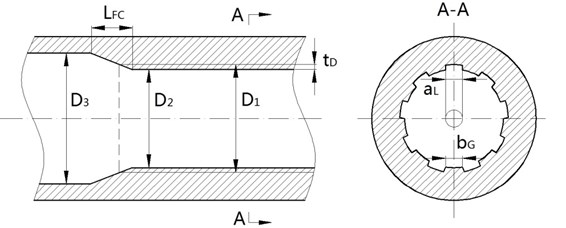
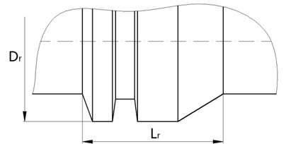
The schematic diagram of the rifled barrel is shown in Fig. 1(a). D3 is the chamber diameter and LFc is forcing cone length. The cross-sectional view of the rifling is shown in A-A of Fig. 1(a). The lands are considered as trapezoid and the grooves are considered as rectangle. The number of lands in the studies is 36, the main parameters include the width of the land aL, the width of the groove bG, the depth of the groove tD, the land diameter D2 and the groove diameter D1. The structure of the rotating band is shown in Fig. 1(b). The main parameters are the diameter of the rotating band Dr and the length of the rotating band Lr.
2.2. Engraving process
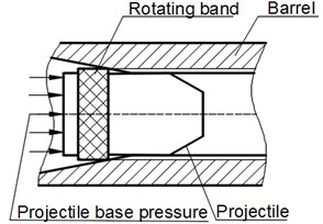
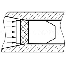
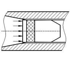
The engraving process is shown in Fig. 2. At the beginning, the projectile is loaded to its designated position, in Fig. 2(a). When the firing starts, as propellant gas pressure in the chamber rises, the projectile starts to move. As propellant gas pressure increases, the rotating band is subjected to plastic deformation and is engraved partly into the rifling, in Fig. 2(b). It indicates the end of the engraving process when the rotating band is completely engraved into the rifling, in Fig. 2(c).
Fig. 1a) The structures of rifled barrel and b) rotating band
a)
b)
Fig. 2Rotating band engraving process
a)
b)
c)
2.3. Basic assumptions
According to the main features of the engraving process, some assumptions are made to simplify the numerical calculation [12]:
1) There do not have initial stress and deformation on the rotating band when it is loaded into its designated position.
2) The aerodynamic force in front of the projectile, the dynamic unbalance and the gravity of the projectile are neglected. The recoil of the gun tube is neglected.
3) The influences of the thermal field are ignored.
3. Material model
The elastic model is utilized to perform the material behavior of the rifled barrel and the projectile body, they are both made of steel, the main parameters are ρ=7850 kg/m3, E=207 GPa, and ν=0.29. The rotating band is made of CuZn10 brass. During the engraving process, the rotating band is subjected to large plastic deformation and material failure. Its material properties are represented by material constitutive model.
3.1. Plastic model of rotating band
The Johnson-Cook plastic model [13] is used to describe the plastic behavior of the rotating band, its expression is Eq. (1):
where εp and ˙εp are the effective plastic strain and the effective plastic strain rate respectively, ˙ε0 is the reference strain rate, T, Tr, Tm are respectively the actual temperature, room temperature and the melting temperature in the absolute scale, and A, B, C, m, n are material constants.
3.2. Failure criteria of rotating band
The Johnson-Cook failure model [14] is used to perform the material failure of the rotating band. The effective failure strain is used to determine the damage parameters. The expression is shown by Eq. (2):
where d1,…,d5 are the constants of material failure, σ* is the stress triaxiality defined by σ*=σH/σeq in which σH is the hydrostatic stress and σeq is the equivalent von Mises stress.
The damage accumulation is expressed by Eq. (3):
where D is the damage parameter to material elements. Failure happens once D=1, and in the FEM simulations element erosion is used to remove elements that have reached the critical damage. The Johnson-Cook plastic and failure constitutive model parameters for CuZn10 brass are shown in Table 1.
Table 1Material parameters for CuZn10 brass
Quantities | Constants | Quantities | Constants | Quantities | Constants |
ρ / (Kg/m3) | 8944 | C | 0.025 | d1 | 0.54 |
E / (MPa) | 121000 | n | 0.31 | d2 | 4.89 |
v | 0.33 | m | 1.09 | d3 | 3.031 |
A / (MPa) | 90 | MT / (K) | 1355 | d4 | 0.014 |
B/ (MPa) | 292 | TT/ (K) | 293 | d5 | 1.12 |
4. Dynamic finite element modeling and calculation
4.1. Element mesh
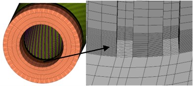
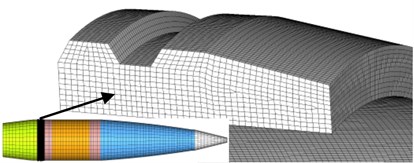
Eight node hexahedral elements are used to build finite element model which has been shown in Fig. 3 is meshed by the HyperMesh software. Numerical simulations are performed by ABAQUS. The rotating band and the front of the rifling are composed of deformable elements with a finer mesh. The width of the band is 22 mm. There is a total of 582,830 elements, and the rotating band has 479,412 elements. This model will be used during the studies of the engraving process except CEL analysis. In CEL analysis, as a Eulerian section, the rotating band must be built in ABAQUS [15].
Fig. 3Mesh of finite element model
4.2. Contact between the rotating band and the tube
The contact between the rotating band and the inner wall of the tube is modeled using a *GENERIAL CONTACT algorithm available in ABAQUS. The implementation of Eulerian-Lagrangian contact is an extension of general contact in Abaqus/Explicit. The finite element models are solved by the explicit integration algorithm. For purpose of promoting the increase stability and efficiency of the calculation, the single point integration and the stiffness hourglass control methods were introduced.
4.3. Loads and boundary conditions
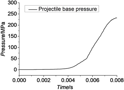
As is known to all, the projectile is pushed by pressure of combustion gas during live firing. This pressure is the main driving power during internal phase. The projectile base pressure is given by Fig. 4. It was obtained by live firing. Projectile base pressure is loaded as *PRESSURE on the base of the projectile in ABAQUS.
According to the assumptions presented in Section 2.3, the front end face of the barrel is fixed.
Fig. 4Projectile base pressure
5. Numerical algorithms
5.1. FEM-SPH adaptive coupling method
The SPH method was first proposed by L. B. Lucy [16]. Since then, the computational cost has still been a significant problem. The FEM-SPH adaptive coupling method [17] can take advantage of the intrinsic strengths of both Lagrangian finite element and SPH methods when modeling a body. We can define the model with Lagrangian finite elements and convert them to SPH particles either at the beginning of an analysis or after the deformation becomes significant. The conversion functionality is intended to be used when the deformations in the original finite element mesh are significant and elements may distort. Traditionally, in such cases deletion of the soon-to-be distorted Lagrangian elements would be the only choice to allow analyses to continue. Converting to SPH particles provides an improvement over the element deletion option because the generated particles are able to provide resistance to deformation beyond finite element distortion levels. Therefore, it can address the elements distortion on one hand, and improve the computational efficiency on the other hand [15].
In order to automatically transform the element to the particle, an effective criterion is needed to determine the degree of distortion of the elements. In the study of high-speed impact, the distortion degree can be judged based on the physical criterion or the geometric criterion. Some scholars have tried to use the equivalent plastic strain [17], maximum principal stress [18] or other physical quantities to determine the elements which have to be converted to particles.
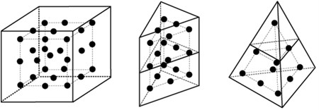
In ABAQUS, when using the conversion technique, particles are generated internally at the beginning of the preprocessing phase of an analysis, and they are placed in an inactive or dormant state. The particles are attached to the parent elements in a similar fashion as the nodes of embedded elements are attached, as shown in Fig. 5, and they follow the motion of the parent element nodes in an average sense. Upon conversion the state information (such as stress or equivalent plastic strain) associated with the element being converted is transferred to the generated particles [15].
In this paper, the rotating band will be set as the convertible region. Other parts of the engraving system will still utilize Lagrangian finite elements. The law of conversion is Mises Stress.
Fig. 5Internally generated particles per parent element
5.2. CEL method
In the traditional Lagrangian analyses, nodes are fixed within the material, and elements deformation equal to material deformation. Lagrangian element is always 100 % full of material, so the material boundary and elements boundary are the same. In the Eulerian analysis is just the opposite. In this case, nodes are fixed in space. Material can flow through elements and do not deform [19, 20]. The Eulerian time incrementation algorithm which is known as ‘Lagrange-plus-remap’ is based on an operator split of the governing equations, leading to a traditional Lagrangian phase followed by a Eulerian phase. As we have mentioned above, during the Lagrangian phase of the time increments nodes are assumed to be fixed within the material temporarily. But during the Eulerian phase of the time increments, deformation being suspended, elements with extreme deformation are automatically remeshed, and the corresponding material flows between the elements are computed. The different features of Lagrangian description and Eulerian description have been shown by Fig. 6 [21].
The CEL method was first proposed by Noh in 1964 [22]. It picks up the strengths of both Lagrangian and Eulerian method. In ABAQUS, material is determined by calculating its Eulerian Volume Fraction (EVF) in every element. By definition, the EVF is 1 if an element is completely filled, and vice versa. As it has shown in Fig. 7, the dark grey region on the left is filled with material, and EVFs in this region are all larger than zero. In the case of this paper, in order to get a relatively accurate boundary at the beginning of the analysis, the Eulerian model will be cut deliberately, more details are given by Fig. 8. The top right part of Fig. 8 which will be filled with material is the true shape of the rotating band.
Fig. 6Feature of Lagrangian algorithm and Eulerian algorithm
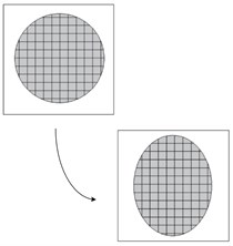
a) Lagrangian description
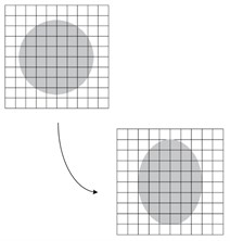
b) Eulerian description
Fig. 7Eulerian volume fraction
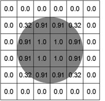
Fig. 8The rotating band of Eulerian analysis
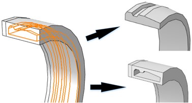
Eulerian-Lagrangian formulation is based on the enhanced contact immersed boundary method. In this method, the Lagrangian mesh occupies void area of the Eularian gird. In ABAQUS, the contact algorithm automatically calculates and tracks the interfaces among Eulerian materials and Lagrangian structure [23].
The CEL method applies explicit dynamic method which is based on the central difference criterion to solve the nonlinear differential equations:
where un, ˙un, ¨unindicate displacement, velocity, and acceleration of nth freedom respectively. ∆t is the time increment. i is the moment of ith increment.
6. Results and analysis
In this section, we analyze the numerical results to compare and discuss advantages and disadvantages of the three different algorithms in this study.
6.1. Deformation process
6.1.1. FEM-based results
Given that the FEM has been widely utilized in engraving simulation. In this study, the FEM-based simulation is used to verify the results of the proposed methods. Fig. 9 is the evolution of von Mises stress of rotation band using FE method.
Because the Lagrangian finite element mesh may cause simulation termination in the case of large deformation, the plastic strain accumulation criterion presented in Section 3.2 was introduced to delete the failed elements. Elements forced to be deleted are shown in Fig. 10. Totally 1232 elements, 0.257 % of the total elements of the rotating band, have been forced to be deleted due to the extreme distortion. These deleted elements’ interior attributes are also deleted. Therefore, it inevitably caused energy loss. Although the energy loss is low, we cannot conclude that the energy will not affect the kinematics of the projectile. From Fig. 10, it can be seen that the failure of the rotating band element occurs more often near the rear of the band. It shows the fact that the material of the rotating band is forced to flow to the rear at first, then, the element failure occurs as the rotating band keeps moving forward.
Fig. 9Evolution of von Mises stress for rotation band under FE method
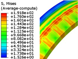
a) 5ms
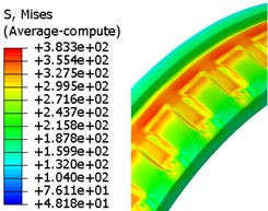
b) 6ms
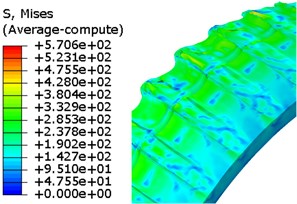
c) 6.85ms
Fig. 10The deleted elements
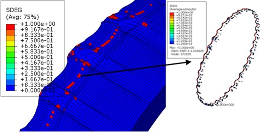
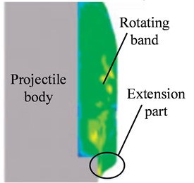
Fig. 11The sectional engraved rotating band
6.1.2. FEM-SPH adaptive coupling method based results
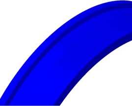
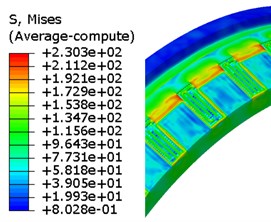
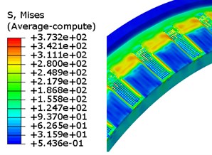
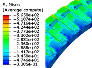
The von Mises stress of engraving simulation using FEM-SPH adaptive coupling method has been given by Fig. 12. At 6.75 ms, the rotating band is engraved into the rifling completely. In order to improve the time efficiency, the converted threshold is set to 200 MPa. In Fig. 12, as we can see, around 5.5 ms, some elements have already been converted to particles. At the end of the engraving process, all elements in the extremely deformed regions have been converted into particles. But it does not have extension part as obvious as Fig. 11 does at the rear of the rotating band. According to the studies [5, 24], it can be explained that the particles start to come off while the rotating band is being engraved. So, using this method cannot properly perform the deformation due to loss of particles.
Using computer with 8 CPUs, the total time of this simulation is 51 hours, and compare with the simulation counted on SPH method for 117 hours, the efficiency is doubled. According to the studies of Sun Z. H. [24], the threshold of conversion usually has uncertain effects on the results, so investigating the effects of the threshold value may be the next target.
6.1.3. CEL-based results
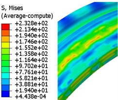
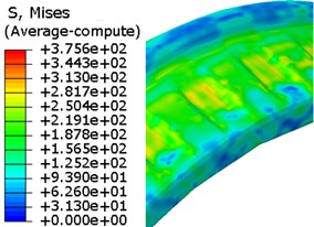
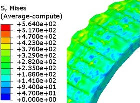
As mentioned in Section 2.2, the Eulerian part must be built in ABAQUS, and the model is given by Fig.8. In this case, there is a total of 695,674 elements in the finite element model, and 592,256 elements among it belong to Eulerian part. But the time cost of this simulation was just 23.5 hours. Fig. 13 shows the evolution of the rotating band during the engraving process simulated by using the CEL method. The engraving process finished in about 6.73 ms.
Fig. 12Evolution of von Mises stress for rotation band under FEM-SPH method
a) 0 ms
b) 5.5 ms
c) 6 ms
d) 6.75 ms
Through observation, the deformation and flow of the material are obtained. The detail of the engraving process is, when the projectile has been loaded, the rotating band kept in contact with the inner wall of the tube closely. Once the projectile base pressure increases to a certain value, the projectile starts to move forward. The diameter of forcing cone is decreasing as the projectile going forward. The front end of the rotating band starts to deform. The elastic and plastic deformation begins to happen, and the original groove of the rotating band starts to be filled as the material is being pushed backward. Then, as the engraving process keeps ongoing, the regions of rotating band where corresponding with rifling lands are forced to be extruded and sheared. Finally, the rotating band is engraved by the rifling lands. The rotating band and the interior wall of the tube are fitted closely. The engraving process ends.
Fig. 13Evolution of von Mises stress for rotation band under CEL method
a) 5 ms
b) 6 ms
c) 6.73 ms
6.1.4. Comparison of groove sizes
Fig. 14 shows a recovered projectile from a live firing. The data of the groove sizes are presented in Table 2. According to the studies of Sun Q. Z. [25], the rotating band is further worn after the engraving process ends. The comparisons in the table also demonstrate this phenomenon: these three results are close or within the range of the experimental data, but they are all close to the lowest value of the experimental data.
Fig. 14Engraved rotating band of a recovered projectile
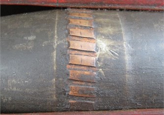
Table 2Comparison of groove sizes
FEM (mm) | CEL (mm) | FEM-SPH (mm) | Experimental data (mm) | |
Depth | 1.44 | 1.44 | 1.43 | 1.41-1.53 |
Width | 2.72 | 2.69 | 2.71 | 2.68-2.81 |
6.2. Projectile motion
The displacement-time curves, velocity-time curves and acceleration-time curves of the projectile are given by Figs. 15-17. We can find that, although the numerical algorithms vary, the trends of the displacement, velocity and acceleration curves of these three simulations are basically the same.
Fig. 15, 16 show the displacement-time curves and the velocity-time curves of the mass center of the projectile respectively. A similarity in trends can be observed from the motion curves. But because of the differences of the numerical methods, the curves are a little bit different, especially the curves obtained from the simulation using FEM. It can be explained by the introduction of the damage accumulation criterion. A research [26] shows that the velocity of the projectile has reached 10 % of the muzzle velocity when the band engraved in rifling completely. The instantaneous velocities of projectile when engraving process finishes versus muzzle velocity are shown in Table 3 respectively.
Fig. 17 shows the acceleration-time curves of the mass center of the projectile. As can be seen, the curves show a similar trend. However, the curves are not as smooth as the displacement and velocity curves. This phenomenon demonstrates that there always have some oscillations during the engraving process.
Fig. 15Displacement-time curves
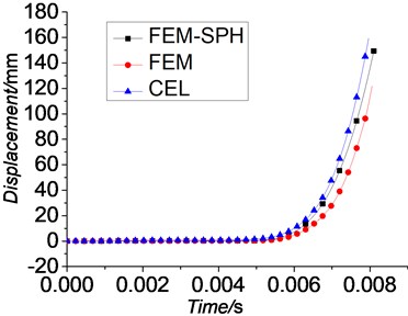
Fig. 16Velocity-time curves
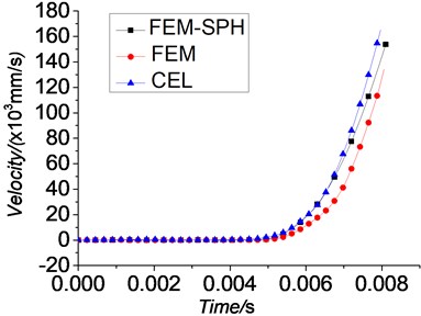
Fig. 17Acceleration-time curves
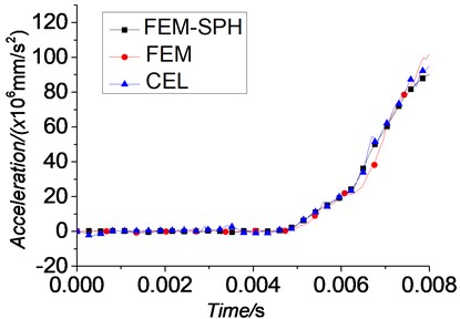
Fig. 18Engraving resistance
6.3. Dynamic engraving resistance
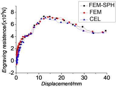
The engraving resistance-displacement curves which are shown in Fig. 18 are similar to those obtained by Wu B. [5]. Through these curves, the oscillations during the engraving process can also be reflected. The law of the dynamic engraving resistance is obtained. When the projectile starts to move, the dynamic engraving resistance rises. As the plastic deformation of the rotating band occurs, the dynamic engraving resistance increases dramatically. When the rotating band starts to contact with the lands, slight waves occur. Then, the dynamic engraving resistance continues increasing significantly until it reaches its peak value. After that, the dynamic engraving resistance almost stays the same until the deformation of the rotating band reduces. After the rotating band engraved into the barrel completely, the engraving resistance maintains almost a constant value. Table 3 shows the peak values of the engraving resistance.
Table 3Comparison of the results
FEM | CEL | FEM-SPH | Ref. [26] | |
Time at engraving completion point (ms) | 6.85 | 6.73 | 6.75 | – |
Calculation cost (h) | 77 | 23.5 | 51 | – |
Displacement at the maximum engraving resistance point (mm) | 14.39 | 14.17 | 14.25 | – |
Maximum engraving resistance value (N) | 7.27×10⁵ | 7.22×10⁵ | 7.23×10⁵ | – |
Engraving pressure at engraving completion point/Maximum pressure (%) | 69.43 | 65.64 | 66.09 | 65 |
Velocity at engraving completion point/Muzzle velocity (%) | 7.90 | 10.28 | 10.20 | 10 |
Jin Z. M. [26] also presented the conclusion that when the engraving process ends, the engraving pressure has reached 173 MPa which is 65 % of the maximum value. Results of engraving pressure through numerical analysis are also shown in Table 3. These conclusions can somehow demonstrate the validity of simulations in this paper.
Table 3 shows the main comparisons in the study. From the data listed in the table, we can find that the new methods can both satisfy the requirements of the accuracy and improve the efficiency.
7. Conclusions
The FEM-SPH adaptive coupling method and the CEL method have been introduced for conducting analyses of the engraving process in this paper. The laws of projectile motion and dynamic engraving resistance etc. during engraving process are studied under these methods. The conclusions are as follows:
1) The FE-SPH adaptive coupling method is first introduced in the simulation of the engraving process. The results show that it can perform well for applications involving extreme deformation. And its efficiency is doubled than the simulation using SPH method, but the computational cost of the analysis increases significantly after the conversion takes place since a larger number of active elements need to be processed. Furthermore, the rotating band did not deform as accurately as the one using FEM. And the effects of the threshold value still need further investigation.
2) The CEL method is first applied on the studies of engraving process too. It can also perform well under extreme deformation. The computational efficiency of this method is improved remarkably. It also addresses the loss of energy that would otherwise be impossible to handle with the FEM. Additionally, the computational accuracy is good. Despite being in the early stages of validation and verification, the CEL approach for further interior ballistics analysis shows great promise in its ability to provide valuable insight.
This paper provides different approaches to investigate rotating band engraving process. Through comparison and analysis, the advantages and disadvantages of these methods in interior ballistics study have been discovered. The intent is to continue pushing the capabilities of numerical simulation so that they may be used more broadly in analyses of interior ballistics.
References
-
Qierbarov E. B. Interior Ballistics and Engraving Force Calculation during Engraving of Projectile. National Defense Industry Press, Beijing, 1997.
-
Zhou Y. H., Wang S. C., et al. Practical Two-Phase Flow Interior Ballistics. The Publishing House of Ordnance Industry, Beijing, 1990.
-
Zhang X. F., Lu X. H., et al. Interior Ballistics of Erosion Guns. National Defense Industry Press, Beijing, 2001.
-
Keinänen H., Moilanen S., Toivola J., et al. Influence of rotating band construction on gun tube loading – part 1: numerical approach. Journal of Pressure Vessel Technology, Vol. 134, Issue 4, 2012, p. 041006.
-
Wu B., Zheng J., et al. Tribology of rotating band and gun barrel during engraving process under quasi-static and dynamic loading. Friction, Vol. 2, Issue 4, 2014, p. 330-342.
-
Carlucci D., Vega J., Pocock M., et al. Novel examination of gun bore resistance analysis and experimental validation. Proceeding of the 23rd International Symposium on Ballistics, Tarragona, Spain, 2007, p. 313-320.
-
Tao C., Zhang Y., Li S., et al. Mechanism of interior ballistic peak phenomenon of guns and its effects. Journal of Applied Mechanics, Vol. 77, Issue 5, 2010, p. 051405.
-
Sun H. Y., Ma J. S., Li W., et al. Influence of different bore structures on engraving process on projectile. Journal of Vibration and Shock, Vol. 30, Issue 3, 2011, p. 30-33.
-
Sun H. Y., Ma J. S., Li W., et al. Study on influence of bore structure on gun’s interior ballistic performances. Acta Armamentarii, Vol. 33, Issue 6, 2012, p. 669-675.
-
Fan L. X., He X. Y., et al. Finite element simulation and process analysis of projectile entering into barrel. Acta Armamentarii, Vol. 32, Issue 8, 2011, p. 963-969.
-
Ma M. D., Cui W. S., Zeng Z. Y., et al. Engraving process analysis of projectiles based on coupling of FEM and SPH. Journal of Vibration and Shock, Vol. 34, Issue 6, 2015, p. 146-150.
-
Sun Q. Z., Yang G. L., Ge J. L., et al. Numerical research on rotating band engraving process of a large-caliber howitzer. Acta Armamentarii, Vol. 36, Issue 2, 2015, p. 207-213.
-
Johnson G. R., Cook W. H. A constitutive model and data for metals subjected to large strains, high strain rates and high temperatures. Proceedings of the 7th International Symposium on Ballistics, Vol. 21, 1983, p. 541-547.
-
Johnson G. R., Cook W. H. Fracture characteristics of three metals subjected to various strains, strain rates, temperatures and pressures. Engineering Fracture Mechanics, Vol. 21, Issue 1, 1985, p. 31-48.
-
ABAQUS 6.14 Analysis User’s Manual. Dassault Systems Inc., Waltham, USA, 2014.
-
Lucy L. B. A numerical approach to the testing of fission hypothesis. The Astronomical Journal, Vol. 82, Issue 12, 1977, p. 1013-1024.
-
Johnson J., Stryk R., Stephen R., et al. An algorithm to automatically convert distorted finite elements into meshless particles during dynamic deformation. International Journal of Impact Engineering, Vol. 27, Issue 10, 2002, p. 997-1013.
-
Zhang Z. C., Qiang H. F., Gao W. R., et al. Conversion of 3d distorted finite elements into SPH particles during impact dynamic deformation. Journal of Xi’an Jiaotong University, Vol. 45, Issue 1, 2011, p. 105-110.
-
Bemson David J. Computational Methods in Lagrangian and Eulerian Hydrocodes. University of California, San Diego, USA, 1990.
-
Benson D. J. Computational methods in Lagrangian and Eulerian hydrocodes. Computer Methods in Applied Mechanics and Engineering, Vol. 99, 1992, p. 235-394.
-
Qiu G., Henke S., Grabe J., et al. Application of a coupled Eulerian-Lagrangian approach on geomechanical problems involving large deformations. Computers and Geotechnics, Vol. 38, 2011, p. 30-39.
-
Noh W. F. CEL. A Time-Dependent Two-Space-Dimensional Coupled Eulerian-Lagrangian Code. Methods in Computational Physics, 1964, p. 117-179.
-
Benson D. J. Contact in a multi-material Eulerian finite element formulation. Computer Methods in Applied Mechanics and Engineering, Vol. 193, 2004, p. 4277-4298.
-
Sun Z. H. Dynamics Response Analysis of Penetration Based on FE-SPH Adaptive Coupling Method. Thesis of Hunan University, Changsha, 2012, p. 1-64.
-
Sun Q.Z. Modeling and simulation on engraving process of projectile rotating band under different charge cases. Journal of Vibration and Control, 2015.
-
Jin Z. M. Interior Ballistics of Guns. Beijing Institute of Technology Press, Beijing, 2004.
Cited by
About this article
The authors would like to acknowledge the financial supports from the Fundamental Research Funds for the Central Universities (No. 30915118825), the National Natural Science Foundation of China (No. 11172139 and No. 11572158) and the Major National Scientific Instrument and Equipment Development Project of China (No. 2013YQ47076508).

