Abstract
In the present work, sound power radiation response of a clamped rectangular plate with attached discrete masses and discrete patches is analysed. Four different thickness variations with taper ratios (HX) 0.3, 0.6 and 0.9 are considered. Rayleigh integral is used to predict the sound radiation characteristics. Plate with four patches with linearly increasing – decreasing thickness variation at taper ratio (HX = 0.3) is most effective in achieving the minimum peak sound power level. With this configuration (linearly increasing – decreasing), a wider choice of taper ratio of (0.15-0.45) is possible for obtaining minimum peak sound power level for all the cases considered.
1. Introduction
Vibration and sound radiation problems of plates with and without attached discrete mass/patch are used in many engineering applications. Generally, variable thickness is used to alter the resonant frequency and to reduce weight and size of structure. The introduction of variable thickness will alter the stiffness and it will influence the dynamic behavior of the structure. Several researchers investigated the free vibration analysis of plate with variable thickness without attached discrete mass/patch. Appl and Byers [1] were early researchers to analyzed the natural frequency of a rectangular plate having linear thickness variation in one direction using analytical method. The natural frequency and node patterns for clamped and simply supported square plate of linearly variable thickness was analysed by Raju [2] using experimental method. Kuttler and Sigillito [3] investigated an analytical method for finding lower and upper bounds for vibrational frequencies of clamped plate having linear tapers with general boundary conditions. Bert and Malik [4] investigated the free vibration characteristics of tapered rectangular plates by differential quadrature method. Akiyama [5] analysed the fundamental frequency of rectangular plate with linearly varying thickness using power series approach. Huang et al. [6] investigated the free vibration analysis of orthotropic plates with variable thickness for general boundary conditions using a discrete method. In this, the green function which is obtained by transforming the differential equations into integral equations and using numerical integration, is used to establish the characteristic equation of the free vibration.
Prediction of sound radiation is important to control noise generated from vibrating structures. Several investigators investigated sound radiation behavior of isotropic and composite plates with uniform thickness subjected to time varying harmonic excitation. Atalla et al. [7] investigated the acoustic radiation of an unbaffled vibrating plate by Kirchhoff-Helmholtz equation with general elastic boundary conditions. The approach used is based on a vibrational formulation for the plate’s displacement and pressure jump through the structure. Maidanik [8] analysed response of ribbed panels to reverberant acoustic field using a statistical method. Laulagnet [9] presented the sound radiation by a simply supported unbaffled plate using a double layer integral representation of the acoustic pressure. Sheng and Xianhui [10] showed that distributed masses can significantly affect the acoustic radiation behavior of plates. Putra and Thompson [11] investigated the sound radiation from rectangular baffled and unbaffled plates. Jeyaraj [12] represented the acoustic behavior of an isotropic plate with varying thickness using FEM and BEM method. Nelisse et al. [13] analyzed the sound radiation from both baffled and unbaffled plate by Rayleigh-Ritz method.
This paper investigated the effects of redistribution of discrete patch/mass on acoustic radiation behavior of plate with varying thickness in one direction. A comparison of acoustic behavior of plate with attached discrete masses and patches with varying thickness with different taper ratios with clamped boundary condition has been studied.
2. Modelling and analysis procedure
2.1. Acoustic radiation field of rectangular thin plate due to flexural vibration
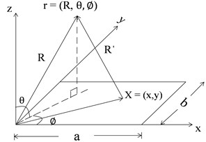
It is assumed that the rectangular thin plate, clamped along at four edges in flexural vibration is set on a flat rigid baffle of infinite extent as shown in Fig. 1. The complex acoustics pressure amplitude p(r) at position r(R,θ,∅) can be written in terms of the plate surface velocity using the Rayleigh integral [14] evaluated over the plate surface is given by Eq. (1):
where, vx is complex velocity amplitude normal to the surface at location X=(x,y), k is acoustics wave number, ρ is density of air, c is speed of sound, R'=|r-X|, distance from the location on the plate to the observation point and R is radius of sphere. The term e-jkR'/R' is Half space Green’s function [15].
Fig. 1Co-ordinate system of a vibrating plate
By integrating the far-field acoustic intensity over a hemisphere of radius R, the total acoustic power [16] is given by Eq. (2):
The velocity V(x,y) at any location X on the plate can be found by summing over all the modes of structure vibration of plate [15] and is given by Eq. (3):
By substituting Eq. (3) into Eq. (1), the sound pressure is given by:
Thus, substituting the mode shape function of the plate with clamped boundary conditions into Eq. (4), the complex acoustic pressure amplitudes P(r) is given by Eq. (5):
where:
An analytical solution of Amn [17] is given by Eq. (6):
where:
α=kasinθcos∅,β=kbsinθsin∅.
The total acoustic power is given by Eq. (7):
where, m' and n' denote the value of m and n in conjugate form.
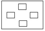
In this paper, sound power radiated from a plate having varying thickness (different taper ratio 0.3, 0.6 and 0.9) with discrete patches and point masses is analysed. Two arrangements of plate with attached discrete patches and point masses are considered. Plate with patches is shown in Fig. 2(b)-(d). Plate with point masses is similar to that of Fig. 2(b)-(d), when patches are replaced by equivalent point masses. The selection of point mass and patch is such that mass of (plate + patch) is equal to (plate + point mass).
2.2. Configuration and material properties of plate and patches:
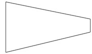
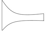
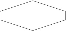
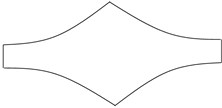
The dimensions and the physical properties of plate and patch are shown in Table 1. Four different variable thicknesses [18] of plate are considered for analysis. The variation of the thickness is shown in Fig. 3, where thickness is varied linearly and linearly increasing-decreasing for case 1 and 3 while thickness is varied parabolically and parabolically increasing-decreasing for case 2 and 4. In all four cases, mass of the plate and width of the plate are kept constant.
Fig. 2a) Plate without any discrete patch / point mass; b) plate with single patch, mass of patch = 0.1 times plate mass; c) plate with two discrete patches, mass of each patch = 0.05 times plate mass; d) plate with four discrete patches, mass of each pat patch = 0.025 times plate mass
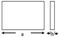
a)
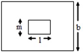
b)
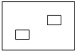
c)
d)
Table 1The dimension and the physical properties of plate and patch
Dimensions | Plate (Fig. 2(a)) | Single patch (Fig. 2(b)) | Two patch (Fig. 2(c)) | Four patch (Fig. 2(d)) |
Length [m] | a= 0.455 | l=0.11375 | l=0.07583 | l=0.05678 |
Width [m] | b= 0.379 | m=0.0631 | m=0.04737 | m=0.03158 |
Thickness [m] | h= 0.003 | n= 0.007 | n= 0.007 | n=0.007 |
Density [kg/m³] | 7850 | 7850 | 7850 | 7850 |
Young’s modulus [N/m²] | 2.10E+11 | 2.10E+11 | 2.10E+11 | 2.10E+11 |
Poisson ratio | 0.3 | 0.3 | 0.3 | 0.3 |
Fig. 3Plate with different variable thickness.
a) Case 1
b) Case 2
c) Case 3
d) Case 4
The Eq. (8) of different types of thickness variation are given by [13]:
where, hX is the thickness of plate at x- distance, n= 1 for linear profile and n= 2 for parabolic profile and HX is the taper parameter which is defined as HX=(1-hmin/hmax). Eq. (8) represents decreasing thickness variation for linear and parabolic profile (case 1 and 2). Eq. (9) represents increasing-decreasing thickness variation for linear and parabolic profile (case 3 and 4). The total volume of plate is constant which is given by:
where h is the thickness of uniform plate and hX is represented in terms of hmax and HX. The taper parameters Hx taken are 0.3, 0.6 and 0.9.
3. Result and discussion
3.1. Validation of sound power calculation
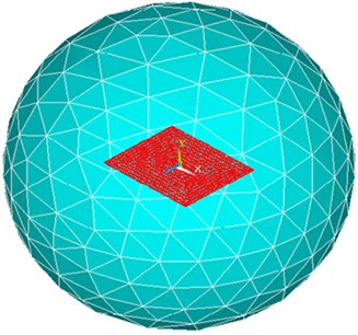
Finite element method (FEM) and Rayleigh integral for sound power calculation have been used. For modeling of plate, solid element 186 is used in ANSYS. For modeling the surrounding acoustic medium around the plate, FLUID30 and FLUID130 elements are used. FLUID30 is used to activate the fluid-structure interaction. The FLUID 130 elements are created on the surface of the outer sphere. This element simulates a condition of infinite space around the source thus eliminates the error due to reflection of sound waves back to the source. The number of elements and nodes created are approximately 39600 and 14400, respectively, after proper convergence of results for different cases. Figs. 4 and 5 represents the meshing diagram of rectangular plate and its surrounding.
Fig. 4Meshing diagram of plate
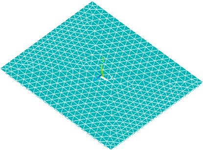
Fig. 5Meshing diagram of the plate surrounding
A mild steel simply supported rectangular isotropic plate of length a= 0.455 m, width b= 0.379 m and thickness h= 0.003 m is used for validation. Rectangular plate is simply supported and excited by a concentrated force of amplitude 1 N applied at the center of the plate. The plate is assumed to be vibrating in air with air density ρ= 1.21 kg/m3. The speed of sound ‘c’ in air is taken equal to 343 m/s. A structural damping coefficient of 0.01 is used for plate in air medium. For validation of sound power radiation from a rectangular plate, the published result of Li et al. [10] is considered as shown in Fig. 6. From the Fig. 6 it is clear that the obtained results are in good agreement with the published result.
Fig. 6Comparison of sound power level with that of Li et al. [10]
![Comparison of sound power level with that of Li et al. [10]](https://static-01.extrica.com/articles/16620/16620-img12.jpg)
3.2. Acoustics response analysis of plate with varying thickness with attached patches / point masses with different taper parameter (HX)
The sound power level (dB, reference = 10-12 W) of plate clamped along all the four edges with attached point masses and patches with different taper parameter (HX) is investigated. The plate is excited by a concentrated force of amplitude 1 N at the center of plate. A structural damping coefficient of 0.01 is used for plate in air medium. A frequency range of 10-1000 Hz is chosen in order to investigate the acoustic response analysis for different taper ratio (0.3, 0.6, and 0.9).
3.2.1. Case 1 (Linearly varying thickness)
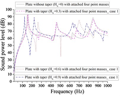
Figs. 7 and 8 compare the sound power level of (plate + one patch) and (plate + one-point mass) for different taper ratio. It is evident that one patch is more effective in achieving the minimum sound power level (22 dB) than one-point mass for plate without taper. As taper increases to HX= 0.6, one-point mass becomes effective in getting minimum sound power level in comparison to that of one patch due to modes contribution.
Fig. 7Comparison of sound power level (dB) of plate without taper (HX= 0) and with taper (HX= 0.3, 0.6, 0.9) with attached one patch for case 1
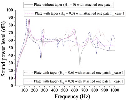
Fig. 8Comparison of sound power level (dB) of plate without taper (HX= 0) and with taper (HX= 0.3, 0.6, 0.9) with attached one-point mass for case 1
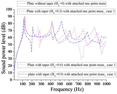
Fig. 9Comparison of sound power level (dB) of plate without taper (HX= 0) and with taper (HX= 0.3, 0.6, 0.9) with attached two patches for case 1
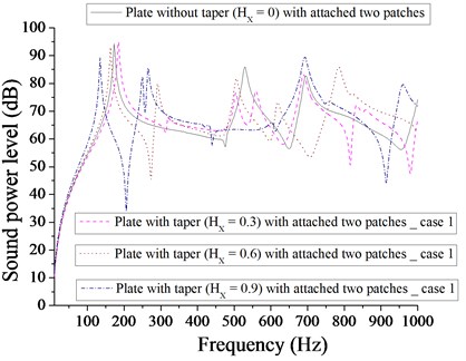
Fig. 10Comparison of sound power level (dB) of plate without taper (HX= 0) and with taper (HX= 0.3, 0.6, 0.9) with attached two point masses for case 1
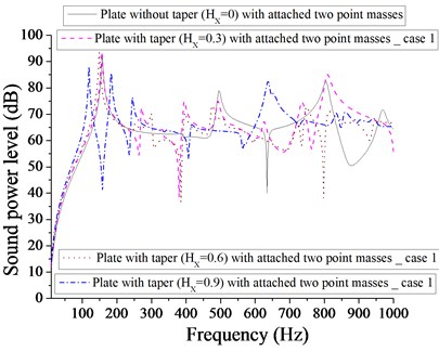
Figs. 9 and 10 compare the sound power level of (plate + two patches) and (plate + two point masses) for different taper ratio. Two patches with taper ratio of HX= 0.9 is more effective in achieving the minimum sound power level (34 dB) in comparison to that of two point masses with different taper ratio. It is clear from Fig. 10 that the minimum sound power level of plate with two point masses for different taper ratio (HX= 0, 0.3, 0.6 and 0.9) are 40, 39, 39 and 41 dB respectively at different corresponding frequencies 634, 380, 798 and 158 Hz. Obviously, these values are very close to each other. Therefore, we have the option of selection of different taper (at different frequencies) to achieve minimum sound power level. Figs. 11 and 12 show the sound power level of (plate + four patches) and (plate + four point masses) for different taper ratio. The minimum sound power level for plate with four patches is 33 dB for HX= 0.9 and minimum sound power level for plate with four point masses is 34 dB for HX= 0.6. It is quite evident that plate with four patches at HX= 0.9 is almost equally effective in comparison to four point masses at HX= 0.6. Out of Figs. 7-12, the minimum sound power level achieved is 22 dB for taper ratio, HX= 0 with one patch.
Fig. 11Comparison of sound power level (dB) of plate without taper (HX= 0) and with taper (HX= 0.3, 0.6, 0.9) with attached four patches for case 1
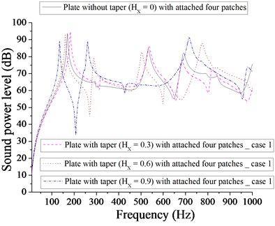
Fig. 12Comparison of sound power level (dB) of plate without taper (HX= 0) and with taper (HX= 0.3, 0.6, 0.9) with attached four point masses for case 1
3.2.2. Case 2 (Parabolic varying thickness)
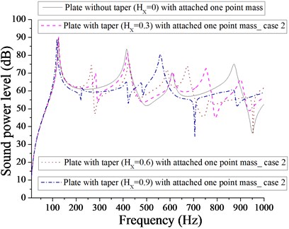
From Fig. 13, the minimum sound power level for one patch for parabolic varying thickness is 22 dB for taper ratio, HX= 0. The next minimum sound power level noted is 39 dB at HX= 0.9. Obviously, taper influences in obtaining the minimum sound power level. From Fig. 14, we get the minimum sound power level of approximately 35 dB for plate with HX= 0 and HX= 0.9. Clearly, one patch is more effective in achieving minimum sound power level in comparison to one-point mass. From Figs. 15 and 16, it is clear that with two patches and two point masses, the minimum sound power level achieved is almost equal to 36 dB.
Fig. 13Comparison of sound power level (dB) of plate without taper (HX= 0) and with taper (HX= 0.3, 0.6, 0.9) with attached one patch for case 2
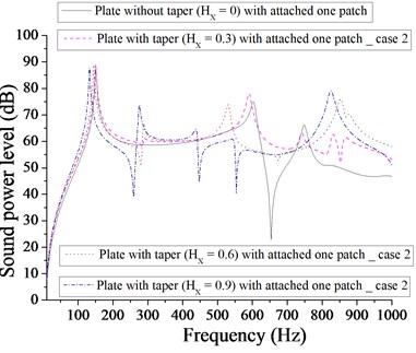
Fig. 14Comparison of sound power level (dB) of plate without taper (HX= 0) and with taper (HX= 0.3, 0.6, 0.9) with attached one-point mass for case 2
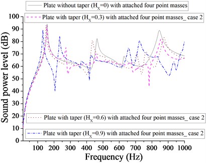
However, with two patches it occurs at HX= 0.9 and with two point masses, it occurs at HX= 0.6. It is obvious from Fig. 17 that minimum sound power level for plate with four patches is 35 dB at HX= 0.9 and from Fig. 18, the minimum sound power level is 40 dB at HX= 0.9. It is evident from Figs. 13-18 that plate with one patch with HX= 0 is most effective in achieving minimum sound power level for parabolic varying thickness. Redistribution of patches and point masses does not help in getting minimum sound power level for plate with parabolic varying with different taper ratio (HX= 0.3, 0.6, 0.9).
Fig. 15Comparison of sound power level (dB) of plate without taper (HX= 0) and with taper (HX= 0.3, 0.6, 0.9) with attached two patches for case 2
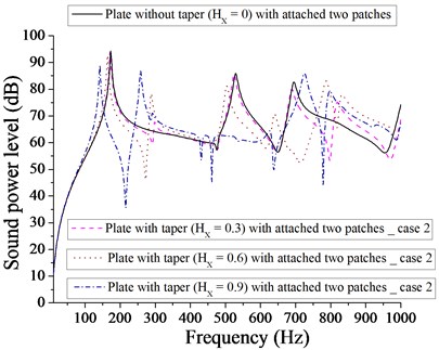
Fig. 16Comparison of sound power level (dB) of plate without taper (HX= 0) and with taper (HX= 0.3, 0.6, 0.9) with attached two point masses for case 2
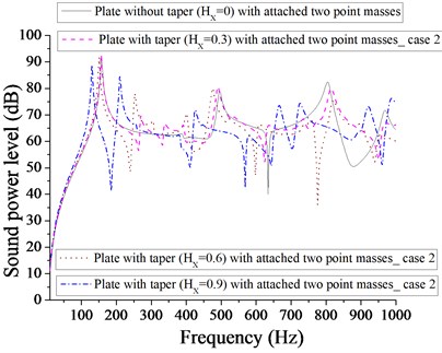
Fig. 17Comparison of sound power level (dB) of plate without taper (HX= 0) and with taper (HX= 0.3, 0.6, 0.9) with attached four patches for case 2
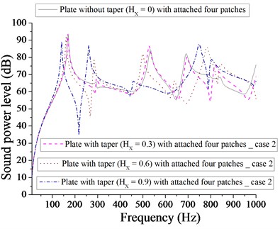
Fig. 18Comparison of sound power level (dB) of plate without taper (HX= 0) and with taper (HX= 0.3, 0.6, 0.9) with attached four point masses for case 2
3.2.3. Case 3 (Linearly increasing-decreasing varying thickness)
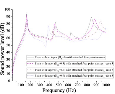
From Fig. 19, the minimum sound power level for plate with one patch and with linearly increasing – decreasing varying thickness, occurs at 22 dB at HX= 0, whereas the minimum sound power level for plate with one-point mass is reported at 35 dB at HX= 0 as shown in Fig. 20. Different taper ratio (HX= 0.3, 0.6 and 0.9) donot improve in getting the minimum sound power level with one patch or with one-point mass. From Fig. 21, it is apparent that the minimum sound power level for plate with two patches is at 50 dB at HX= 0.9, whereas the minimum sound power level for plate with two point masses is at 33 dB at HX= 0.3 at two different HX= 0.3 and 0.9 as shown in Fig. 22. From Figs. 21 and 22, it is clear that two point masses are more effective in achieving the minimum sound power level in comparison to two patches. Figs. 23 and 24 compare the sound power level for plate with four patches and four point masses. The minimum sound power level for plate with four patches is 33 dB at HX= 0.3 and minimum sound power level for plate with four point masses is 47 dB at HX= 0.9. Obviously four patches are more effective in achieving in minimum sound power level in comparison to four point masses. From Fig. 24, we get an interesting observation that for frequency band of approximately 450-950 Hz, the sound power level for plate with four point masses at HX= 0.9 is always lower in comparison to different taper ratio (HX= 0, 0.3 and 0.6). From Figs. 19-24, it is observed that plate with one patch without taper (HX= 0) is most effective in achieving minimum sound power level. Redistribution of patches and point masse, does not help in achieving minimum sound power level for plate with different taper ratio (HX= 0.3, 0.6 and 0.9).
Fig. 19Comparison of sound power level (dB) of plate without taper (HX= 0) and with taper (HX= 0.3, 0.6, 0.9) with attached one patch for case 3
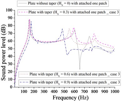
Fig. 20Comparison of sound power level (dB) of plate without taper (HX= 0) and with taper (HX= 0.3, 0.6, 0.9) with attached one-point mass for case 3
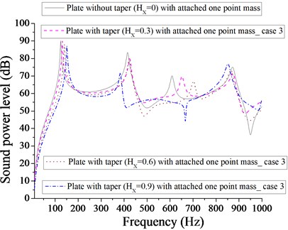
Fig. 21Comparison of sound power level (dB) of plate without taper (HX= 0) and with taper (HX= 0.3, 0.6, 0.9) with attached two patches for case 3
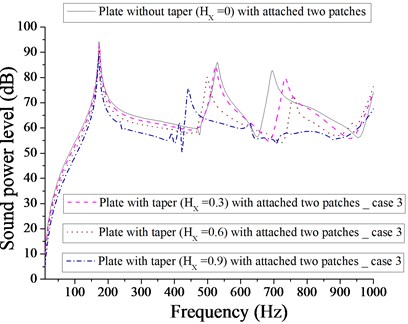
Fig. 22Comparison of sound power level (dB) of plate without taper (HX= 0) and with taper (HX= 0.3, 0.6, 0.9) with attached two point masses for case 3
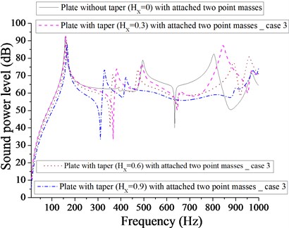
Fig. 23Comparison of sound power level (dB) of plate without taper (HX= 0) and with taper (HX= 0.3, 0.6, 0.9) with attached four patches for case 3
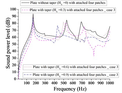
Fig. 24Comparison of sound power level (dB) of plate without taper (HX= 0) and with taper (HX= 0.3, 0.6, 0.9) with attached four point masses for case 3
3.2.4. Case 4 (Parabolic increasing–decreasing varying thickness)
From Fig. 25, it is observed that minimum sound power level for plate with one patch is 22 dB at HX=0, whereas from Fig. 26, it is noted that minimum sound power level for plate with one-point mass is 5 dB at HX= 0.3. For plate with two patches, minimum sound power level is 25 dB at HX= 0.3 as shown in Fig. 27. It is observed from Fig. 27 that we get a frequency band of approximately 500-850 Hz, where sound power level for HX= 0.9 (plate with two patches) is always lower for other taper ratio (HX= 0, 0.3 and 0.6). From Fig. 28, it is clear that minimum sound power level for plate with two point masses is approximately 30 dB for two taper HX= 0.3 and 0.9. From Fig. 29, it is noted that minimum sound power level for plate with four patches is 42 dB at HX= 0.6, whereas for plate with four point masses, the minimum sound power level is 40 dB at HX= 0.3 as shown in Fig. 30.
Fig. 25Comparison of sound power level (dB) of plate without taper (HX= 0) and with taper (HX= 0.3, 0.6, 0.9) with attached one patch for case 4
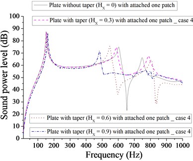
Fig. 26Comparison of sound power level (dB) of plate without taper (HX= 0) and with taper (HX= 0.3, 0.6, 0.9) with attached one-point mass for case 4
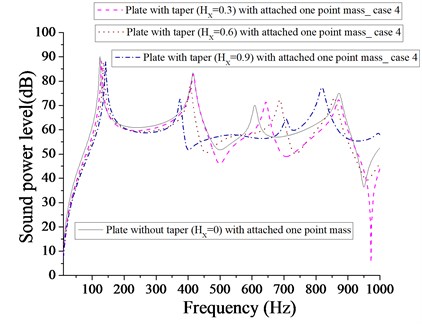
Obviously four patches or four point masses do not affect significantly in getting minimum sound power level. However, for plate with four point masses, we get a frequency band of approximately 650-930 Hz, where sound power level with HX= 0.9 is always lower than that of other taper ratio (HX= 0, 0.3 and 0.6). Out of above case (parabolic increasing – decreasing) considered, as evident from Figs. 25 – 30, one-point mass, is more effective in getting minimum sound power level of 5 dB at HX= 0.3 in comparison to different taper (HX= 0, 0.6 and 0.9) and masses/patches arrangements.
Fig. 27Comparison of sound power level (dB) of plate without taper (HX= 0) and with taper (HX= 0.3, 0.6, 0.9) with attached two patches for case 4
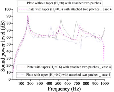
Fig. 28Comparison of sound power level (dB) of plate without taper (HX= 0) and with taper (HX= 0.3, 0.6, 0.9) with attached two point masses for case 4
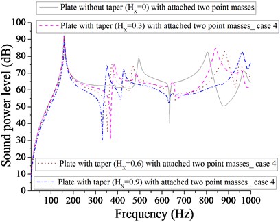
Fig. 29Comparison of sound power level (dB) of plate without taper (HX= 0) and with taper (HX= 0.3, 0.6, 0.9) with attached four patches for case 4
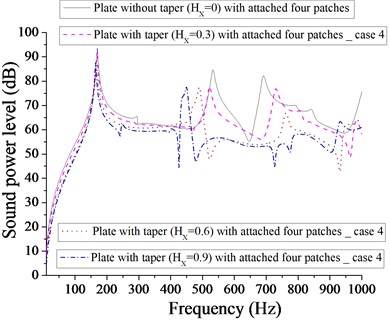
Fig. 30Comparison of sound power level (dB) of plate without taper (HX= 0) and with taper (HX= 0.3, 0.6, 0.9) with attached four point masses for case 4
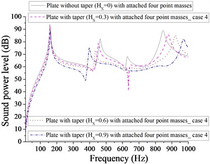
3.2.5. Peak sound power level variation with different taper ratio for all the cases
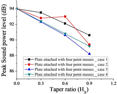
Figs. 31-36 show the variation of peak sound power level with different taper ratio for plate with patches and point masses for all the cases (1, 2, 3 and 4 as shown in Fig. 3). Plate with four patches with linearly increasing – decreasing thickness variation (case 3 as shown in Fig. 3) at HX = 0.3 is most effective in achieving minimum peak sound power level (82 dB). It if further observed from Fig. 35 that for a wider range of taper ratio i.e. (HX= 0.15-0.45), plate with four patches with linearly increasing – decreasing thickness variation remains a choice for getting minimum peak sound power level (85 dB) for all the cases considered. For taper ratio HX= 0.6, the most effective arrangement in getting minimum peak sound power level is plate with one patch with parabolic increasing – decreasing thickness variation (as shown in Fig. 31).
Fig. 31Variation of peak sound power level without taper (HX= 0) and with different taper ratio taken for plate with one patch for case 1, 2, 3 and 4
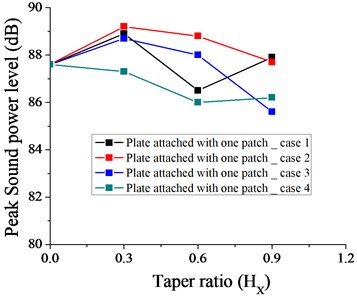
Fig. 32Variation of peak sound power level without taper (HX= 0) and with different taper ratio taken for plate with one-point mass for case 1, 2, 3 and 4
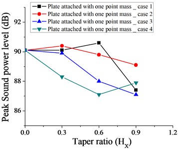
Fig. 33Variation of peak sound power level without taper (HX= 0) and with different taper ratio taken for plate with two patches for case 1, 2, 3 and 4
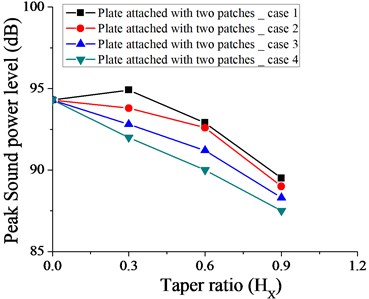
Fig. 34Variation of peak sound power level without taper (HX= 0) and with different taper ratio taken for plate with two point masses for case 1, 2, 3 and 4
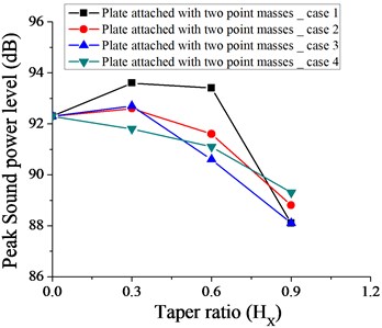
Fig. 35Variation of peak sound power level without taper (HX= 0) and with different taper ratio taken for plate with four patches for case 1, 2, 3 and 4
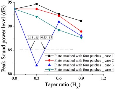
Fig. 36Variation of peak sound power level without taper (HX= 0) and with different taper ratio taken for plate with four point masses for case 1, 2, 3 and 4
4. Conclusions
The sound radiation due to vibration of clamped plate with different taper ratio with attached discrete patches and point masses is investigated. The mass of the (plate + patches) and (plate + point masses) are kept constant and equal. The minimum sound power level (5 dB) achieved is for plate with one-point mass with parabolic increasing – decreasing thickness variation at HX= 0.3. Minimum peak sound power level of 82 dB is obtained for plate with four patches with linearly increasing – decreasing thickness variation at HX= 0.3. For minimum peak sound power level (85 dB), wider variation of HX (0.15-0.45) for plate with four patches with linearly increasing – decreasing thickness variation is possible.
References
-
Appl F. C., Byers N. R. Fundamental frequency of simply supported rectangular plates with linearly varying thickness. Journal of Applied Mechanics, Vol. 205, 1965, p. 163-167.
-
Raju B. B. Vibration of thin elastic plates of linearly variable thickness. International Journal of Mechanical Engineering Sciences, Vol. 8, 1966, p. 89-100.
-
Kuttler J. R., Sigillito V. G. Vibrational frequencies of clamped plates of variable thickness. Journal of Sound and Vibration, Vol. 86, 1983, p. 181-189.
-
Bert C. W., Malik M. Free vibration analysis of tapered rectangular plates by differential quadrature method: a semi – analytical approach. Journal Sound and Vibration, Vol. 190, 1996, p. 41-63.
-
Akiyama K. Fundamental frequencies of rectangular plates with linearly varying thickness. Journal of Sound and Vibration, Vol. 205, 1997, p. 380-384.
-
Huang M., Ma X. Q., Sakiyama T., Matuda H., Morita C. Free vibration analysis of orthotropic rectangular plates with variable thickness and general boundary conditions. Journal of Sound and Vibration, Vol. 288, 2005, p. 931-955.
-
Atalla N., Nicoals J., Gauthier C. Acoustic radiation of an unbaffled vibrating plate with general elastic boundary conditions. The Journal of the Acoustical Society of America, Vol. 99, 1996, p. 1484-94.
-
Maidanik G. Response of ribbed panels to reverberant acoustic field. The Journal of the Acoustical Society of America, Vol. 34, 1962, p. 809-826.
-
Laulagnet B. Sound radiation by a simply supported unbaffled plate. The Journal of the Acoustical Society of America, Vol. 103, 1998, p. 2451-2462.
-
Li Sheng, Li Xianhui The effects of distributed masses on acoustic radiation behavior of plates. Applied Acoustics, Vol. 69, 2008, p. 272-279.
-
Putra A., Thompson D. J. Sound radiation from rectangular baffled and unbaffled plates. Applied Acoustic, Vol. 71, 2010, p. 1113-1125.
-
Jeyaraj P. Vibro-acoustic behavior of an isotropic plate with arbitrarily varying thickness. European Journal of Mechanics A/Solids, Vol. 29, 2010, p. 1088-1094.
-
Nelisse H., Beslin O., Nicolas J. A generalized approach for the acoustic radiation from a baffled or unbaffled plate with arbitrary boundary conditions immersed in a light or heavy fluid. Journal of Sound and Vibration, Vol. 211, 1998, p. 207-225.
-
Rayleigh L. The Theory of Sound. 2nd Edition, 1896.
-
Fahy F. J., Gardonio P. Sound and Structural Vibration: Radiation, Transmission and Response. 2nd Edition, Academic Press, London, 2006.
-
Thomson D. J., Xi G., Jones C. J. C. The radiation efficiency of baffled plate and strips. Journal of Sound and Vibration, Vol. 280, 2005, p. 181-209.
-
Wallace C. E. Radiation resistance of a rectangular panel. The Journal of the Acoustical Society of America, Vol. 51, 1972, p. 946-952.
-
Roy P. K., Ganesan N. Studies on the response of a square plate with variable thickness excited by uniformly distributed load. Computers Structures, Vol. 45, 1992, p. 593-603.
About this article
Bipin Kumar – research scholar under the guidance of Vinayak Ranjan. Vinayak Ranjan – overall supervision and guidance. K. Priya Ajit – contributing in analytical analysis of model. Mohammad Sikandar Azam – contributing in finite element modeling. Ranjan Kumar – contributing in finding results.

