Abstract
Aimed to solve the problem of weak anti-resonance performance and poor working stability in current anti-resonance vibrating machines, this paper presents a nonlinear dynamic model that reflects the actual working state of the anti-resonance machine. Under the material mass fluctuation condition, the dynamic response of the anti-resonance vibrating system has been discussed, and the dynamic parameters selection problem of the anti-resonance vibrating system has been analyzed which could be used to improve working performance stability. In the paper, the influence of nonlinear factors of the anti-resonance vibrating machine on the driving body and the working body has been analyzed under the material fluctuation conditions also. The results can provide the theoretical support and experimental basis for improving the design and working performance of the anti-resonance vibrating machine.
1. Introduction
Vibration machine is a kind of mechanical equipment which used to carry out all kinds of technological processes by vibration motion, such as vibration conveyor, vibration screen, vibration dryer and so on [1]. To design the vibration machine, two problems must be considered that the first is the vibration frequency and the vibration response amplitude must meet the requirement of the vibration system; the next is to reduce the vibration action on the foundation and to reduce the working noise pollution to the environment. Above, the two problems look like paradoxical, but can be effectively solved by using the anti-resonance theory [2-4]. In the literature [5], the viewpoint that to design the vibration machine based on the anti-resonance principle had been put forward, and the two kinds of anti-resonance vibrating machines include the origin anti-resonance machine and the cross-point anti-resonance machine had been presented. The vibration exciters of the two types of anti-resonance machines were not installed on the working body of the vibrating machine, but to install on the driving body, namely installed on the lower body of the vibrating machine. So the excitation source of the two kinds of anti-resonance machine did not participate vibrating motion with the vibration system, which made the structure of the working body greatly simplified, and the mass of vibration can be reduced about 30 %-50 % [6-8]. Because of the exciting force did not directly act to the working body of the two kinds of anti-resonance machine, the machine life can be improved obviously. And because the lower body of the vibrating machine was almost no vibration, to guarantee the stiffness and strength requirements of the vibrating machine in the design process was easier, and the excitation device can be designed according to the static load, the noise of the whole machine can be significantly reduced.
However, the excited frequency of the anti-resonance vibration machine is requested particularly stable in the practical application, or the anti-resonance point of the anti-resonance vibrating machine may be deviate because of the fluctuation of the material mass, and the amplitude of the vibration response will change also, which will reduce the working performance of the vibrating machine [9, 10]. Therefore, it is very important to improve the vibration amplitude stability of the upper body and lower body by revealing the relationship between the resonance point, the anti-resonance point and the mass ratio, and to select the appropriate dynamic parameters. Know from the relevant literatures that can be consulted [11-13], that the design of anti-resonance vibrating machine have a certain blindness currently, because of a large number of dynamic parameters have been related to the anti-resonance vibrating machine, and there are no research literatures have solved the difficult problem that the dynamic parameters how to influence the mechanical characteristics of anti-resonance vibrating machine. In the paper, by multiple scales method and based on the existing anti-resonance test prototype, the problem that how to select the dynamic parameters to make the working body amplitude of the anti-resonance vibrating machine to stabilize at the design value and the driving body amplitude is the smallest under the conditions of material mass fluctuation had been researched. And the influence of different systemic parameters and material mass fluctuation on the vibration response of the anti-resonance vibrating machine has been discussed. All the research results are helpful to improve the working performance and design level of this kind of anti-resonance vibrating machine.
2. Dynamic model of nonlinear anti-resonance vibrating machine
The dynamic model that shown as Fig. 1 abstract from the existing anti-resonance test prototype in laboratory that shown as Fig. 2. In which, is the working body mass of the anti-resonance vibrating machine which include the upper body mass of vibrating machine and the load material mass, is the driving body mass of the anti-resonance vibrating machine which include lower body mass of vibrating machine and the exciters mass (the reverse synchronous rotary inertia vibration exciters were fixed on the lower body), is the excited force which shown as Fig. 1, and is the excited frequency.
Fig. 1Dynamic model of nonlinear anti-resonance vibrating system that driven by dual rotors
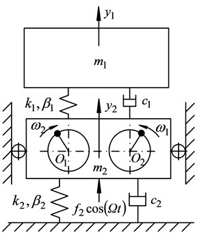
Based on D’Alembert’s principle, the dynamic equations of the nonlinear anti-resonance vibrating system that shown as Fig. 1 can be expressed as:
where, and are vibration response displacement of upper body and lower body of the vibrating machine. According to the design and operational requirement of this kind of anti-resonance vibrating machine, to select the rubber spring to be the main vibration spring and the supporting spring, to set and is the linear dynamic stiffness coefficient and the equivalent damping coefficient of main vibration spring in direction, to set and is the linear dynamic stiffness coefficient and the equivalent damping coefficient of supporting spring in direction, and to set and is the three times nonlinear stiffness coefficient of main vibration spring and supporting spring in direction (where, and are constant which related to the spring material ) [14, 15].
In order to decouple Eq. (1), to select the vibration modal matrix to make . And then to orthogonal process Eq. (1), to transform the physical coordinate quantity of Eq. (1) into the modal coordinate quantity:
where, and are the natural frequency of the anti-resonance vibrating system that shown as Fig. 1.
Set (1, 2 and 1, 2) and (1, 2 and 1, 2, 3, 4), where is the small parameters. Then set:
where, , .
Based on the multiple scales method of nonlinear vibration systems [16, 17], to perturbation analyze the modal equations Eq. (2), then the displacement response expression of Fig. 1 anti-resonance vibrating system can be obtained as:
where:
is the tuning parameter of the multiple scales method:
where, is the complex conjugate of the first two terms.
3. Perturbation analysis of material mass fluctuation
Using the random perturbation analysis method to research the dynamic response of the anti-resonance vibrating machine that shown as Fig. 1 under the material mass fluctuation condition. Set the mass of the upper body is:
where, is the deterministic mass part of the upper body, is the zero mean random mass part of material, is the small parameter, is the zero mean random variable, is the zero mean random fluctuation of material mass.
To analyze the vibrating responses of the nonlinear anti-resonance system which described by Eq. (10) and Eq. (11), the physical meaning of the analysis results were not obvious. So in order to discuss the influence factors of vibration response of the vibrating system under the anti-resonance state and the condition of material mass fluctuation, based on the design parameters of the existing anti-resonance test prototype, and the general practice for dynamic parameters selection of anti-resonance vibrating system [18], set , and let them into the nonlinear anti-resonance equations that described by Eq. (1). Then lead Eq. (1), and Eq. (3)-Eq. (8) into Eq. (10) and Eq. (11), the approximate linear vibration response of Eq. (1) vibrating system can be gotten as:
where, is the determining part of the amplitude of the working body of the anti-resonance vibrating system that shown as Fig. 1, is the amplitude of the driving body of the anti-resonance vibrating system. Aimed to the fluctuation mass of the material on the upper body, set the standard deviation is , then the random partial variance of working body amplitude under the condition of material mass fluctuation can be expressed as:
where, is the vibrating response phase of the working body:
Therefore, by discussing the amplitude (including and the random partial variance of the working body amplitude) and the amplitude , the paper can be used to research the dynamic response problem of the nonlinear anti-resonance vibrating machine that shown as Fig. 1, under the condition of the random fluctuation of material mass.
4. Response analysis and dynamic parameters selection
In the design process of the anti-resonance vibrating machine, the working body mass , the driving body mass , the spring dynamic stiffness coefficient and the equivalent damping coefficient would be determined by the design conditions and working conditions, which were difficult to be adjusted during the working process of vibrating machine. So in order to ensure the amplitude stability of the working body and driving body of the anti-resonance vibrating machine, and the amplitude of the driving body is the least, the paper will select different dynamic parameters combinations of the upper body and the lower body, to research the effects on the vibration response of the anti-resonance vibrating system under the conditions of material mass fluctuation.
Then introducing the following symbols to non-dimensional treat Eq. (13) and Eq. (14): is natural frequency of the working body, which is defined as the anti-resonance frequency of the anti-resonance vibrating system, is natural frequency of the driving body, is the mass ratio of the working body and the driving body, is the mass ratio of the material fluctuation mass and deterministic mass part of the working body, is the frequency ratio, is the anti-resonance frequency ratio, is the damping ratio of working body, is the damping ratio of driving body, is the support spring static deformation of driving body, is the dynamic amplification factor of working body, is the dynamic amplification factor of driving body.
Based on the dual rotors anti-resonance test prototype in laboratory that shown as Fig. 2, to select the structural parameters as follows:
Fig. 2Dual rotors anti-resonance test prototype
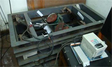
Set 160 kg, 128 kg, 1.25, and the material mass fluctuation range ±32 kg, 300 kN/m, 700 kN/m, 0.55, 200 N. According to design principles of anti-resonance vibrating machine, to set the excited frequency locate in the vicinity of anti-resonance frequency of the vibrating system. During the course of the vibrating machine working, the material mass fluctuates, which will cause the drift of anti-resonance frequency point of the anti-resonance system. So to set the target working amplitude of the working body is 5.0 mm. Then to research the vibration response of the upper body and the lower body of the anti-resonance vibrating machine that shown as Fig. 2, when the anti-resonance frequency ratio 2, 2.5 and 3.
According to the experimental data of the anti-resonance vibrating machine that shown as Fig. 2, to calculate the mechanical characteristic parameters which expressed in Table 1.
Table 1Dynamic parameters table of anti-resonance vibrating system
Parameters | |||||||||
Before material mass fluctuation | After material mass fluctuation | After excited frequency adjustment | Before material mass fluctuation | After material mass fluctuation | After excited frequency adjustment | Before material mass fluctuation | After material mass fluctuation | After excited frequency adjustment | |
/ kg | 160 | 192 | 192 | 160 | 192 | 192 | 160 | 192 | 192 |
1.250 | 1.38 | 1.38 | 1.31 | 1.44 | 1.44 | 1.50 | 1.66 | 1.66 | |
/ (rad/s) | 43.30 | 40.57 | 40.57 | 43.30 | 40.57 | 40.57 | 43.30 | 40.57 | 40.57 |
2.0 | 1.944 | 1.944 | 2.50 | 2.601 | 2.601 | 3.0 | 2.877 | 2.877 | |
(rad/s) | 83.773 | 83.773 | 76.967 | 83.773 | 83.773 | 74.902 | 83.773 | 83.773 | 73.714 |
0.419 | 0.407 | 0.422 | 0.221 | 0.197 | 0.202 | 0.183 | 0.179 | 0.184 | |
0.0377 | 0.0619 | 0.0355 | 0.0284 | 0.0401 | 0.0290 | 0.0139 | 0.0242 | 0.0143 | |
/ mm | 5.0 | 4.47 | 4.92 | 5.0 | 4.59 | 5.02 | 5.0 | 4.53 | 4.96 |
/ mm | 0.735 | 0.899 | 0.740 | 0.730 | 0.902 | 0.737 | 0.731 | 0.910 | 0.739 |
Analyze the Table 1 to know that, when the load of the working body fluctuates from no load to full load, the amplitude of working body decrease change, but the decreased amplitude is less than or equal to 0.55 mm, namely the reduction ratio less than 10 %, which meet the initial design goal conditions 5.0 mm of the anti-resonance vibrating machine that show as Fig. 2, namely the amplitude remains almost unchanged under the material mass fluctuation. So, when selecting the mechanical characteristic parameters from Table 1, the working state of the vibrating machine is hardly affected by the material mass fluctuation. Table 1 also reflects that, the amplitude of the lower body increase change, and the increased amplitude is less than or equal to 0.25 mm, but which cause the dynamic load that pass to the foundation increases significantly. To calculate the dynamic load value to know that the increase value of dynamic load is less than or equal to 775 N, and comparing with design and using conditions of this kind of vibrating machine [4, 18] which is in the scope of allow.
During the experiment, to adjust the rotational speed of driving system in the real time to make the excited frequency back to the near zone of the anti-resonance frequency, and then know from the Table 1 that, the vibrating response of upper body and lower body come back to almost the same state as system no load (Refer the excited frequency adjustment in Table 1). Therefore, during the actual use of the anti-resonance vibrating machine, in order to achieve the amplitude stability of working body, the rotational speed of excited motors must be adjusted, to make them track the drift of anti-resonance frequency point.
Now set the anti-resonance frequency ratio 2.5 of anti-resonance test prototype that shown as Fig. 2, and refer to the Table 1 to select the dynamic parameters of the anti-resonance test prototype, then the working process state of the test prototype can be detected, and the anti-resonance response photo under no-load condition can be expressed as Fig. 3(a). Know from the vibrating response curves that shown as Fig. 3(b), that the working body can maintain steady state vibration with vibrating amplitude of approximately 5.0 mm and the driving body can maintain quiver motion with vibrating amplitude of approximately 0 mm (the actual measured value of vibrating amplitude 0.7 mm, which far less than the vibrating amplitude of the driving body of the traditional vibrating machine [4, 18]). All indicate that the anti-resonance test prototype shown as Fig. 2 has good anti-resonance effect with the dynamic parameters shown as Table 1 under no-load conditions.
Fig. 3Vibrating response signal of the anti-resonance test prototype under no-load conditions
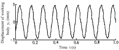
a) Vibrating response signal of working body
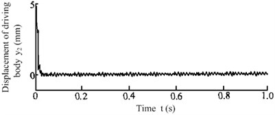
b) Vibrating response signal of driving body
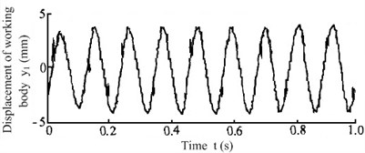
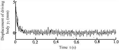
Fig. 4Vibrating response signal of the anti-resonance test prototype under 20 % load increase conditions
a) Vibrating response signal of working body
b) Vibrating response signal of driving body
When the test prototype was exerted 20 % loads which shown as Fig. 4(a), the actual measured vibrating response curves could be obtained as Fig. 4(b). The vibrating amplitude of working body reduced to about 4.5 mm, and the vibrating amplitude of driving body increased to about 1 mm. Now compare the vibrating response curves with the literature [1] to know that, although the material mass fluctuations have a great influence on the working state of the anti-resonance vibrating system, the anti-resonance vibrating machine that shown as Fig. 2 still has good anti-resonance working state. Comparing the curves in Fig. 3(b), Fig. 4(b) and the analysis data in Table 1 to know that, the experimental results can perfectly agreement with the theoretical analysis, and the correctness of the theoretical deduction conclusion in the paper can be verified.
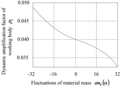
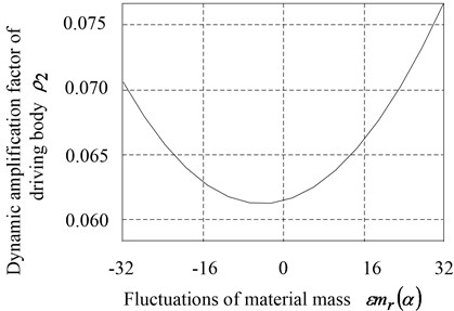
In order to discuss the effect of material mass change on the amplitude response of the anti-resonance vibrating machine, according to Table 1, to select the common used characteristic parameters 2.5 and 1.44 under the actual working conditions, to calculate the relationship between the dynamic amplification factors and of working body and driving body and the fluctuations of material mass when fluctuates from –32 kg to 32 kg, namely the working body mass fluctuate within the range ±20 %. The analysis results curves were shown as Fig. 5.
Fig. 5Relationship between the dynamic amplification factors and the fluctuations of material mass
a) Dynamic amplification factor of working body
b) Dynamic amplification factor of driving body
Know from Fig. 5(a) that, presented a decreasing and tending to remain stable. It indicated that the positive fluctuation of the material mass average value could help to cut the influence on working body vibration response of anti-resonance vibrating machine which caused by material mass fluctuation. With the positive increase of the material mass fluctuation, the dynamic amplification factor of working body decreased. Conversely, the influence on the dynamic amplification factor of the working body increased gradually, because of the negative material mass fluctuated. Hence, in order to ensure the working body had the stable desired amplitude, the designed mass of material should be small and it was limited in the appropriate range, when to design this kind of anti-resonance vibrating machine that shown as Fig. 2. Know from Fig. 5(b) that, whether the material mass was forward fluctuating or negative fluctuating, the material mass fluctuation would enhance the influence on the vibrating response amplitude of driving body, which could cause the dynamic amplification factor of driving body to increase change. It would decrease the vibration isolation effect of the anti-resonance vibrating machine. So the fluctuate range of material mass of anti-resonance vibrating system should be limited. And the computer control should be introduced, to adjust the excited frequency of driving system real-time to track the anti-resonance frequency point of the anti-resonance vibrating machine according to the fluctuation of material mass, which would make the vibrating amplitude response of driving body to be the smallest [19, 20].
Although during the practical applications of most anti-resonance vibrating machines, the nonlinear factors influence may be ignored, the nonlinear response phenomenon do exist, in some cases they are not negligible. So, according to the displacement response Eq. (10) and Eq. (11), the amplitude frequency response curves of Fig. 2 anti-resonance vibrating machine with different nonlinear stiffness coefficients have been researched which shown as Fig. 6.
Analyze Fig. 6 to know that, when 0, the vibrating response of the anti-resonance vibrating system should follow the linear change law, namely when analyzing the vibrating response of the anti-resonance system, the three nonlinear term influencing factors of the spring could be ignored. When 0, if the anti-resonance frequency of the vibrating system equals to excited frequency, the amplitude of driving body is zero (which shown as Fig. 6(b)). When 0, the nonlinear influencing factors enhanced significantly, the vibrating response amplitude of working body and driving body emerged bifurcation phenomenon, and it enhanced with the increase of excited frequency. Know from Fig. 6 that, when 0, whether the mean value of material mass fluctuation increase or decrease, the bifurcation mutation amplitude response of working body and driving body were much larger than the condition of material mass was stable. Therefore, aiming to the nonlinear anti-resonance vibrating machine in case of fluctuation of material mass, the working excited frequency should be make to stabilize in a small area near the anti-resonance frequency of the anti-resonance vibrating machine. And the excited frequency fluctuation should be tried to keep located in the left area of anti-resonance frequency, to avoid the bifurcations phenomenon of the amplitude response, because which should affect the vibrating response stability of the anti-resonance system seriously [21, 22]. In Fig. 6, with the increasing change of material mass, the mass of upper body would be changed, which caused the amplitude of working body and driving body increasing slightly, but the anti-resonance frequency would decrease also. Which lead to the minimum of driving body vibrating response curve that shown as Fig. 6(b) moved to left. Consequently, under the premise of meeting the anti-resonance requirements during working, the excited frequency of the vibrating machine should be decreased, to keep the amplitude of working body stable and the amplitude of driving body was least.
Fig. 6Effect of the nonlinear spring stiffness coefficients on the amplitude frequency response of the anti-resonance vibrating system
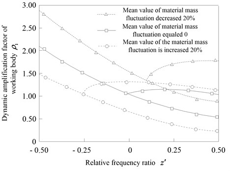
a) Effect of the nonlinear spring stiffness coefficients on working body
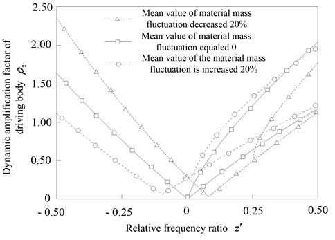
b) Effect of the nonlinear spring stiffness coefficients on driving body
5. Conclusions
This paper presented a nonlinear dynamic model of anti-resonance vibrating machine under the condition of material mass fluctuation. The multi-scale method and perturbation analysis were used to analyze the nonlinear dynamic behavior of the anti-resonance vibrating machine in the case of three term nonlinear spring stiffness. And the relationship among the dynamic parameters of the anti-resonance vibrating machine had been simplified analyzed also.
The fluctuation of material mass can lead to a drift of anti-resonance point of the anti-resonance vibrating machine. When the material mass increases, the anti-resonance frequency is smaller than the original anti-resonance frequency. On the left side of anti-resonance frequency, the vibration response of the anti-resonance vibrating system follows the linear changing law so that the nonlinear influence can be ignored. However, on the right side of anti-resonance frequency, as the frequency increases, the nonlinear influence will increase significantly, and the vibrating response amplitude will emerge bifurcation phenomenon. In addition, with the increasing of the excited frequency, the amplitude at the bifurcation point will also increase. Since the change of the material mass may lead the vibration response of the anti-resonance system to vibrate between linear and nonlinear performance, resulting in abnormal fluctuations of the amplitude of working body and driving body, the material mass should be kept stable during the working process of the anti-resonance machine.
In order to keep the vibration response stability of the anti-resonance vibrating system, the excited frequency should be limited into a little bit less than the original anti-resonance frequency, so that anti-resonance vibrating machine could have a good anti-resonance performance. Otherwise, the vibrating system will show a strong non-linear response, which may seriously affect the working performance of the anti-resonance system. The research results have huge guidance significance for design and application of the anti-resonance vibrating machines, and it is much helpful to improve current working performance of the anti-resonance vibrating machine.
References
-
Wen B. C., Li Y. N., Zhang Y. M., et al. Vibration Utilizing Engineering. Science Press, Beijing, 2005.
-
Liu J., Hou X. L. Application of anti-resonance theory of shock-absorption. Journal of Northeastern University (Natural Science), Vol. 15, Issue 4, 1994, p. 363-367.
-
Gong S. C. Application of anti-resonance method. Journal of Qufu Normal University, Vol. 31, Issue 2, 2005, p. 73-76.
-
Wen B. C., Liu S. Y., He Q. Theory and Dynamic Design Method of Vibrating Machine. China Machine Press, Beijing, 2002.
-
Liu J., Sun G. F. Theory of anti-resonant vibrating machine with application. Journal of Northeastern University (Natural Science), Vol. 16, Issue 1, 1995, p. 82-86.
-
Hanson D., Water T. P., Thompson D. J., et al. The role of anti-resonance frequencies from operational modal analysis in finite element model updating. Mechanical Systems and Signal Processing, Vol. 21, Issue 1, 2007, p. 74-79.
-
Kazuto S. Dynamic Vibration Absorber and its Applications. Corona Publishing Co., Ltd., Tokyo, 2010.
-
Sun Z. C. The application of anti-resonance theory in design of vibration absorbers. Chinese Journal of Applied Mechanics, Vol. 10, Issue 4, 1993, p. 97-103.
-
Horssen W. T., Pischanskyy O. V., Dubbeldam J. L. A. On the forced vibrations of an oscillator with a periodically time-varying mass. Journal of Sound and vibration, Vol. 329, Issue 6, 2010, p. 721-732.
-
Zhu Y., Wang S. L. Analytical solution for vibration system with time-varying mass. Journal of Vibration and Shock, Vol. 27, Issue 11, 2008, p. 160-163.
-
Wahl F., Schmidt L., Forrai L. On the significance of anti-resonance frequencies in experimental structure analysis. Journal of Sound and Vibration, Vol. 219, Issue 3, 1999, p. 379-394.
-
Liu J. T., Liu J., Li X. H., et al. Selection of parameters of an anti-resonant vibrator anti-resonant point just at the midpoint between two resonant points. Journal of Northeastern University (Natural Science), Vol. 30, Issue 3, 2009, p. 405-408.
-
Kim S., Singh R. Vibration transmission through an isolator modeled by continuous system theory. Journal of Sound and Vibration, Vol. 248, Issue 5, 2001, p. 925-953.
-
Zhu S. J., Zhen Y. F., Fu Y. M. Analysis of nonlinear dynamics of a two-degree-of-freedom vibration system with nonlinear damping and nonlinear spring. Journal of Sound and Vibration, Vol. 271, Issues 1-2, 2004, p. 15-24.
-
Wang G. Y., Zhen G. T., Han C. Analytical and experimental study of coupling vibration of nonlinear connected beams. Journal of Vibration Engineering, Vol. 22, Issue 1, 2009, p. 41-47.
-
Chen S. H. Quantitative Analysis Method for Strongly Nonlinear Vibration Systems. Science Press, Beijing, 2007.
-
Ghayesh M. H., Kazemirad S., Reid T. Nonlinear vibrations and stability of parametrically exited systems with cubic nonlinearities and internal boundary conditions: a general solution procedure. Applied Mathematical Modeling, Vol. 36, Issue 9, 2012, p. 3299-3311.
-
Wen B. C., Zhang H., Liu S. Y., et al. Theory and Techniques of Vibrating Machinery and Their Applications. Science Press, Beijing, 2010.
-
Liu J., Li Y. G., Liu J. T., et al. Dynamical analysis and control of driving point anti-resonant vibrating machine based on amplitude stability. Chinese Journal of Mechanical Engineering, Vol. 42, Issue 1, 2006, p. 145-148.
-
Yordanova S., Tzvetkov P., Nedic Z., et al. Robust control design for an anti-vibration system. Journal of Electrical and Electronics Engineering Australia, Vol. 20, Issue 3, 2000, p. 203-210.
-
Chen Y. S. Nonlinear Vibration. Tianjin Science and Technology Press, Tianjin, 2002.
-
Sayed M., Hamed Y. S. Stability and response of a nonlinear coupled pitch-roll ship model under parametric and harmonic excitations. Nonlinear Dynamics, Vol. 64, Issue 3, 2011, p. 207-220.
Cited by
About this article
The authors gratefully acknowledge the support from the National Natural Science Foundation of China (Grant No. 51105066), and the Fundamental Research Funds for the Central Universities (Grant No. N130403011).
