Abstract
The paper presents basic research which should be subjected to the material that could be used in vibration isolation system of engineering structures, or in the foundation systems of road or railways (tramways and train lines). These studies were carried out for number of types of elastic elements and the results thereof are available at work [1].
1. Introduction
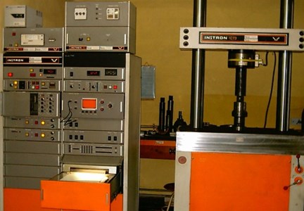
One of the basic issues during projected vibration isolation system is determination of the physico-mechanical properties of one of the basic components of the system which is flexible vibro-isolating element. These studies include i.e. determination of the static and dynamic module Yonge’s, static and dynamic damping factor (in this case the measurement of energy dissipation), aging researches etc. The study of these basic mechanical properties were conducted on static and dynamic testing machine Instron 1273 (Fig. 1) has been classified to class 0.5 of metering devices Class 1 equipped with climatic chamber Instron 3110 which works in the temperature range –60-315 °C ± 1 °C.
Fig. 1Static and dynamic testing machine Instron 1273

The scope of basic research which is to determine the size of selected physical and mechanical properties of materials – the rubber-derived or elastomeric components – for the possibility of their use in vibration isolation systems should include determining the following properties of these materials:
1) Volumetric density at room temperature 20±2 °C,
2) Volumetric porosity ,
3) Shore a hardness at room temperature 20±2 °C and at temperatures –40, –20, 0, 20, 40, 60 °C at speeds of deformation 0,1 mm/s; 1,0 mm/s; 3,0 mm/s,
4) Contractual linear deformation ,
5) Contractual quasi-static and dynamic linear elastic modulus for a range of linear deflection ,
6) Measurement of the damping coefficient ,
7) Quasi-static and dynamic stiffness factor .
Linear dimensions of samples should be determined according to the applicable standards, in this case the Polish norm PN-EN ISO 1923:1999 “Plastics, porous and rubber materials. Determination of linear dimensions”. Transverse dimensions of the test samples of 120 ± 0.5 × 120 ± 0.5 mm was chosen in order to maintain the same size of the sample with an accuracy of ±0.1 mm. Such a large cross-sectional area guarantees the validity of the study elastic element. To eliminate edge effects resulting from perform technology pf elastic plates the test samples were cut at a distance of at least 20 mm from the edge of the plate by water jet and abrasive at high pressure by means of a “water-jet” technology which guarantees the absence of thermal effects of cutting, high quality cutting surface and high repeatability shape and dimensions.
2. Detailed description of research methodology
2.1. Determination of volumetric density
Volumetric density of the material should be determined in accordance with applicable standards in this case with Polish norm PN-EN ISO 845:2000 “Rubber and porous plastic material. Determination of volumetric density” [4] from the relationship:
where: – sample weight, – sample volume.
2.2. Determination of volumetric porosity
Determination of volumetric porosity was carried out in accordance with international standard ISO 865:2005 “Plastics porous. Determination of the percentage volume of open and closed pores in rigid materials” [1, 2]. The volumetric porosity of the material is a measure of the volume fraction of the pores in the material and is calculated from the relationship:
where: – pore volume in the sample.
Due to the particle size rubber granules and a small thickness of the boards surveyed the vast majority of the pore is open. In this case, the specific by testing the open porosity virtually equal to the porosity volume plate. This observation has been used in this study to determine . The test involves the expulsion of air from the open pores and filling them with water. This is achieved by placing the samples in boiling distilled water and then after cooling to define the change the mass of the sample. In view of the above described properties of the panel material:
where: – change of mass of sample after soaking in water, – H2O density.
2.3. Determination of shore A hardness
Determination of Shore A hardness was performed according to standard DIN EN ISO 868: 2005 “Plastics and hard rubber. Determination of hardness by pressing method using a durometer (Shore hardness)”. Hardness Shore A has been determined by carrying out at least 30 measurements of hardness for each sample with a durometer Shore Sauter HBA 100-0 scale A. Tests were performed at 20±2°C. On the basis of the individual results calculated the size of the arithmetic average hardness and its standard deviation the following formulas:
where: – individual result of measurement of hardness Shore A, – number of measurements (30).
Because of the large surface roughness, the porosity of the slabs and large pore size of the indenter relative to the measurements do not reflect the hardness of the plate on a macroscopic scale, but only the hardness of webs of the glued rubber granules used to perform a specific disc. Available on the market hardness for rubber and elastomeric materials allow for spot measurements and do not provide authoritative study feasibility of porous materials. On the basis of the average bridges of rubber and porosity volume board, the weighted average hardness . It is described as follows dependency and a reliable indicator of the hardness of the porous plate in terms of macroscopic:
where: – porosity by volume of the plate material vibration isolating.
2.4. Determination of the mechanical properties of vibration isolation plates based on the stabilized chart of hysteresis loop mechanical work
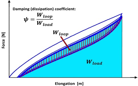
The modulus of elasticity (Young’s modulus) is calculated from secant of stabilized hysteresis loop mechanical work based on relation . In practice Young’s modulus can be calculated from equation where is the angle of inclination secant with respect to the horizontal axis of deformation coordinate system stress and strain . The above definition refers to the case of linear-elastic materials, the course of which resembles the hysteresis loop “spindle”, as illustrated in Fig. 2 and are successfully used for materials with low loss, and so a small span between the curves load and relief. In the case of rubber, the spread is large, so the averaged size of the individually relative to the curve progression or digression would be burdened with large errors.
The rubbers and other elastomeric materials exceeding a certain magnitude of deformation is the phenomenon of a non-linear elasticity. The hysteresis loop changes shape to guide individual sellers within the loop becomes impossible, therefore, cannot be set a modulus based on the above cited rule. The load curve of the hysteresis loop reflects the vibro-isolator response to external mechanical force the curve to relieve it reflects the relaxation of the material. For engineering applications of vibration isolating materials more important is knowledge of the load curve. Given the need to define the contractual elastic modulus it is therefore reasonable to base it on course load curve. An important size for evaluating the vibration isolating properties of the materials is their ability damping expressed by diffuse defined as:
where: – the amount of work losses contributed by vibro-isolator due to internal friction and dispersed into the environment as heat. is the difference between work is made in step progression in accordance with the load curve of the hysteresis loop, and the operation of the vibro-isolator dedicated phase in accordance with the decrease of the unloading curve, – work done by the external force F to deform the vibro-isolator by an set point deflection .
Fig. 2The hysteresis loop and damping coefficient of nonlinear-elastic materials

The definition of the physical work is expressed by the relation:
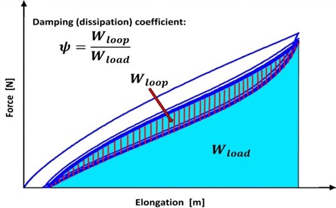
The coordinate system force – deflection , corresponds to the size of the area under the load curve of the hysteresis loop and is the difference between the size of the area under the curve of the load and the size of the area under the curve relief as illustrated in Fig. 3.
Fig. 3A measure of vibro-isolator damping

2.5. Determination of contractual linear deformation
Contractual linear deformation is the maximum relative deformation rubber load curve in a compression test area corresponding to the linear elasticity of rubber in the scope of applicability of Hooke’s law. Contractual linear deformation size can calculated from the equation:
where: – change of the height of the sample during the compression test in area of linear elasticity stable hysteresis loop, – initial thickness of the sample.
2.6. Determination of contractual quasi-static and dynamic linear elastic modulus for a range of linear deflection
Contractual modulus of elasticity of rubber for a range of linear deflection is determined based on the size of the straight section of the load curve stable hysteresis loop compression mechanical work, corresponding to the area studied linear elasticity of rubber in the scope of applicability of Hooke’s law. value can be determined based on the data from the chart stabilized hysteresis loop based on the following equation:
where: – change of the value of force on the load curve hysteresis loop during compression corresponding to the region of linear elasticity, – output cross-section of the sample.
2.7. Determination of measurement of the damping coefficient
The damping coefficient – also known as diffuse – is a dimensionless measure of the size of mechanical work loss due to internal friction in the body elastic and in accordance with Section 2.4 and Fig. 3 can be calculated with the relation:
In order to determine value of damping coefficient first the hysteresis loop chart has been digitized. Then the value of the area within the hysteresis loop corresponding to a stable work and area under the curve corresponding to the work load were calculated and based on these values the value was calculated.
2.8. Determination of quasi-static and dynamic stiffness factor
Volume stiffness coefficient is defined as a derivative of the force inducing strain relative to deformation. In practice it is a measure of the force increment acting on the elastic body under the influence of the individual absolute strain :
Dynamic stiffness factor is determined, directly from the graph of the hysteresis loop in the coordinate system of the force and the absolute deformation , while the modulus of elasticity is determined from the same graph of hysteresis, but in a coordinate system stress and the strain . The coefficient depends on the geometrical dimensions of the test object and whenever they change requires the calculation of new values of . Thus, in contrast to the Young’s modulus stiffness ratio is not a material constant.
3. Conclusion
Technical requirements for the determination of the characteristics of vibration isolating material has not been standardized in Europe and Poland yet. Comprehensively and unequivocally studies of mechanical properties of elastic materials based on the graph of the hysteresis loop of mechanical work have not been normalized also. Manufacturers of rubber-derived materials, research laboratories and certification institutes make the researches of elastic materials according to their own needs and the convenience using different sets of PN and PN-EN ISO, DIN, ASTM and others standards, which hinders the ability to compare each other vibration isolating materials offered. Described in the paper methodology for determination of physical and mechanical properties of vibration isolating materials based on the chart stabilized hysteresis loops based mechanical work is therefore not based on fragmented standards, but on knowledge in the field of mechanics of non-linear elastic materials.
References
-
Targosz Jan Vibration isolation systems in railway and automotive transportation applications. AGH UWND, Krakow, 2007, (in Polish).
-
Osiński Zbigniew Damping of Vibrations. Brookfield, Rotterdam, 1998.
-
PN-EN ISO 1923:1999. Porous Plastics and Rubber. Determination of Linear Dimensions, 1999.
-
PN-EN ISO 845:2000. Rubber and Plastics Porous. Determination of Bulk Density (Volume), 2000.
-
PN-EN ISO 865:2005. Plastics and Ebonity. Determination of Hardness Pressing Using a Durometer (Shore Hardness), 2005.
-
PN-EN ISO 3383:1994. Rubber. General Guidelines for Obtaining Higher Or Lower Temperatures for Research Purposes, 1994.
