Abstract
Biofuel production from algae oil is one of the most attractive process technologies. Few principles of algae cell disruption are presented on the market and introduced on the conference. Mainly, mechanical, thermal and ultra-sonication technologies are widely used in biofuel production. In this paper, authors propose a novel method for algae cell disruption – electrohydraulic shock in the water (Yutkin effect). The short-term plasma can be determined as an effective method for algae cell wall disruption. The experimental results using the proposed method as well as the biological test performed using Scenedesmus algae specie are presented
1. Introduction
Discharge in liquid was studied in the eighteenth century by Lane and Priestley and in the twentieth century by Svedberg and others, who determined that electrical breakdown in liquids and air is associated with a spark as a narrow luminous channel. However, they did not notice that a discharge in liquid represents a new method of converting electrical energy to mechanical energy.
This seemingly primitive principle contains the basic components of modern energy-discharge system: 1) energy-storage capacitor, 2) discharge electrode, 3) spark-gap, 4) force-transfer liquid, and 5) a tank. The technique was refined by the Russian scientist L. A. Yutkin and demonstrated, in 1938, as an industrial tool for metal forming. In 1948, the German physicist F. Frungel [1], after his evaluation of the low mechanical efficiency of an electric discharge in fluid, came to the conclusion that its application was unpromising. Despite this fact, L. A. Yutkin proposed in 1950 to use the electric discharges in fluids in some technological processes, particularly the method on how to create high and ultra-high pressures was discovered [2] and many devices were invented. The licenses for a number of them were sold to Great Britain, Hungary, Germany, Spain, USA, Japan and other countries. Moreover, on the basis of this effect was discovered a whole new trend in the use of discharge phenomena - Impulse-Discharge Technology (IDT) [3].
The necessary high voltage DC power supply more than 20 kV, charges a capacitor storage bank rated from 0,01 to 10 µF. When the electronic trigger circuit is activated energy is rapidly damped into spark-gap electrodes in the water-filled tank. The sudden release of stored energy results in the generation of a vapor bubbles clusters, which acquires the characteristics of plasma. Life-time of plasma is less than 5-10 µs, depending on capacitance value. The instantaneous temperature can be as high as 30,000 °C and pressure estimated to peak out at 10,000 atm and higher.
2. Experimental investigation
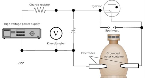
All components are high voltage, needed to pay more attention to safety and to the life-time of spark-gap and electrodes. Proposed electrohydraulic system for algae cell wall disruption schematic is shown on Fig. 1. The high voltage power supply is a fly-back DC/DC converter which takes AC power at 220 V and 1,5 A, and converts it to DC power at 26,000 V and 10 mA. The one 0,01 µF capacitors is used in presented system. The charge resistor has a resistance of 10 Ω. The air gap switch, labeled Spark-gap in Fig. 1, consists of two 1.5 cm diameter ball type steel electrodes, separated by an adjustable gap. However, using ignitron as electronic trigger instead of spark-gap is preferably for this scheme. The water gap, between two electrodes, consists of two 1 mm diameter copper electrodes coated with tin, separated for 2,5 cm gap. The voltage meter, labeled “V” in Fig. 1, reads the potential across the capacitor bank, stepped down by a factor of 100 through the use of an attenuating probe with input impedance about 1 TΩ. Kilo-voltmeter designed and built in our lab consists of 1 TΩ 50 kV and 10 MΩ 1 kV resistors as passive divider and optical high-input impedance voltmeter (up to 600 V with input impedance more than 100 TΩ).
Fig. 1Electrohydraulic system
The stability and energy explosion of spark depends on electrode condition and geometry. Thickness of the electrode, material and insulation properties are very important. The electrodes have a special design to prevent the occurrence of parasitic streamers [4], as shown in Fig. 2. Such geometry needed to protect the electrodes from dielectric breakdown and isolator damages. Copper electrodes are tin plated.
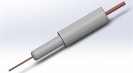
Fig. 2. Design of electrodes
2.1. Spark-gap
Water gap can be modeled as a high-valued resistor in parallel with a small capacitor [5]. The resistance is inversely related to the conductivity k (S/cm) of the water, according to the following relation:
where l is the gap length (cm) and A is the surface area of the electrode face (cm2). The capacitance of the water gap is related to the dielectric constant K of the water as follows:
where ε0 is the permittivity of free space. The dielectric constant of tap water is roughly 50, which means that the capacitance is about 0,0018 nF. The conductivity of tap water is typically between 100 and 200 µS/cm [6], so the resistance of the water gap is about 1,67 MΩ.
To be precise, Eqs. (1) and (2) can also be applied to the air gap, but the capacitance is several orders of magnitude lower comparing with water gap, and the resistance is so high that it can be considered infinite. Thus, at least initially, the air gap acts as a break in the circuit.
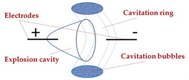
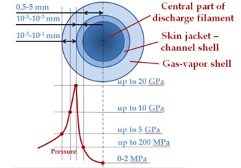
Fig. 3a) Cavitation phenomenon during electrohydraulic shock, and b) spark channel structure and pressure distribution
a)
b)
When the electronic trigger circuit is activated, energy rapidly damped into spark-gap electrodes submerged in the water-filled tank. The cavitation phenomenon of electrohydraulic shock and pressure distribution in lightning channel are presented in Fig. 3. The cavitation tor (cavitation ring) includes many rounds and stretched bubbles. The explosion effects strongly depends on capacitor value and apply voltage, we can vary electrohydraulic shock wave from “soft” to “hard” [4].
As current begins to flow in the air gap, the gas is ionized by the electrons to the point where it becomes a plasma. Plasma is a dynamic, highly conductive, subatomic state of matter, consisting of ions, free electrons, and radicals.
The plasma channel between the electrodes expands as the current increases, reaching very high local temperatures and pressures, and giving off visible and UV light. Electrons flow toward the anode, and cations flow toward the cathode. The cathode surface is damaged over time by the impacting cations. The anode is not damaged as much by the electrons, since they are much lighter and have less kinetic energy than the cations [7].
Once the water gap begins firing, the resistance drops, and the voltage across it falls to about 150 V, just like in air gap. The capacitors discharge according to the equation [8]:
where U0 is the initial capacitor voltage, and R is actually closer to 0,5 ohms, due to the additional resistance of the 1 m of diam. 1 mm wire running from the capacitor unit to the submersible unit and back. The time constant of the discharge is about 5 ns.
Once both gaps (air and water) are firing and the capacitors begins to discharges, the current will be uniform with respect to position throughout the discharge circuit, and it will vary with respect to time according to the equation [8]:
where U0/R is the maximum current through the circuit, calculated to be about 52 kA.
Before discharge, the capacitor stores energy according to the equation:
which corresponds to a maximum stored energy of 3,38 J, which is released in each capacitor discharge. This energy is dissipated in the plasma channel during the discharge.
2.2. Experimental results
Prototype of the electrohydraulic shock was established for experimental investigation as shown in Fig. 4. The capacitor discharges 10 times (dissipated energy is about 33,8 J) through the algae cells water mixture, during approx. 1,2 seconds in electrohydraulic shock reactor as shown in Fig. 4. Fig. 4(a) represent the experimental setup before discharge and very bright glow represent the underwater discharge on the right.
Fig. 4Experimental electrohydraulic shock test stand
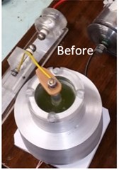
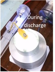
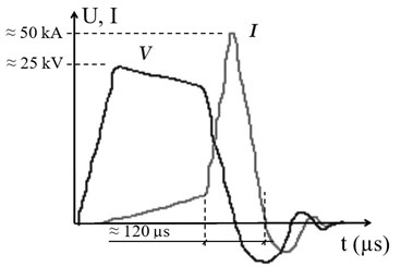
Tektronix TDS-3012 digital phosphor two channels oscilloscope used for voltage (1 channel) and current (2 channel) traces visualization running in one shot mode with internal synchronization by voltage channel. The passive divider of high-voltage measurement included 1 TΩ 50 kV and 100 kΩ 1 kV resistors (division ratio is 10000) and active follower with input impedance about 1,5 TΩ using BiMOS Operational Amplifier CA3140A. A Rogowski coil based electrical device for measuring high speed current pulses was created in our lab. Since the voltage that is induced in the coil is proportional to the rate of change (derivative) of current in the straight conductor, the output of the Rogowski coil is connected to an electronic integrator circuit based on OPM to provide an output signal that is proportional to the current. Voltage and current oscilloscope tracing in spark gap between electrodes in water are shown in Fig. 5.
Fig. 5Voltage and current curves in underwater spark gap
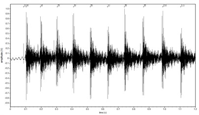
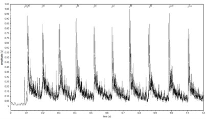
Avisoft bioacoustics UltraSoundGate 116H with charge amplifier and adjustable hi-pass filter were used for underwater acoustical sound analysis. Pulse train measurement results use RESON, TC-4013-1 type hydrophone are shown in Fig. 6 both original signal (Fig. 6(a)) and after pulse train analysis based on rectification plus exponential decay envelope (Fig. 6(b)).
Fig. 6Pulse train measurement by hydrophone: a) original signal; b) after pulse train analysis (rectification plus exponential decay)
a)
b)
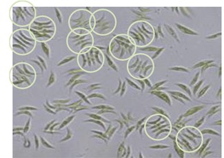
To determine the shock effect on colonial (coenobial) algal cultures the green algae “Scenedesmus acutus” Meyen (strain 2012-KM (1)-B3) (Fig. 7(a)) of 4 (or 2, 8, 16) cells attached side by side, arranged linearly or zigzag; cell body elliptical or spindle or crescent in shape; terminal cells with spiny projections in many species; cell wall usually smooth, but in some species granulated or dented or ridged were employed.
Species was established through the isolation of a single colony from a water sample of Curonian Lagoon, Lithuania. The culture was grown in modified Wright’s medium (MWC) [9] and maintained at 18-20 °C, in photoperiod of white fluorescent light ~100 µmolm-2s-1 on a 12:12 light:dark photo-cycle.
Algal cells in control and processed culture samples were calculated in Nageotte counting chamber (volume 0,05 cm3) immediately after processing. Each experiment counting was repeated at least three times. The changes in “Scenedesmus acutus” abundance were expressed for each single cell and for two three and four cells colonies.
Although “Scenedesmus” is capable of producing many kinds of bio-fuels such as bio-hydrogen, biodiesel, bioethanol and drop-in fuels, most extensive research has been done on the use of “Scenedesmus” for bio-diesel production. Like all algae systems, the implementation of integrated biofuel production of “Scenedesmus” from the laboratory findings has challenges in large-scale production. Major challenges include nutrient supply and recycling, gas transfer and exchange, PAR (Photosynthetically Active Radiation) delivery, cultural integrity, environmental control, land and water availability, harvesting, and genetic and metabolic engineering.
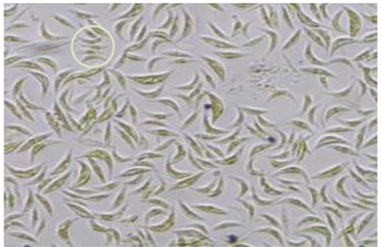
Fig. 7“Scenedesmus acutus” colonies: a) control, b) after the shocks. Scale bar indicates 10 µm
a)
b)
“Scenedesmus acutus” algal cells culture control sample is shown in Fig. 7(a). Four cell colonies are indicated in circles, two and three cell colonies are visible as well. The changes after electrohydraulic shock is shown in Fig. 7(b). Most of four, three or two cells colonies are broken, the photo in Fig. 7(b) illustrate scattered single algae cells. The black particles in Fig. 7(b) are the metal colloids.
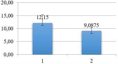
In Fig. 8 column 1 is presented the inspection lot of algae cells (mln/ml) and column 2 illustrates of algae cell specie numbers after 10 discharged of capacitance (during 1,2 seconds). It is necessary to underline, that results given by dissipated energy in underwater spark-gap about 33,8 J.
Fig. 81 – inspection number of algae cell specie (mln/ml), 2 – after 10 discharges
3. Conclusions
Electrohydraulic shock widely used in the last century for metal forming, in marine electro hydraulics and for treating polluted water sources, etc. In this paper, authors suggested using the electrohydraulic shock as new method for algae cell disruption. Nowadays, the algae cell decomposition is widely used in the cosmetics and fuel industry. Actually, all algae cell components can be used in a practical manner. The main advantage of this method, from our point of view, significant energy consumption reduction comparing with other methods and as a consequence, increase the efficiency, unattainable by other technologies. The energy consumption of 10 capacitance’s discharges (0,01 µF) in our experiments, measured by Tunex power meter was less than 0,2 Wh. In spite of this fact, electrohydraulic shock during 1,2 seconds only, destroy majority numbers of “Scenedesmus” colonies and some number of algae cell species as shown on Fig. 7(b) and Fig. 8 after inspection.
After experimental investigation we can assume than the electrohydraulic shock is recognized as an effective method for algae cell disruption. Practical application of this method can be applied at a higher voltage (up to 50 kV) and capacitance at least 0,1 µF.
Additional biological test needed to estimated quantity of protein or other components after electrohydraulic shock.
References
-
Frungel F. Impulse Technique. Generating and Applying of Capacitor Discharges. Energiya Publishing House, 1965, p. 488.
-
Yutkin D. A., Goltsova A. I. Methods for Creating High and Super High Pressures. A.s. USSR 105011, 1950.
-
Eremin V. Y., Budanov A. A. The deformability of sand soils by manufacturing of piles with the help of impulse-discharge technology (IDT). Science and Technology Journal “Vestnik MGSU”, Vol. 1, 2006, p. 150-164.
-
Yutkin L. A. Elektrogidravlicheskii effekt i ego primenenie v promyshlennosti (The Electrohydraulic Effect and Its Use in Industry). Mashinostroenie, Leningrad, 1986.
-
Hickman B. Personal Communication. Atlanta, GA, 2004.
-
The Story of Conductivity. Horiba, Ltd., http://global.horiba.com/story_e/conductivity /conductivity_05.htm, 2004.
-
LaPointe R. E. Pseudospark Switches. http://users.tm.net/lapointe/Pseudospark_Switches.html, 2004.
-
Salomsom E. B. Charging and discharging a capacitor through a resistor. 3rd Samahang Pisika ng Visayas at Mindanao National Physics Conference Workshop, Ateneo de Zamboanga University, Zamboanga City, Philippines, 2001.
-
Guillard R. R. R., Lorenzen C. J. Yellow-green algae with chlorophyllide. Journal of Phycology, Vol. 8, 1972, p. 10-24.
Cited by
About this article
This research is carried out using funds from Research Council of Lithuania Project Nr. MIP-018/2014.
Sergejus Borodinas – the idea and theoretical background, experimental setup, electrical circuit assembly. Piotr Vasiljev – the idea and design of the proposed system, theoretical background and general supervising. Regimantas Bareikis – system manufacturing, assembly, and technical adjustments. Arunas Struckas – acoustic and electric measurements. Jurate Kasperovicienė – algae cultivation, post experimental algae destruction rate calculations.

