Abstract
This article deals with the problem of transfer of ultrasonic vibrations on flexible hub-waveguide system and is a continuation of research in this field [1-3]. The main field of application of flexible hub-waveguides-minimally invasive surgery for treatment of vascular diseases, where they are used to restore patency of blood vessels by destroying blood clots and tromboèmbolov. Thanks to the possibility of elastic deformation of flexible hub-waveguides, they can be delivered through a catheter system to the most remote places of the blood vessels, producing ultrasonic processing of affected sites with minimal surgical intervention. It should be borne in mind that during the work of the PA system can change its own hub-frequency waveguides and frequency generator, and this can lead to beating frequencies, formation of flexural vibrations of a working part, etc. This article therefore tasked to define the conditions of formation of low-frequency oscillations of a bend when passing ultrasonic vibrations of flexible waveguide system.
1. Formulation of the problem
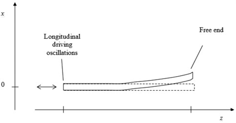
A rod, one end of which is free, and the other is oscillating in the axial direction with predefined frequency and amplitude, is considered (Fig. 1). It is required to investigate conditions for the flexural oscillations appearance.
Fig. 1The axial direction with predefined frequency and amplitude
2. Transformation of the longitudinal vibrations to the flexural ones
2.1. Parameterization of the state
Function x(t,z), which define a shape of the rod at the instant of time t, should be determined by means of the elasticity theory equations solving (t – time, z – longitudinal coordinate, x(t,z) – transverse deflection of the rod points). One of the commonly used numerical methods of the solution consists in the piecewise-constant or piecewise-linear approximation of x(t,z), that leads to the corresponding finite-difference computational scheme. Nevertheless, in practice, this approach proved to be ineffective when applied to the problem considered, because it requires the use of very dense computational grids to achieve the appropriate accuracy (to recover the effect of interest) that makes the computational time to become too expensive.
It has been appear to be more efficient the approach based on the Fourier expansion of x(z), the coefficients of which as functions of time being considered as generalized coordinates representing the state of the system. Taking into account the appropriate boundary conditions [4]:
This expansion reduces to:
2.2. Dynamical equation
After expression of Lagrangian function of the system in terms of the generalized coordinates An(t) and appropriate transformations, we derive a system of equations for An(t) which determine the dynamics of the system. When restricting the Eq. (1) by the first term only, the equation for A(t) takes the form:
where ω20=πhk4/4ρβ, ρ – linear density, k=π/2L, L – length of the rod, β=3π/4-2, h=EI, E – elastic modulus, I=πR4/4, R – radius of the rod, f(t)=Δz(t) – longitudinal displacement of the rod caused by an external source action, that we consider to be a given function of time in this section.
Initial conditions:
The Eq. (2) differs from the conventional equation of forced oscillations in that the given function of time (source function) enters into the equation not as a free term, but as an additional summand in the expression for coefficient at the A (parametric excitation [5]).
2.3. Dependence of the amplitude of flexural oscillations on the frequency of longitudinal oscillations. Low-frequency resonance
The modelling has been performed for:
where ω and a are, respectively, a frequency and an amplitude of the longitudinal vibrations.
a) A case of a= 0 (external excitation is absent);
In this case Eq. (2) takes a form of the free oscillations equation with frequency ω0. For ρV= 7850 kg/m3, E= 204 GPa (steel), R= 0.5 mm, and L= 210 mm, the value of the free flexural oscillation frequency is ν0= 19.5 Hz (ω0=2πν0).
b) A case of A0= 0 (no initial deflection of the rod from the equilibrium position). Then, A≡ 0 and x≡ 0;
c) General case.
The Eq. (2) with function f defined by Eq. (3) has been integrated numerically for various values of the excitation frequency ν (ω=2πν, a= 1 μm, A0= 0.1 μm, the other parameters values – as in a case a). The results are presented in Fig. 2 in a form of dependence of the amplitude of flexural oscillations on the frequency of longitudinal oscillations.
Fig. 2Dependence of the amplitude of flexural oscillations on the frequency of longitudinal oscillations
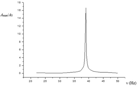
A specific feature of this amplitude-frequency dependence is a sharp pick at ν=2ν0= 39 Hz, that is in accordance with the parametric resonance theory [5]. For all other frequencies (except that of the near-resonance region) the amplitude of flexural oscillations is negligible. So, the ultrasonic longitudinal vibrations per se can’t be a reason of significant flexural oscillations.
3. Formation of the low-frequency component of the ultrasonic longitudinal vibrations of a rod
The equation of the longitudinal vibrations of a rod is [4, 6]. (In this section we use generally a notation accepted in [6]):
where c – speed of sound. Its solution under initial condition:
and boundary conditions:
(one end of the rod moves by a given law, the other is fixed (L – length of the rod)) is [6]:
where:
If the second end of the rod is free (instead of to be fixed), then the second boundary condition becomes [4]:
The solution of Eq. (4) satisfying the initial condition Eq. (5) and the boundary conditions Eqs. (6a) and (8) is a function:
where ¯μ is determined by the expression Eq. (7).
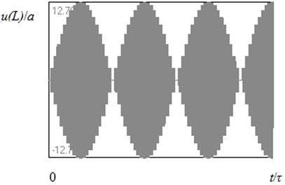
Figs. 3, 4 show the results of calculations of u(L,t)/a in accordance with Eq. (9) when:
Two cases where considered: the first one corresponds to the condition of resonance (Fig. 3), and the second one is for the case with a mismatch of the frequencies (Fig. 4). One can see that, in the first case, the unlimited growth of the amplitude of the oscillations takes place (losses were not taken into account). In the second case, a beating regime of oscillations is established with the frequency of beats Ω being equal to the difference between the frequency of source and the resonant frequency. In this case the signal is a periodical function of time with fundamental frequency Ω.
Tables, figures and equations are placed after the paragraph in which they are first referenced. References should look as follows: Fig. 1, Fig. 1-2, Fig. 1(a), Table 1, Eq. (1), Eq. (2)-(3).
Fig. 3Time history diagram of the longitudinal displacement of the free end of the rod; L/λ= 2.25 (a length of the rod corresponds to the condition of resonance; λ – wavelength, τ – period of oscillations)
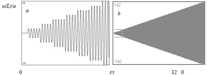
Fig. 4The same, as in Fig. 3, for L/λ= 2.275 (when the length of the rod is 1.1 % greater than the resonant value of it)
So, under appropriate conditions, as a result of multiple reflection of longitudinal waves by the ends of the rod, oscillations with low frequency Ω≪ω are presented in the spectrum of the rod vibrations, that can be a reason of the flexural oscillations.
4. Conclusion
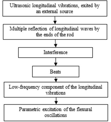
To summarize, the mechanism of transformation of ultrasonic longitudinal vibrations of a rod to the low-frequency flexural oscillations can be presented by the next scheme (Fig. 5).
Fig. 5Mechanism of transformation of ultrasonic longitudinal vibrations of a rod to the low-frequency flexural oscillations
References
-
Minchenya V. T. Analysis of linear oscillations of the two-staged ultrasonic waveguide in thrombolysis healing. Report for Byelorussian Academy of Sciences. Vol. 53, Issue 6, 2009, p. 114-119, (in Russian).
-
Stepanenko D. A. Modeling of flexible waveguides for ultrasonic vibrations transmission: Longitudinal and flexural vibrations of non-deformed waveguide. Ultrasonics, Vol. 50, Issue 3, 2010, p. 424-430.
-
Bubulis A., Minchenya V. T., Stepanenko D. A. Semi-automatic modal analysis of flexible ultrasonic waveguides in ANSYS. Tools Production, 2009, p. 145-146.
-
Landau L. D., Lifshitz E. M. Theory of Elasticity. Pergamon, Oxford, 1981.
-
Landau L. D., Lifshitz E. M. Mechanics. Pergamon Press, Oxford, 1960.
-
Tikhonov A. N., Samarskii A. A. Equations of Mathematical Physics. Dover Publications, NY, 1990.
