Abstract
For investigating the characteristics of the resonance changer and its influence on the longitudinal vibration of marine propulsion shafting system, by the transfer matrix method, the model of the shafting system, including the resonance changer is established. The influences of the resonance changer with various designing parameters on the force transmissibility through the thrust bearing foundation are evaluated. The results show that, the introduction of the resonance changer eliminates the resonance at original 1st natural frequency and introduces another two resonance peaks, as well as significantly lowering the maximum response compared with the original peak. The right one is attributed to the resonance changer, while the other is due to excitation of the other shafting system components. The 2nd natural frequency moves towards the high frequency direction and the peak value nearly stay invariable. If the designing parameters of the resonance changer are well optimized, the objective of reducing the longitudinal vibration transmission through the shafting system to the hull could be achieved.
1. Introduction
For marine vessels, when the blade passing frequency of the propeller is equal or close to the natural frequency of the shaft longitudinal vibration, there will be excessive longitudinal vibration of the shafting system, which is not only the reason of the fatigue damage of the shaft and the wear of the thrust bearings, but also the main source for low frequency shipboard noise and underwater sound radiation from a submarine hull. For reducing the propeller-induced longitudinal vibration, several methods are presented [1-4], i.e. increasing the number of propeller blades, moving the thrust bearing further afterward, and adopting new thrusters such as water jet propulsion device. Such method is difficult to implement and is not always effective. The resonance changer (also called RC) [4] proposed by GOODWIN is a new option in reducing the propeller-induced vibration, and since then it has received much more attentions.
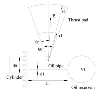
Fig. 1 shows a thrust bearing which is a combination of a fluid-equalized thrust bearing [5] and a RC, and it could help reduce shaft longitudinal vibration. The thrust pads are supported by pistons which are in turn supported by hydraulic fluids. The piston cylinders are all interconnected and the supported fluids are connected to an oil reservoir through an oil pipe. The axial load is carried by the supported fluids and the disturbance forces are transmitted to the oil reservoir through the oscillatory oil pressure in the oil pipe. In this procedure, the virtual stiffness Kh is produced by the compression and expansion of the oil in the reservoir, and the virtual mass Mh and virtual damping Ch are produced by the viscous oil flow in the oil pipe. So, the piston cylinders, the supported fluids, the oil pipe as well as the oil reservoir work together as a RC. A replenishment hydraulic fluid system is also provided to compensate for shaft movement due to fluid leakage and the compression or expansion of the oil in the reservoir. Fig. 2 shows the main designing parameters of a thrust bearing with a RC, including r1, r2, θ, rp, θp, m, V1, d0, L1, d1, which represent the inner radius of pad, the outer radius of pad, the angular of pad, the radius of supported point, the angular of the supported point, the number of thrust pads and oil cylinders, the volume of the oil reservoir, the diameter of the piston cylinder, the length and diameter of the oil pipe, respectively.
Fig. 1A schematic diagram of a thrust bearing with a RC
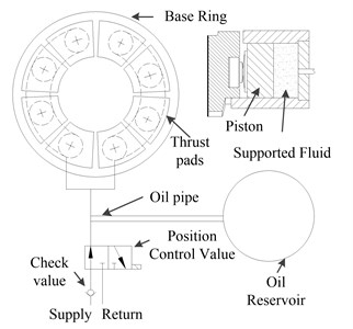
Fig. 2Specifications of a thrust bearing with a RC
2. Model of longitudinal vibration of propulsion shafting system
The main propulsion shafting system of a marine vessel can be simplified into the key features shown in Fig. 3 as far as the axial vibration is concerned, where Uli, Fli, Uri, Fri represent the amplitude of displacement and force of component i, and superscripts ‘r’ and ‘l’ denote the right end and the left end of component i. Subscript ‘i’ denotes different component. In detail, ‘1’,‘2’,‘3’,‘4’,‘5’ denote the propeller, the stern shaft, the thrust bearing, the intermediate shaft and the coupling, respectively, and ‘t’, ‘h, ‘b’ denote the thrust collar, the RC, the foundation, respectively. Ti represents the transfer matrix of component i.
Fig. 3A model of longitudinal vibration of propulsion shafting system

2.1. Model of the thrust bearing with a resonance changer
The simplified model of the RC is shown in Fig. 3. As described in literature [4], a mathematical analysis can be made as followings:
where, A0=mπ(d20/2)2 is the total cross-sectional area of the supported fluids, A1=π(d21/2)2 is the cross-sectional area of the oil pipe, and P, ρ1, μ1, B1 are the oil pressure in the piston cylinder, the density of the oil, the oil viscous and the bulk modulus of the oil, respectively. Then, Mh, Kh, Ch, and Fh can be given by Eq. (2). Fh is the natural frequency of the RC. The transmission matrix of the RC is respectively expressed as Eq. (3), in which ω is the angular frequency of the disturbance forces:
The transmission matrix of the thrust bearing with a RC and its foundation is shown as:
where, Kb, Mb are the stiffness and mass of the thrust bearing foundation(including the supporting and surrounding structures), and Ko, Co are the axial stiffness and damping of the lubricated oil film. The procedure of calculating the dynamic coefficients described in literature [6], which is based on the thermal hydrodynamic lubrication theory and the perturbation equations formulated from a first order Taylor expansion of the oil film and pressure, is adopted in this paper. The hull of the ship or submarine could be regard as a rigid boundary condition, which means Urt=0. Then, Eq. (4) can be deduced as:
=(Kb-Mbω2)(Ko+jωCo)(-Mhω2+Kh+jωCh)(Kb-Mzω2+Ko+jωCo)(-Mhω2+Kh+jωCh)+(Kb-Mzω2)(Ko+jωCo)Utr,
where Ke represents the equivalent stiffness. Mth is the mass of the thrust collar. Then, the transfer matrix of the thrust bearing with a RC and the foundation can be expressed as:
2.2. Model of longitudinal shaft vibration and responds calculation
The transfer matrix of the shafting system T is shown as Eq. (7), in which, T11, T12, T21, T22 are the elements of T. The transfer matrices of the propeller and the coupling are expressed as Eq. (5) and the transfer matrix of the uniform shaft undergoing longitudinal vibration is expressed as Eq. (6).Where, Mp, Mc, l, E, ρs, A are the lumped mass of propeller, the lumped mass of coupling, the length of shaft, Young’s modulus, the density of the shaft, the cross-sectional area of the shaft, respectively:
When the load f0 is acted on the propeller, the relationship between state vectors of the right and left ends of the shafting system is presented in Eq. (10). Substituting the free-free boundary conditions (F1l=F5r=0) into Eq. (10), the state vector of the propeller end can be obtained by solving the Eq. (10), shown as Eq. (11). Utilizing the state vector of the propeller end and the accumulated transmission matrix from propeller to the component i, the response at any component along the shaft could be obtained:
The force transmissibility through the thrust bearing foundation could be easily obtained by Fbr/f0.
3. Discussions of results
The corresponding configuration data of the thrust bearing are load F= 200 kN, shaft speed n= 220 r/min, r2=0.24 m, r1=0.125 m, m= 8, θ0=0.611 rad, rp=0.186 m, θp=0.3543 rad. The corresponding configuration data of the shaft are l1=14 m, l2=2 m, the diameter of the shaft d=0.16 m, Mp=7000 kg, Mc=1000 kg, ρs=760 kg/m3, E=200 GPa. The corresponding configuration data of the RC are d0=60 mm, d1=5 mm, V1=1.6 L, L1=2 m, ρ1=760 kg/m3, B1=1940 MPa, μ1=0.23 pa·s.
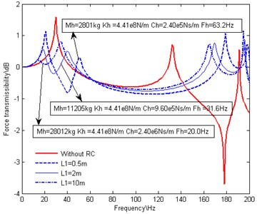
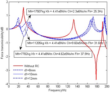
Fig. 4 is the contrast figure of the force transmissibility through the thrust bearing foundation before and after a RC is attached to the thrust bearing. Fig. 4(a), Fig. 4(b), Fig. 4(c) and Fig. 4(d) exhibit the influences of the volume of the oil reservoir V1, the diameter of the piston cylinder d0, the length L1 and diameter d1 of the oil pipe, respectively.
Compared with the situation in absence of the RC, the introduction of the RC results in the elimination of the dominant peak at the original 1st natural frequency and alteration of the 2nd natural frequency much more towards the high frequency direction. Simultaneously, it also introduces another two dominant resonance peaks around the original 1st natural frequency. The amplitudes and locations of the two peaks are related to the different parameters of RC, but both of the amplitudes are lower than the original one. Off resonance frequency, there is little difference between the situations with and without a RC, which proves that the RC only exhibits good performance over a narrow frequency bandwidth.
As shown in Fig. 4(a), with the increasing of V1, Kh and Fh decrease while Mh, Ch stays invariable. The peak on the right side moves towards the original 1st natural frequency and the amplitude of the peak increases. As shown in Fig. 4(b), with the increasing of d0, Mh, Kh and Ch decrease while Fh stays invariable. The two peaks move together towards the original 1st natural frequency and the amplitudes of the two peaks stay nearly equal and decrease gradually. As shown in Fig. 4(c), with the increasing of L1, Mh and Ch increase and Fh decreases while Kh stays invariable. The peak on the right side moves towards the original 1st natural frequency and the amplitude of the peak increases. As shown in Fig. 4(d), with the increasing of d1, Mh and Ch decrease and Fh increases while Kh stays invariable. The peak on the right side moves towards the high frequency direction and the amplitude of the peak decreases.
From above analysis, it is obvious that the peak on the right side is attributed to the RC, while the peak on the left side is due to excitation of the original shafting system. It could be concluded that, with the decreasing of Fh (increasing of Mh or decreasing of Kh), the influences of the RC on the longitudinal vibration of the shafting system is more and more significant. And that is why the two peaks moves and changes synchronously when Fh stays invariable. It could be foreseen that, when V1 is small enough, Kh will be infinite, so the RC could be regarded as a rigid support. As a result, the peak on the left side overlaps the original peak at 1st natural frequency, while the peak on the right side disappeared. When L1 is long enough or d1 is small enough, Mh will be infinite. As a result, the peak on the right side will overlap the original peak at 1st natural frequency, while the peak on the left side disappeared. Be careful, because of the limitation of the axial shaft movement, Kh should not be too small.
Considering the mass, stiffness and the 1st natural frequency of the shafting systems, optimizing V1, d0, L1, d1 to acquire a natural frequency of the RC which is close to the original 1st natural frequency of the shafting system, a appropriately large virtual mass, a appropriately small virtual stiffness and a appropriate virtual damping, there will be a good effect of vibration reduction when the RC is attached to the shafting system.
Fig. 4Effect of RC with variations in designing parameters on force transmissibility
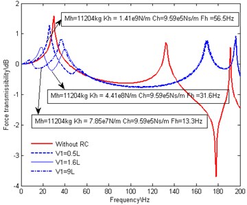
a) Variations in the volume of the oil reservoir
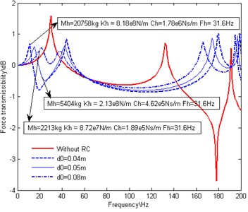
b) Variations in the diameter of the piston cylinder
c) Variations in the length of the oil pipe
d) Variations in the diameter of the oil pipe
4. Conclusions
In this paper, force transmissibility through the thrust bearing foundation for different cases is employed to study the dynamic behavior of the RC as well as its influences on the longitudinal vibration of the propulsion shafting system. The conclusions can be summarized as follows:
The introduction of the RC eliminates the resonance at low frequency suffered previously and introduces another two resonance peaks around original 1st natural frequency, as well as significantly lowering the maximum response compared with the original peak. The peak on the right side is attributed to the RC, while the other is due to excitation of the other shafting system components. Furthermore the resonance frequency of the 2nd natural frequency moves towards the high frequency direction and the peak value nearly stay invariable. Such variations in force transmissibility characteristics are linked with the variation of the designing parameters of the RC, such as the diameter of the piston cylinder, the diameter of the oil pipe, the length of the oil pipe, the volume of the oil reservoir. By optimizing above parameters, the purpose of reducing severe longitudinal vibration and its transmission into the hull through a thrust bearing over a specified frequency range would be realized.
References
-
Zhang G. B., Zhao Y., Li T. Y. Propeller excitation of longitudinal vibration characteristics of marine propulsion shafting system. Shock and Vibration, 2014, p. 1-19.
-
Pan J., Farag N., Lin T., Juniper R. Propeller induced structural vibration through the thrust bearing. Proceedings of Acoustics, Australia, 2002, p. 390-399.
-
Dylejkoa P. G., Kessissogloua N. J., Tsob Y., Norwoodb C. J. Optimization of a resonance changer to minimize the vibration transmission in marine vessels. Journal of Sound and Vibration, Vol. 300, Issues 1-2, 2007, p. 101-116.
-
Goodwin A. J. H. The design of a resonance changer to overcome excessive axial vibration of propeller shafting. Transactions of Institute of Marine Engineers, Vol. 72, 1960, p. 37-63.
-
Shapiro W., Graham R., Anderson G. Predicted performance characteristics of hybrid fluid-equalized tilting-pad thrust bearings. Journal of Lubrication Technology, Vol. 105, 1983, p. 476-483.
-
Jang G. H., Kim Y. J. Calculation of dynamic coefficients in a hydrodynamic bearing considering five degrees of freedom. Journal of Tribology, Vol. 121, 1999, p. 499-505.
