Abstract
The present study concerns with dynamic characterization and optimal design of a partially treated magneto-rheological (MR) sandwich plate. An aluminum sandwich plate, partially treated with MR fluid (MRF 132DG) was fabricated for dynamic characterization in the laboratory. The MR-filled cavity in the plate was subjected to a uniform magnetic flux using two permanent magnets located at top and bottom of the structure. The dynamic response characteristics of the sandwich plate were experimentally obtained under harmonic force excitations. A finite element model of the partially-treated MR sandwich plate was developed using classical plate theory considering the effect of slippage between the top and bottom layers. The validity of the finite element model was demonstrated by comparing the theoretical results with those of the experiment. An optimization problem was subsequently formulated and solved using genetic algorithm (GA) to identify optimal locations for the MR fluid treatments for realizing maximum variations in stiffness and damping properties of the structure corresponding to the lower three modes of flexural vibration, individually and simultaneously, in response to the applied magnetic field. The effect of shear deformation on the vibration properties of the partially treated sandwich plate was particularly highlighted. The results suggest that the MR fluid treatments can significantly alter the stiffness and damping properties of the sandwich structure under noticeable shear strain, while a partial treatment could yield the changes in stiffness and damping comparable to those of a fully-treated plate.
1. Introduction
Magnetorheological (MR) fluids, owing to their varying and reversible properties in response to applied magnetic flux, could be employed as semi-active constrained layer damping in sandwich structures. It has been shown that structures with total MR-fluid treatments exhibit substantial changes in their stiffness and damping properties when subjected to external magnetic field. The total treatment of the structure, however, contributes to increased structure weight and cost, and may impose challenges with regard to practical implementations [1]. Structures with only partial treatments of MR-fluids, on the other hand, may also yield desired levels of variations in both the stiffness and damping properties, while facilitating the design and implementations. The identification of optimal locations of localized MR-fluid treatments in a structure to achieve desired controllability, however, continues to be a significant design challenge.
The dynamic characteristics of simple beam structures treated with either magneto- or electro-rheological (ER) fluids have been widely investigated via analytical and experimental methods [2]. Only a few studies, however, have attempted such properties of plate structures treated with ER or MR-fluids. These have shown that partial damping treatments may be more effective in attenuating vibration of the host layer than the full treatment [2]. Oyadiji [3] reported that a partial-treatment yields superior ratio of vibration suppression to consumed energy compared to the full ER-fluid treatment, which was further supported by Cho et al. [4] through study of vibration responses of a fully- and partially-treated ER fluid plate. Mohammadi and Sedaghati [5] proposed an optimal ER-fluid treatment configuration for a sandwich cylindrical panel to achieve maximum damping corresponding to first two transverse modes. Rajamohan et al. [2] proposed optimal locations of MR-fluid treatments in an adaptive MR-fluid beam structure to achieve highest modal damping factors.
In this study, dynamic characteristics of a partially treated MR-fluid sandwich plate are investigated via experimental and analytical methods. A finite element model based on classical plate theory was developed to formulate governing equations of motion of the partially-treated MR plate. The validity of the model was demonstrated using the measured data. Optimization problems were subsequently formulated and solved to identify optimal treatment locations resulting in highest stiffness and damping variations corresponding to the first three modes.
2. Mathematical formulations
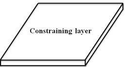
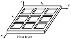
The finite element model of a partially treated multi-layer sandwich plate (length (l1); width (l2)) is formulated considering an isotropic host layer (thickness =h2+h3) with m×n equal cavities of height h2 and a constraining layer of thickness h1, as shown in Fig. 1 (m=n= 3). The MR fluid may be applied to one or more cavities within the core layer to achieve either total-or partial MR-fluid treatments. Two types of plate elements are used for modelling the structure. The type 1 elements, a two-layer plate element comprising bottom and top elastic layers bonded using an adhesive layer, discretizes the walls surrounding the cavities, and constitutes four nodes with ten-DOF per node (longitudinal and transverse displacements, and slopes about x- and y-axis for the top and bottom layers). It is assumed that the adhesive layer cannot provide perfect bonding between the face layers, and thereby the effect of slippage between the layers is incorporated, considering longitudinal displacement discontinuity between the top and bottom layers in the interface. The compatibility condition is used to formulate the slippage in the following form:
τyz=k*(v(1)(x,y,-h1/2,t)-v(2)(x,y,h2+h3/2,t)),
where τ is the transverse shear stress, and u and v are displacements along x and y directions, respectively. Superscripts (1) and (2) refer to the top and bottom layers, respectively. k* is complex shear stiffness parameter of the adhesive layer. The transverse and longitudinal displacements of the element can be expressed in terms of nodal displacement vector.
Fig. 1Schematic of the multi-layer plate with partial MR fluid treatment

The type 2 element used is a sandwich plate element with two elastic face layers and a MR fluid layer. The element comprises four nodes with ten-DOF per node (longitudinal and transverse displacements, and slopes about x- and y-axis for the elastic layers). The transverse shear deformation and rotary inertia are neglected considering very low thickness to length ratio of face layers. Slippage between layers is neglected to achieve continuous displacement profile through the thickness It should be noted that MR fluid layer behaves visco-elastically in the pre-yield region, where the shear stress is related to shear strain by complex shear modulus G*:
where G' is storage modulus and G'' is the loss modulus.
The kinetic and potential energy of the elements are formulated and Lagrange’s method is used to derive governing equations of motion of the elements [6]. The system governing equations are obtained by assembling the stiffness and mass matrices of the elements discretizing the structure. In order to formulate the system mass and stiffness matrices, the compatibility condition, i.e., identical transverse and axial displacements and slopes at interfaces of the two elements, must be satisfied. Although, application of adhesive layer in type 1 elements cannot provide perfect bonding between the top and bottom layers, it ensures more uniform transverse deformations of the walls surrounding the cavities. The Lagrange multipliers technique is employed to apply this constraint in the finite element model. The natural frequencies and loss factors are evaluated through solutions of the following system of equations:
where [M], [K] and [B], are the system mass, stiffness and constraint coefficient matrices, respectively, and [d] and {χ} are the displacement and Lagrange multiplier vectors, respectively.
2.1. Identification of optimal locations of MR fluid treatments
Optimization problems are formulated to seek optimal locations of MR fluid treatments in the plate structure with m×n cavities so as to enhance its vibration control in terms of variations in stiffness and damping corresponding to three lower modes, individually and simultaneously. The optimization problems are formulated considering four different objective functions. The first two problems were defined with objective to maximize variations in stiffness (‘case 1’ and ‘case 2’), evaluated in terms of increase in first three natural frequencies, individually and simultaneously, when the applied magnetic field is varied from 0 to 90 mT:
where and are objective functions, is weighting and is natural frequency corresponding to mode at a specific magnetic flux density . The design vector , defines the locations of treated cavities () and is the maximum number of fluid-filled cavities. Subsequent optimization problems, ‘case 3’ and ‘case 4’, are formulated with an objective to maximize loss factor corresponding to first three vibration modes 90 mT:
where is the weighting factor, and the loss factor corresponding to mode is determined from the real () and imaginary () components of eigenvalue:
The above optimization problems are solved using the genetic search algorithm (GA) considering two different boundary conditions: (1) the plate clamped along one of the edges and other edges being free (CFFF); and (2) the plate simply-supported along all the edges (SSSS).
3. Experimental study
A sandwich plate structure partially treated with MR fluid was fabricated to examine the validity of the proposed finite element model. The sandwich structure comprised of an aluminum host layer (300×300×2 mm) with nine equal cavities (93.34×93.34×1 mm) and an aluminum top layer (300×300×1 mm). The width of the walls surrounding the cavities was 5 mm. The top layer of the structure was bonded to the host layer using an oil resistant silicon based adhesive. The sandwich plate was firmly clamped on an electrodynamic vibration exciter. The permanent magnets were mounted on a fixture of non-magnetic materials (aluminum and brass) and positioned symmetrically with respect to the sandwich plate. The desired magnetic flux density could be achieved by changing the vertical position of magnets with respect to the sandwich plate with peak variation in the order of 20 %. Two different positions of magnets were considered, which provided flux density of about 30 and 50 mT. The excitation and response at the plate surface were measured using two miniature accelerometers. One of the cavities in the core layer positioned at a corner of the free end was treated with MR-fluid (MRF 132DG), and the plate was subjected to harmonic excitations at the clamped edge in the 1 to 250 Hz range. The natural frequencies and corresponding half power bandwidths were subsequently identified from the measured frequency response function (FRF) of the plate. The storage and loss moduli of the MR fluid were considered as functions of the magnetic field and frequency , as [6]:
where represents the storage or loss modulus of fluid, and , , and are constants.
4. Results and discussions
4.1. Validation of the FE model
The validity of the finite element model was examined by comparing the natural frequencies and corresponding half power bandwidths obtained from the model with those identified from the measured FRFs. The simulations were performed for the plate model with one MR-fluid filled cavity, as in the experiment. Table 1 presents comparisons of the first three natural frequencies,, and corresponding half power bandwidths, , of the treated sandwich plate structure under two different field intensities (30 and 50 mT). The comparisons show reasonably good agreements between the model and measured natural frequencies and corresponding half power bandwidths, irrespective of the mode of vibration and magnetic field intensity. The half power bandwidths corresponding to the second mode, however, could not be clearly identified from the measured FRFs. Results show increase in natural frequencies with increasing magnetic flux, while the rate of increase is not significant. This was due to low shear deformation of MR fluid contained in the cavity surrounded by relatively thick walls. The shear deformation could be significantly through design flexible partitioning walls.
4.2. Optimal MR fluid locations
In order to realize the effect of MR fluid on dynamic responses of the plate structure, the verified FE model was applied to a SSSS sandwich plate consisting of aluminum top and bottom face layers (300×200×1 mm), while the core layer of the structure was partitioned using silicon rubber so as to obtain 25 equal cavities (57.6×37.6 mm), as shown in Fig. 2. The silicon rubber spacer enabled significantly higher shear deformation in the core layer. The cavities were arranged in 5 rows ( 5) and 5 columns ( 5). The core layer thickness was 4 mm, while width of the walls surrounding the cavities was 2 mm. The slippage between the silicon rubber and face layers was considered negligible (). The optimization problem in Eq. (4) was initially solved to identify optimum locations of MR fluid pockets limited to maximum of 5 ( 5), which would yield largest variations in the first three resonant frequencies, when the applied magnetic field is varied from 0 to 90 mT. The results in Table 2 show that optimum locations of MR treatments strongly depend on mode of vibration. The similar results were also obtained for the CFFF boundary condition.
Fig. 2Partitioning of the sandwich plate
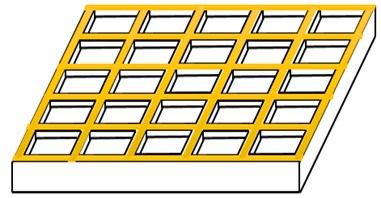
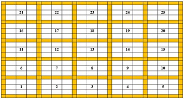
Table 1Comparisons of first three natural frequencies (Hz) and half-power bandwidth (HP) of the partially treated MR plate under magnetic flux density of 30 and 50 mT
Field (mT) | Method | First mode | Second mode | Third mode | |||
HP | HP | HP | |||||
30 | FE | 19.24 | 5.10 | 38.47 | – | 85.32 | 3.99 |
EXP | 18.16 | 5.35 | 43.00 | – | 86.55 | 2.70 | |
50 | FE | 19.27 | 5.05 | 38.56 | – | 85.98 | 4.01 |
EXP | 18.20 | 5.15 | 43.66 | – | 87.20 | 2.80 | |
Table 2The optimally treated cavities in the core layer of the SSSS sandwich plate resulting in maximum variations in first three natural frequencies in response to the applied magnetic flux
Mode | Cavity number | 0 mT | 90 mT | % change | |||
First | 2, 3, 4, 23, 24 | 80.96 | 0.0251 | 102.99 | 0.0907 | 27.21 | 261.35 |
Second | 8, 11, 13, 15, 18 | 138.09 | 0.0170 | 165.77 | 0.0687 | 20.04 | 304.12 |
Third | 3, 8, 13, 18, 23 | 181.19 | 0.0133 | 220.32 | 0.0663 | 21.60 | 398.50 |
The results also showed more significant shear deformation of the treated cavities compared to the untreated cavities. This is evident from Fig. 3, which illustrates distribution of nodal shear strain of the untreated SSSS plate corresponding to first mode. The plate is discretized to a mesh of 21×21 elements and a total of 400 nodes with nodes being numbered from A to B. The nodes with highest shear strain in the core layer are indicated by bold dots. First 80 nodes with highest shear strain amplitude in the core layer (number of nodes contained in five cavities) are identified on the discretized plate FE model for the first mode (Fig. 3). It is evident that the shear strain corresponding to the first mode is maximum around first and fifth rows (cavity # 2, 3, 4, 23 and 24), which is in agreement with the results presented in Table 2.
The solution of optimization problem in Eq. (5), ‘case 2’, provides optimal locations of MR-fluid treatments so as to maximizing the summation of the objective functions corresponding to the first three modes. For this case, the optimal treated cavities are found to be at locations 3, 13, 15, 23 and 24. The identified cavities revealed relatively higher shear strains in lower three modes of the structure. For example, the results in Table 2 suggest highest shear strain near cavity #3 in the first and third modes or cavity #13, which is common between the second and third l modes.
The optimization problems formulated in Eqs. (6) and (7) were solved to obtain optimal MR treatment locations of the CFFF plate resulting in maximum loss factors and thereby damping corresponding to lower three modes under 90 mT, while the maximum number of treated cavities was limited to 5 ( 5). Tables 3 summarizes optimal locations of MR fluid segments as well as maximum loss factor corresponding to each mode. The results obtained by optimizing summation of loss factors corresponding to the lower three modes suggested optimal cavities as 6, 15, 21, 22 and 24, which are generally comparable to those identified for the individual modes.
Fig. 3The shear strain distribution in the core layer of untreated SSSS sandwich plate in the first mode
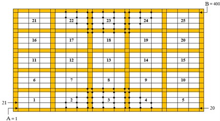
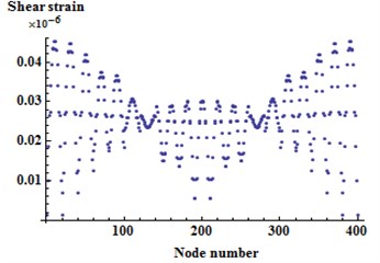
Table 3The optimal treated cavities of CFFF sandwich plate resulting under B= 90 mT
B.C. | Mode | Pocket number | |
CFFF | First | 6, 11, 12, 16, 21 | 0.0957 |
Second | 15, 21, 22, 23, 24 | 0.0995 | |
Third | 19, 21, 22, 24, 25 | 0.1172 |
5. Conclusions
The stiffness and damping properties of a partially treated MR sandwich plate were investigated through experiments and finite element analysis. The results suggest that in addition to the magnetic flux density and geometric boundary conditions, the locations of optimal MR fluid treatments have significant effect on the stiffness and damping properties of the partially treated MR sandwich plates. Furthermore, it could be realized that the optimal MR segments, irrespective of the boundary conditions and modes of vibration, were mostly located near particular cavities with noticeable shear strain.
References
-
Kciuk M., Turczyn R. Properties and application of magnetorheological fluids. Journal of Achievements in Materials and Manufacturing Engineering, Vol. 18, Issue 1, 2006, p. 127-130.
-
Rajamohan V., Rakheja S., Sedaghati R. Vibration analysis of partially treated multi-layer beam with magnetorheological fluid. Journal of Sound and Vibration, Vol. 329, 2010, p. 3451-3469.
-
Wang H. J., Chen L. L. Vibration and damping analysis of annular plates with constrained damping layer treatments. Journal of Sound and Vibration, Vol. 264, 2003, p. 893-910.
-
Oyadiji S. O. Applications of electro-rheological fluids for constrained layer damping treatment of structures. Journal of Intelligent Material Systems and Structures, Vol. 7, 1996, p. 541-546.
-
Cho K. D., Lee I., Han J. H. Dynamic characteristics of ER fluid-filled composite plate using multielectrode configuration. Journal of Intelligent Material Systems and Structures, Vol. 16, 2005, p. 411-419.
-
Mohammadi F., Sedaghati R. Vibration analysis and design optimization of sandwich cylindrical panels fully and partially treated with electrorheological fluid materials. Journal of Intelligent Material Systems and Structures, Vol. 23, Issue 15, 2012, p. 1679-1697.
-
Bai J. M., Sun C. T. The effect of viscoelastic adhesive layers on structural damping of sandwich beams. Mechanics of Structures and Machines, Vol. 23, Issue 1. 1995, p 1-16.
-
Li W. H., Chen G., Yeo S. H. Viscoelastic properties of MR fluids. Smart Materials and Structures, Vol. 8, 1999, p. 460-468.
-
Eshaghi M., Rakheja S., Sedaghati R. An accurate technique for pre-yield characterization of MR fluids. Smart Materials and Structures, Vol. 24, Issue 6, 2014.
