Abstract
The axial vibration of cracked nanorods (carbon nanotubes) with arbitrary boundary conditions is studied. The nonlocal elasticity theory is used, and the crack severity is modeled by an axial spring representing the discontinuity in the axial displacement. The present model is set up by dividing the nanorod into two segments connected by an axial spring located at the cracked section. The axial displacement functions are sought as the combination of two Fourier sine series and Stokes’ transformation. Vibration frequencies of a nanorod for variant crack positions under different boundary conditions are calculated by means of the proposed method. The purpose of this study is mainly to present a general analytical method for the dynamical analysis of cracked nanorods with arbitrary boundary conditions (rigid or restrained) rather than to investigate a specific problem.
1. Introduction
Carbon nanotubes (CNTs) are acknowledged to have superior physical, chemical, mechanical and electronic properties for wide potential applications [1, 2], such as graphene transistors, gas detection, solar cells, ultracapacitors, diagnosis devices and ultrastrength composite materials. In addition, the CNTs are ultralight and are highly sensitive to its environment changes [3]. Classical continuum theories are often employed in order to understand the mechanical properties of CNTs [4-9]. However, atomistic simulations [10, 11] and experimental findings [12] have proved a significant size effect in the mechanical performance of material at micro and nano scale. The application of classical continuum theories may be questionable in the theoretical analysis of CNTs, since these theories lack the accountability of the small-scale effects. The different formats of size-dependent elasticity theories such as micro-polar elasticity theory [13-15], strain gradient elasticity theory [16], nonlocal elasticity theory [17], couple stress theory [18] and modified couple stress theory [19, 20], have received increasing attention in modeling small sized structures.
The nonlocal elasticity theory is widely recognized as one of the most powerful and reliable method in the study of CNTs. Several studies have been conducted in the last years aimed at the identification of mechanical properties in CNTs. Wave propagation in CNTs has been investigated by Lu et al [21] and Wang [22]. Static analysis of micro and nano structures has been explored by Wang and Liew [23]. Buckling, bending and vibration of nonhomogeneous nanotubes have been studied by Pradhan and Phadikar [24] using differential quadrature method. Reddy [25] has presented Timoshenko and the Euler-Bernoulli beam theories using the nonlocal differential constitutive relations of Eringen [26]. Free axial vibration of the CNTs has been considered by Aydogdu [27]. A single nonlocal beam model has been proposed by Pradhan and Murmu [28] to investigate the bending and vibration characteristics of a nanocantilever beam. Torsional buckling problem of carbon nanotubes has been solved by Khademolhosseini et al. [29]. Mechanical behavior of carbon nanotubes embedded in polymer or metal matrix has been investigated by several researchers [30-35]. The nonlocal elasticity theory has been also used in the nonlinear vibration analysis of carbon nanotubes [36]. However, fewer researches have been so far conducted on the vibration behavior of cracked CNTs using nonlocal elasticity theory [37, 38].
The mechanical properties of cracked nanorods play an important role in process such as ZnO nanorods and nanowires. Due to different causes, the transverse open or breath cracks are often found in the nano-sized structures. Any cracks or defects in a nanorod reduce its vibration frequencies since it becomes more flexible. This fact has been used to detect the location of cracks in a nano structural component like nanorods. The computation of these vibration frequencies may also be used to detect the severity of cracks in a nano sized structure. Recently, a nonlocal rod model has been adopted for the axial vibration analysis of cracked rods with rigid boundary conditions [39].
It is well known that in real supporting situations, idealized boundary conditions (clamped-clamped, clamped-free, simply supported) never occur and therefore there exist axial or rotational restraint or both. It is often a difficult step prediction of a modal displacement function capable of satisfying any arbitrary restrained boundary conditions. Ansari and Darvizeh [40] have investigated vibrations of functionally graded shells under various edge conditions. By using Fourier sine series and Stokes’ transformation, vibration analysis of a beam on elastic foundation with elastically restrained ends has been investigated by Yayli et al. [41]. Kim and Kim [42] have studied the vibration of an Euler-Bernoulli beam with generally restrained boundary conditions by the same approach. A compact analytical method has been proposed to calculate vibrational frequencies of of single-walled carbon nanotubes with restrained boundary conditions by Yayli [43]. As far as authors’ knowledge however, there has been no study concerning the longitudinal vibration of a cracked nanorod with restrained boundary conditions.
The models of cracked nanorods may be divided into two groups: “lumped flexibility” models and “continuous” models. In this work, we utilize the technique of “lumped flexibility models”, whose main characteristic is that the presence of a crack is modeled via change of the stiffness of nanorods at the place of the crack, which is equivalent to the stiffness of an inserted massless axial spring. In this work, an attempt is made to present a new analytic method for vibration analysis of a cracked nanorod with deformable boundary conditions. Both Fourier sine series and Stokes’ transformation are employed to construct the simultaneous equations for eigenvalue analysis. Using the coefficient matrix developed in this study, longitudinal vibration frequencies of a cracked nanorod with arbitrary boundary conditions can be easily computed. The obtained coefficient matrix can be useful in theoretical investigation that leads to determinant calculation of a 4×4 matrix. The present procedure for the free vibration analysis of a nanorod with a crack is found to be effective regardless of the boundary conditions. Influences of different parameters on vibration frequencies are studied and discussed. The proposed analytical method can efficiently be used in detecting crack severity and location in nanostructures (carbon nanotubes, nanoparticles, nanorods, and nanoelectromechanical systems or microelectromechanical systems) with arbitrary boundaries. Furthermore it can be used to predict the critical load of damaged nanostructures based on eigenfrequency measurements.
2. Axial vibration of nanorod with nonlocal rod theory
A cracked nanorod with deformable boundary conditions as shown in Fig. 1 has length L and longitudinal uniform circular cross section with one traversed crack located at l1. The following nonlocal differential equation is often used [17]:
where ε and C are the fourth order strain and elasticity tensors, respectively. α is an internal characteristic length and e0 is a constant. Eq. (1) can be written in the following one dimensional form:
where E is the modulus of elasticity. The equation of motion for the axial vibration can be obtained as:
where m is the mass per unit length, u(x,t) is the axial displacement and Nl is the axial force for local elasticity. Nl can be defined by:
where A is the cross-sectional area of the nanorod. Using Eqs. (2)-(4) the following equation can be found in terms of axial force:
By substituting Eq. (5) into Eq. (3), the equation of the motion of the nonlocal nanorod model in terms of the axial displacement as follows [27]:
Due to the fact that the crack separates the nanorod into two parts, the axial displacements cannot be defined by a single function, therefore, two axial displacement functions are required. The nanorod is assumed to be divided into two parts by the crack. Consequently, the above differential equation can be rewritten as:
In order to solve the Eqs. (7), (8) investigators preferred the separation of variables method like reference [39]. However, with the separation of variables method the above coupled differential equations cannot be related to the restrained boundary conditions. Therefore, another type of transformation should be employed to solve this non classical boundary value problem.
3. Dynamic analysis of cracked nanorods with deformable boundary conditions
The researchers have introduced experimentally one type of vacancy defect in nanorods known as a slit defect. In fact, the absence of one or more atoms in the structural of nanorods causes the additional strain energy which is modeled as a crack in the continuum model. In this section, the cracked nanorod with deformable boundary conditions for a longitudinal vibration is explored based on the nonlocal elasticity theory. The cracked nanorod is represented by two rod segments connected with a axial spring of stiffness k, where the right segment is after the crack section and the left segment is before the crack section (Fig. 1). This model promotes a discontinuity in axial deflection. Both nanorod segments have the same material properties: cross-section area A, Young’s modulus E and the nonlocal parameter e0a.
3.1. Modal displacement functions
A spring is used to substitute the effect of crack on the vibration. The axial displacements over the two elements are denoted by u1(x,t) and u2(x,t). Assuming harmonic vibrations, u1(x,t) and u2(x,t) can be written in the following form:
where ξ(x) and ζ(x) are the modal displacement functions and ω is the natural frequency. The modal displacement functions both ξ(x) and ζ(x) are described in three separate regions, two for boundary points and the other for the intermediate region between the boundary points:
where:
The modal displacement functions in Eqs. (11) and (12) may be chosen either as a Fourier cosine series or as a sine series. In the present work, we consider two Fourier sine series.
Fig. 1A cracked nanorod with deformable boundary conditions

a) Sketch of a cracked nanorod with elastically restrained ends

b) Model of the cracked nanorod with elastically restrained ends
3.2. Stokes’ transformation
The Fourier coefficients (An) in Eq. (11) can be conveniently written as:
Termwise differentiation of Eq. (11) yields:
Above equation can be represented by a Fourier cosine series as follows:
The coefficients are given by:
the fn coefficient is obtained by integrating by parts of using Eq. (19):
The above procedure is known as Stokes’ transformation. To compute the exact series expressions for the first and higher order derivatives of a Fourier sine series, Stokes’ transformation must be utilized. The first and second derivatives of ξ(x) can be separately determined by employing Stokes’ transformation as follows:
The first two derivatives of Eq. (12) can be obtained with the use of the similar procedure:
Substituting Eqs. (9), (10), (23) and (25) into Eqs. (7) and (8), the Fourier coefficients An and Bn can be written in terms of ξ0, ξl1, ζ0 and ζl2 as follows:
where:
The explicit expressions of the axial displacements become:
where:
The inclusion of the scale parameter (e0a)2 in the above two equations takes into account the nonlocal effects.
4. Nonlocal boundary and jump conditions
A nanorod of length L and with one crack is considered as in Fig. (1). It is assumed that the crack is located at point l1. The entire nanorod has been divided into two segments with lengths l1, l2, respectively. Using Eqs. (3) and (5), the nonlocal axial force N can be expressed as:
Based on Eq. (34) it is then seen that the following boundary conditions at the spring locations can be written as:
where s0 and sL are the stiffnesses of the springs at the ends of the nanorod. Finally, the jump conditions are given as [45]:
where k is the crack flexibility constant. After some mathematical manipulations, the substitution of Eqs. (9), (10), (22) and (24) into Eqs. (35)-(38) leads to the four simultaneous homogeneous equations:
+(1-γ2λ2+∑∞n=12γ2δ21λ4(-1)n-2δ21λ2(-1)n-δ21λ2-π2γ2λ2n2+π2n2)ξl1=0,
+(γ2λ2-δ2SL-1+∑∞n=12δ22λ2-2γ2δ22λ4-δ22λ2-π2γ2λ2n2+π2n2)ζl2=0,
+(-γ2λ2+δ1K+1+∑∞n=12γ2δ21λ4(-1)n-2δ21λ2(-1)n-δ21λ2-π2γ2λ2n2+π2n2)ξl1-δ1Kζ0=0,
+(1δ1-∑∞n=12δ1λ2-δ21λ2-π2γ2λ2n2+π2n2)ξl1
+(1δ2-∑∞n=12δ2λ2-δ22λ2-π2γ2λ2n2+π2n2)ζ0
+(-1δ2-∑∞n=12δ2λ2(-1)n-δ22λ2-π2γ2λ2n2+π2n2)ζl2=0,
where:
and the frequencies of a cracked nanorod with different boundary conditions can be obtained by the following eigenvalue equation:
where:
Eq. (47) defines a classical eigenvalue problem. The eigenvalues (λn) are computed by setting the determinant of the coefficient matrix in Eq. (47) to zero:
It can be seen quite readily that there are only six parameters, γ, δ1, δ2, K, S0 and SL, in the expression of |ψij|=0. The characteristic equation of Eq. (60) can be solved by assigning the proper values of S0 and S1 corresponding to any specified boundary conditions. This procedure can be generalized to general nanorod systems as segments connected by elastic massless axial springs illustrating cross-sectional flexibilities. Afterward, jump conditions in Eqs. (37), (38) for free vibrations are established for each segment. The characteristic equation is then calculated as a nth-order determinant, equated to zero. As a result the eigenvalues of the problem may be explicitly obtained analytically.
Omitting the Eqs. (37), (38) and setting ξl1, ζ0 equal to zero one obtains two homogeneous algebraic equations for uncracked case including ξ0 and ζl2. The eigenvalue equation can be established by setting the δ1 and δ2 equal to one:
where:
5. Numerical results and discussion
In this section, several numerical examples are detailed to demonstrate the validity of the presented modelling and solution, also quantifying and highlighting the effects of the crack parameter K and nonlocal parameter γ on the dynamic response of the nanorods. The calculated values are computed using 60 terms in Eq. (60).
5.1. Verification studies
Prior to presentation of analytical results of the vibration frequencies, let us explore the accuracy and validity of the method proposed here. In order to validate the derived expressions, as well as to demonstrate their implementation, a cracked nanorod with hard axial springs is considered. The axial spring parameters are (For the large spring parameters, this problem essentially turns into the clamped-clamped case), the crack is located at any distance from the left. The crack parameter taken as for non-cracked nanorod. The comparison results for the vibration frequencies of the non-cracked nanorod for different modes are listed in Table 1. It can be seen that the present results are in good agreement with the previous studies.
In the second validation study, and parameters are similar to first example and the other spring parameter is taken as zero means that there is no axial spring at this boundary, namely, the nanorod is free at this end. The comparison results are listed in Table 2. The results are good agreement with those obtained from previous studies. In addition, the comparison of the results calculated by using the proposed method and that computed by Hsu et al. [39] and Singh [45] are listed in Table 3. The following parameters are used: γ= 0, δ1=0.202 and K= 0.1144. It is clear that the accuracy of solution is responsive to the number of terms from the infinite Fourier sine series. In the present study, a good convergence is seen for the first terms.
Table 1Comparison of the first three frequency parameters of nanorod with clamped ends
Clamped-Clamped | S0=SL=10000 | ||
Mode | Ref. [27] | Ref. [44] | Present |
λi | λi | λi | |
1 | 3.141 | 3.141 | 3.14259 |
2 | 6.284 | 6.283 | 6.28095 |
3 | 9.425 | 9.424 | 9.42368 |
Table 2Comparison of the first three frequency parameters of nanorod with clamped-free ends
Clamped-Free | S0= 10000, SL=0 | ||
Mode | Ref. [27] | Ref. [44] | Present |
λi | λi | λi | |
1 | 1.571 | 1.570 | 1.57539 |
2 | 4.712 | 4.712 | 4.73481 |
3 | 7.854 | 7.853 | 7.85398 |
Table 3Comparison of the first three frequency parameters of cracked nanorod with clamped-free ends
Clamped-Free | S0= 10000, SL=0 | ||
Mode | Ref. [39] | Ref. [45] | Present |
λi | λi | λi | |
1 | 1.4278 | 1.4278 | 1.42668 |
2 | 4.5576 | 4.5579 | 4.51172 |
3 | 7.8540 | 7.8540 | 7.85595 |
5.2. Parameter studies
In this section, the axial vibration of the considered nanorod is investigated and some results are compared with the results available in the literature. First frequency parameter of the cracked nanorod is presented in Table 4 for various values of spring (S0, SL), crack K and nonlocal parameters γ. The results in this table are obtained by using Eq. (60) for the constant value of δ1=0.35. It may be noted that for the results given under the S0=SL= 10000 and S0=10000, SL=0 columns in Table 4 corresponding to the rigid boundary conditions (clamped-clamped, clamped-free). Since there is no reported work for the vibration of cracked nanorods with elastic restraints as far as the authors know, it is believed that the listed results in Tables 4 and 5 will be a reference with which other researchers can compare their studies.
Table 4Variation of the first frequency parameter (λi) for various values of SL, S0 and K
γ | Clamped-Free | Present | ||
K= 0 | K= 0 | K= 0 | K= 0 | |
Ref. [27] | S0= 10000, SL=0 | S0= 10, SL=30 | S0= 10, SL=5 | |
0 | 1.570 | 1.576 | 2.3958 | 2.0289 |
0.02 | 1.570 | 1.576 | 2.3934 | 2.0280 |
0.04 | 1.567 | 1.573 | 2.3867 | 2.0255 |
0.06 | 1.563 | 1.569 | 2.3755 | 2.0214 |
0.08 | 1.558 | 1.564 | 2.3600 | 2.0155 |
0.10 | 1.551 | 1.557 | 2.3487 | 2.0080 |
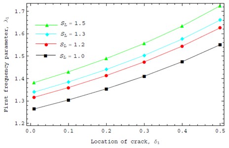
Fig. 2 shows the variation of first vibration parameter of cracked nanorod with the location of crack. The crack severity and left spring parameter are assumed to be constant, K= 1, S0=5. The nonlocal results are given for SL=1.0, SL=1.2, SL= 1.3 and SL=1.5, respectively. In this example, the location of crack varies from δ1=0.01 to δ1=0.5. It can be concluded from the figure that the influence of a crack on the dynamic behavior of the nanorod is sensitive to its location. One can observe that the first vibration parameter increases and the spring parameter SL increases as the δ1 increases. This is due to the fact that the elastic strain energy decreases as the crack location is closer to the hard boundary condition.
Table 5Variation of the first frequency parameter (λi) for various values of, SL, S0 and K
γ | Clamped-Free | Present | ||
K= 0 | K= 0 | K= 0.5 | K= 1.0 | |
Ref. [27] | S0=SL=10000 | S0=SL= 1 | S0=SL= 2 | |
0 | 3.141 | 3.140 | 1.2750 | 1.6088 |
0.02 | 3.135 | 3.134 | 1.2748 | 1.6086 |
0.04 | 3.117 | 3.116 | 1.2746 | 1.6080 |
0.06 | 3.087 | 3.086 | 1.2743 | 1.6069 |
0.08 | 3.046 | 3.046 | 1.2738 | 1.6053 |
0.10 | 2.997 | 2.997 | 1.2733 | 1.6033 |
Fig. 2Effect of the crack position on dynamic behavior for different boundary conditions
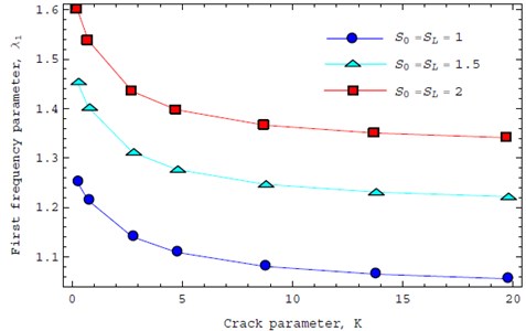
The changes of the first frequency parameter in the case that a crack located at its middle section δ1= 0.5 with same values of nonlocal parameter γ= 0.1 and different values of crack parameter K are presented in Fig. 3. A cracked nanorod is considered with the boundary conditions S0=1, 1.5, 2.0 at left end and S0=1, 1.5, 2.0 at right end as a symmetric boundaries. It is seen that crack reduces the vibration frequencies because the nanorod stiffness decreases. This is as expected since a crack represents a loss of material. This will be used to detect the location of the crack in a nanostructure.
Fig. 3First vibration frequencies as a function of crack severity K located at its middle section
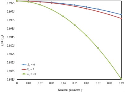
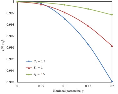
The effect of the nonlocal parameter on the dynamic behaviour of cracked nanorod is demonstrated in Fig. 3. This figure displays the first normalized natural frequency ratios, as a function of nonlocal parameter for selected spring parameter S0=1000, crack severity K= 0.5, and crack position δ1=0.4. The most important observations are as follows. The differences between the nonlocal theory and those of the local theory increase, as the nonlocal parameter γ increases, especially for the higher spring parameters (SL). The frequency ratios decrease rapidly at higher values of the spring parameters. The effects of different boundary conditions and nonlocal parameter on the frequencies of cracked nanorod are also presented in Fig. 3. The left spring parameter S0 and crack severity K are assumed to be 1.5 and 5, respectively. Fixing the crack position at δ1=0.1 and varying the nonlocal parameter γ results in a significant change in the frequency parameter ratios. One can note as the nonlocality parameter γ increases, the frequency parameter ratios decreases, which highlights the significance of the small scale effect.
Fig. 4First vibration frequencies as a function of nonlocal parameter
a)
b)
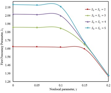
The first frequency parameter of the cracked nanorod with crack severity (K= 0.1144) is shown in Fig. 5. The following parameters are used: δ1=0.2002, γ= 0.1. The effect of deformable boundary conditions (S0, SL) is investigated in this example. All frequencies decrease with an increase of the nonlocal parameter. In addition, the effect of the nonlocal parameter on the frequencies is significant for the higher values of the spring stiffnesses S0, SL, especially, for the clamped-clamped case. The small scale effect is taken into consideration in the vibration analysis that makes the nanorod stiffer. Therefore, a higher small scale parameter γ leads to a decrease of the crack effect on the vibration frequency.
Fig. 5First vibration frequencies as a function of nonlocal parameter for a cracked nanorod
6. Conclusions
On the basis of the nonlocal elasticity theory, the longitudinal vibration behavior of cracked nanorods with deformable boundary conditions was studied by implementing Stokes’ transformation. Crack was modeled by an axial spring representing the discontinuity in the axial displacement. The nanorod was assumed to be divided into two parts by the crack. Using two Fourier sine series, frequency determinant was derived and the vibration frequencies were determined by the characteristic equation. Presented results were confirmed by the results via using a cracked nanorod with rigid boundary conditions. The conclusions are itemized below:
1) By using this method, the eigenvalue equation for a cracked nanorod with any kinds of boundary conditions can be conveniently determined from a fourth order determinant. It is not necessary to sellect a new set of displacement functions for each change in supporting conditions.
2) Influence of a crack on the dynamic behavior of the nanorod is sensitive to its location.
3) The vibration frequency of nanorods is shown to be dependent on the crack position and the end conditions.
4) It is observed that the influences of crack severity, nonlocal parameter and location of crack on the vibration frequency of the cracked nanorod are significant.
5) The small scale effects are more prominent for hard springs compared to the soft ones.
6) The frequency parameter decreases with an increase of the crack severity for the nanorod with any boundary conditions.
7) A larger small scale parameter leads to a decrease of the crack effect on the vibration frequency.
References
-
Kim P., Lieber C. M. Nanotube nanotweezers. Science, Vol. 286, 1999, p. 2148-2150.
-
Bachtold A., Hadley P., Nakanihi T., Dekker C. Logic circuits with carbon nanotube transistors. Science, Vol. 294, 2001, p. 1317-1320.
-
Wong E. W., Sheehan P. E., Lieber C. M. Nanobeam mechanics: elasticity, strength and toughness of nanorods and nanotubes. Science, Vol. 277, 1997, p. 1971-1975.
-
Mehdipour I., Barari A., Domairry G. Why the center-point of bridged carbon nanotube length is the most mass sensitive location for mass attachment? Computer Materials Science, Vol. 55, 2012, p. 136-141.
-
Joshi A. Y., Harsha S. P., Sharma S. C. Vibration signature analysis of single walled carbon nanotube based nanomechanical sensors. Physica E, Vol. 42, 2010, p. 2115-2123.
-
Wu D. H., Chien W. T., Chen C. S., Chen H. H. Resonant frequency analysis of fixed-free single-walled carbon nanotube-based mass sensor. Sensors and Actuators A, Vol. 126, 2006, p. 117-121.
-
Arroyo M., Belytschko T. Continuum mechanics modeling and simulation of carbon nanotubes. Meccanica, Vol. 40, Issue 4-5, 2005, p. 455-469.
-
Wan H., Delale F. A structural mechanics approach for predicting the mechanical properties of carbon nanotubes. Meccanica, Vol. 45, Issue 1, 2010, p. 43-51.
-
Chowdhury R., Adhikari S., Mitchell J. Vibrating carbon nanotube based biosensors. Physica E, Vol. 42, 2009, p. 104-109.
-
Li C. Y., Chou T. W. A structural mechanics approach for the analysis of carbon nanotubes. International Journal Solids Structural, Vol. 40, 2003, p. 2487-2499.
-
Chowdhury R., Adhikari S., Wang C. W., Scarpa F. A molecular mechanics approach for the vibration of single walled carbon nanotubes. Computer Materials Science, Vol. 48, 2010, p. 730-735.
-
Poncharal P., Wang Z. L., Ugarte D., Heer W. A. D. Electrostatic detections and electromechanical resonances of carbon nanotubes. Science, Vol. 283, 1999, p. 1513-1516.
-
Eringen A. C., Suhubi E. S. Nonlinear theory of simple micro-elastic solids-I. International Journal of Engineering, Science, Vol. 2, 1964, p. 189-203.
-
Chen Y., Lee J. D., Eskandarian A. Atomistic viewpoint of the applicability of microcontinuum theories. International Journal of Solids and Structures, Vol. 41, 2004, p. 2085-2097.
-
Ramezani S., Naghdabadi R., Sohrabpour S. Analysis of micropolar elastic beams. European Journal of Mechanics-A/Solids, Vol. 28, Issue 2, 2009, p. 202-208.
-
Yayli M. O. Stability analysis of a gradient elastic beam using finite element method. International Journal of Physical Science, Vol. 6, Issue 12, 2011, p. 2844-2851.
-
Eringen A. C. On differential equations of nonlocal elasticity and solutions of screw dislocation and surface waves. Journal of Applied Physics, Vol. 54, 1983, p. 4703-4710.
-
Toupin R. A. Elastic materials with couple-stresses. Archive for Rational Mechanics and Analysis, Vol. 11, 1962, p. 385-414.
-
Ma H. M., Gao X.-L., Reddy J. N. A microstructure-dependent Timoshenko beam model based on a modified couple stress theory. Journal of the Mechanics and Physics of Solids, Vol. 56, Issue 12, 2008, p. 3379-3391.
-
Park S. K., Gao X.-L. Bernoulli-Euler beam model based on a modified couple stress theory. Journal of Micromechanics and Microengineering, Vol. 16, Issue 11, 2006, p. 2355-2359.
-
Lu P., Lee H. P., Lu C., Zhang P. Q. Application of nonlocal beam models for carbon nanotubes. International Journal of Solids Structures, Vol. 44, 2007, p. 5289-5300.
-
Wang Q. Wave propagation in carbon nanotubes via nonlocal continuum mechanics. Journal of Applied Physics, Vol. 98, 2005, p. 124301.
-
Wang Q., Liew K. M. Application of nonlocal continuum mechanics to static analysis of micro- and nano-structures. Physics Letters A, Vol. 363, 2007, p. 236-242.
-
Pradhan S. C., Phadikar J. K. Bending, buckling and vibration analyses of nonhomogeneous nanotubes using GDQ and nonlocal elasticity theory. Structural Engineering Mechanics, Vol. 33, 2009, p. 193-213.
-
Reddy J. N., Pang S. D. Nonlocal continuum theories of beams for the analysis of carbon nanotubes. Journal Applied Physics, Vol. 103, 2008, p. 23511-23526.
-
Eringen A. C., Edelen D. G. B. On nonlocal elasticity. International Journal of Engineering Science, Vol. 10, 1972, p. 233-248.
-
Aydogdu M. Axial vibration of the nanorods with the nonlocal continuum rod model. Physica E, Vol. 41, 2009, p. 861-864.
-
Pradhan S. C., Murmu T. Buckling of single layer graphene sheet based on nonlocal elasticity and higher order shear deformation theory. Physics Letters A, Vol. 373, 2010, p. 4182-4188.
-
Khademolhosseini F., Rajapakse R. K. N. D., Nojeh A. Torsional buckling of carbon nanotubes based on nonlocal elasticity shell models. Computational Materials Science, Vol. 48, 2010, p. 736-742.
-
Wang L., Ni Q., Li M., Qian Q. The thermal effect on vibration and instability of carbon nanotubes conveying fluid. Physica E, Vol. 40, 2008, p. 3179-3182.
-
Ru C. Q. Axially compressed buckling of a doublewalled carbon nanotube embedded in an elastic medium. Journal of the Mechanics and Physics of Solids, Vol. 49, 2001, p. 1265-1279.
-
Schadler L. S., Giannaris S. C., Ajayan P. M. Load transfer in carbon nanotube epoxy composites. Applied Physics Letters, Vol. 73, 1998, p. 3842-3844.
-
Qian D., Dickey E. C., Andrews R., Rantell T. Load Transfer and deformation mechanisms in carbon nanotube-polystyrene composites. Applied Physics Letters, Vol. 76, 2000, p. 2868-2870.
-
Wagner H. D., Lourie O., Feldman Y., Tenne R. Stress-induced fragmentation of multiwall carbon nanotubes in a polymer matrix. Applied Physics Letters, Vol. 72, 1998, p. 188-190.
-
Bower C., Rosen R., Jin L., Han J., Zhou O. Deformation of carbon nanotubes in nanotubepolymer composites. Applied Physics Letters, Vol. 74, 1999, p. 3317-3319.
-
Yang J., Ke L. L., Kitipornchai S. Nonlinear free vibration of single-walled carbon nanotubes using nonlocal Timoshenko beam theory. Physica E, Vol. 42, 2010, p. 1727-1735.
-
Roostai H., Haghpanahi M. Vibration of nanobeams of different boundary conditions with multiple cracks based on nonlocal elasticity theory. Applied Mathematical Modelling, Vol. 38, Issue 3, 2014, p. 1159-1169.
-
Loya J. A., Aranda-Ruiz J., Fernandez-Saez J. Torsion of cracked nanorods using a nonlocal elasticity model. Journal of Physics D: Applied Physics, Vol. 47, Issue 3, 2014, p. 115304.
-
Hsu J. C., Lee H. L., Chang W. J. Longitudinal vibration of cracked nanobeams using nonlocal elasticity theory. Current Applied Physics, Vol. 11, 2011, p. 1384-1388.
-
Ansari R., Darvizeh M. Prediction of dynamic behavior of FGM shells under arbitrary boundary conditions. Composites of Structures, Vol. 85, 2008, p. 284-292.
-
Yayli M. O., Aras M., Aksoy S. An efficient analytical method for vibration analysis of a beam on elastic foundation with elastically restrained ends. Shock and Vibration, 2014, p. 159213.
-
Kim H. K., Kim M. S. Vibration of beams with generally restrained boundary conditions using Fourier series. Journal of Sound Vibration, Vol. 245, Issue 5, 2001, 771-784.
-
Yayli M. O. A compact analytical method for vibration analysis of single-walled carbon nanotubes with restrained boundary conditions. Journal of Vibration and Control, 2014.
-
Kumar B. M., Sujith R. I. Exact solutions for the longitudinal vibration of nonuniform rods. Journal Sound and Vibration, Vol. 207, 1997, p. 721-729.
-
Singh K. V. Transcendental inverse eigenvalue problems in damage parameter estimation. Mechanical Systems and Signal Processing, Vol. 23, 2009, p. 1870-1883.
