Abstract
Translating robot manipulators (TRMs) especially flexible translating robot manipulators (FTRMs) have been actively used in takeout robots, beam-type substrate transport robots and manufacturing machines and it remains that the end-effector on robot arms should have a good operating accuracy. Due to the coupling effect, such as motor parameters and mechanism inertias, the motions of the driving stage exhibits certain disturbances especially in high speeds. Considering the influence of the motion disturbances, this paper models the motions of the driving stage as harmonic driving motions and in this case the FTRM is similar to a parametrically excited system. The multiple scales method is applied to obtain the stability conditions for the motion disturbances. Based on the established coupling dynamic model, the influences of the motion disturbances on the vibration behaviors and the stability are investigated. Moreover, considering the actual motion characteristics of the driving stage with varied accelerations and velocities, the effect mechanism between the motion characteristics and motion disturbances are subsequently studied. According to this effect mechanism, the influence of the motion disturbances can be suppressed through motion optimizing, which is meaningful for motion optimizations and vibration controls of the FTRM. An ADAMS physical prototype is constructed to verify the dynamic model and theoretical analysis results, and the results have a good agreement.
1. Introduction
Translating robot manipulators (TRMs) are widely used in various industrial applications, such as takeout robots, also known as injection-molding machines [1], beam-type substrate transport robots [2, 3] and manufacturing machines [4]. Driven by the driving unit, the end-effector clamped on the arm can execute the corresponding tasks, such as takeout of materials, metalworking, and assemblage and package of tiny parts. In most time, the executing tasks and objects are tedious, tiny and even dangerous, which remains that the end-effector should have a good executing accuracy and longtime service life [5, 6]. To achieve this target, rigid translating robot manipulators (RTRMs) are accordingly constructed in a manner of maximizing the stiffness by using heavy materials and bulky structure designs [5, 7]. As a consequence, these RTRMs are relatively heavy which will limit the operation speed and contradicts the purpose of improving the productivity and energy utilization efficiency.
With the urgent request of high productivity, flexible translating robot manipulators (FTRMs) are actively developed and received increasing attentions in these and other fields [5, 8-12]. Compared with RTRMs, FTRMs have light weights and flexibilities and can meet the purpose of high productivity and energy utilization efficiency. It should be noted at the same time that, due to the damp and stiffness are generally lower, the FTRM surfers an issue about residual vibrations of its arm which are inevitable when executes the operation tasks, for example changes its position by suddenly translating following a command input, and significantly affect the operation precision and service life of the end-effector [5, 8]. Without controlling, the vibrations will persist for a period of time and consequently delay the subsequent operations and restrain the operating efficiency. Specially, if the FTRMs are used for micro surgeries, these residual vibrations may cause surgery failures and even life deaths [10-12]. Thus, the dynamics especially the vibration analysis of FTRMs is of significance for maximizing their advantages in engineering applications.
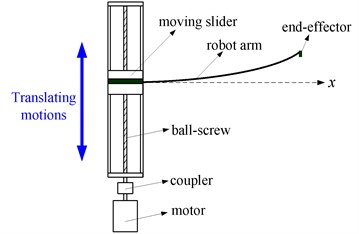
The detailed TRMs in takeout robots, beam-type substrate transport robots and manufacturing machines are Cartesian types which have translating and deploying motions. Each FTRM can be modeled as a flexible link with a translational base support [13], which can be clearly seen in [1, 14-18]. In these literatures, the motions velocities or accelerations of the ball-screw stage are regarded as constant without any fluctuations during the dynamic modeling and vibration controlling of FTRMs. In order to talk about this, a schematic diagram of the FTRM is presented in Fig. 1, in which only the translating motions are shown. Here, the arm clamps the end-effector and is driven by a ball-screw stage with motor driving. We can see that the FTRM is a typical electromechanical system containing drive, sensing and mechanical components. Due to the coupling effect of motor parameters and mechanism inertias, the motion velocities and accelerations of the ball-screw stage are not the ideal constant status and exhibit certain fluctuations especially in high speeds [13], which are relatively common in elastic linkage mechanisms [19-22] and however the related studies for robot manipulators are still limited. Lee [23] indicated that due to the unbalance mass of motor in different rotational speeds, the machine platform will surfer disturbances and varying excitation frequencies. Tuttle [24] discovered that the motion error mainly aroused by backlash between the splines. Thus, in the dynamic modeling and vibration investigating of FTRMs especially using harmonic drive, the motion disturbances of the driving stage should be considered, and ignoring the motion disturbances will cause an error and cannot reflect the actual dynamics of the FTRM especially for which need certain accuracies.
Fig. 1Schematic diagram of the FTRM
In this paper, we will consider the motion disturbances of the driving stage during the dynamic modeling and vibration behaviors investigation of the FTRM. In this case, the driving stage conveys disturbance excitations. Through investigating the influence of the motion disturbances on the vibration behaviors and stability, as well as the effect of motion characteristics of the driving stage on the motion disturbances, we attempt to obtain some meaningful results for further vibration control and driving optimization of the FTRM. The remainder of this paper is structured as follows. In Section 2, the dynamic model of the FTRM with motion disturbances is constructed, and the stability conditions for the motion disturbances are derived based on the coupling dynamic model. The coupling vibration characteristics of the FTRM are investigated in Section 3 as well as the results are presented and discussed. In Section 4, this paper is concluded with a brief summary.
2. Dynamic model of the FTRM
2.1. Vibration displacements equation
As indicated in Fig. 1, the FTRM is a typical electromechanical system. During the tasks executing, the dynamics of the flexible link and end-effector accordingly coupled by the dynamic behaviors of the ball-screw stage. As detailed in former, due to the influence of motor parameters and mechanism inertias, the driving motions of the driving stage will exhibit certain disturbances. According to [20-22], the motion disturbances have the features of harmonic functions. In [25], these harmonic drive motions are stated as the form of sinusoidal functions. Inspired by this, the harmonic functions can be expanded as the form of Fourier series. To simplify the analysis, we use sinusoidal functions to describe the harmonic functions. In this case, the driving motion of the driving stage can be written as:
where γ and ε denote the amplitudes and frequencies of the harmonic disturbances, respectively; s0(t) denotes the ideal constant motion of the driving stage which is generally considered in existent literatures. It can be obtained from Eq. (1) that the driving motion of the driving stage not only conveys the harmonic disturbances, but also can reflect the actual motion characteristics of the FTRM, which can be used to investigate the influence of the motion disturbances as well as the effect mechanism between the motion characteristics and the disturbances. Based on this, the dynamic model of the FTRM can be described in Fig. 2. Here, the arm is modeled as a flexible link with an end-effector, the driving stage has translating harmonic driving motions. Under harmonic excitations, the system is similar to a parametrically excited system [26] which is commonly reported in investigations of beams and plates with parametric excitations [27-30].
Fig. 2Dynamic model of the FTRM
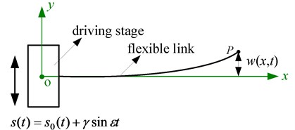
Driven by the driving stage, the flexible link and the end-effector can execute the tasks. To investigate the elastic deflections and vibrations during the executions, assumptions are made that the flexible link satisfies the Bernoulli-Euler Beam assumptions and the transverse vibrations in the x-y plane are the primary motions.
The absolute displacement of the end-effector can be expressed as:
here w(x,t) denotes the transverse vibration displacements of the flexible link and, according to the assumed modes method [31], can be expressed as:
where qi(t) denotes the ith generalized co-ordinate, ϕi(x) denotes the ith orthogonal mode shapes and can be given as:
where ωi denotes the ith natural frequency of the FTRM, L is the length of the flexible link.
The kinetic energy of the FTRM can be written as:
where ρ is the mass density, A is the cross-sectional area, A=b×h, b and h are the width and the thickness, respectively, ms is the mass of the moving slider of the driving stage, (∙) denotes the time derivative, y't denotes the partial derivative of y(x,t) with respect to t. Here, the first part represents the kinetic energy of the moving slider while the second part represents the kinetic energy of the flexible link.
Combining Eq. (2), Eq. (5) can be further expressed as:
where w,t denotes the partial derivative of w(x,t) with respect to t.
The potential energy of the FTRM mainly considers the bending elastic potential energy of the flexible link and can be written as:
where E is Young’s modulus, I is the cross-sectional moment of inertia about the neural axis, I=bh3/12, w'xx denotes the second order partial derivative of w(x,t) with respect to x.
To established the dynamic model, the Lagrangian function is introduced and written as:
and according to Hamilton’s principle [32], Eq.(8) satisfies following condition:
where:
=-∫t1t0∫L0ρA(¨s+w'tt)dxdtδw,
where w'tt denotes the second order partial derivative of w(x,t) with respect to t:
where w'x denotes the partial derivative of w(x,t) with respect to x, w'xxx denotes the third order partial derivative of w(x,t) with respect to x.
Substituting Eqs. (10) and (11) into Eq. (9):
=-∫t1t0∫L0[ρA(¨s+w'tt)+EIw'xxw'xxxw'x]dxdtδw=0,
it can be obtained that:
Combining Eq. (3), Eq. (13) can be further written as:
Multiplying Eq. (14) with ϕj and subsequently integrating the equation along the length direction, result can be obtained that:
According to the orthogonality of mode shapes [15, 33], the vibration displacements equation of the FTRM can be obtained as:
where mi=∫L0ρAϕidx.
It can be obtained from Eq. (16) that the vibration displacements of the FTRM are related with the actual motion characteristics of the driving stage.
Substituting Eq. (1) into Eq. (16), result can be obtained as:
Eq. (17) further reveals that the vibration responses of the FTRM is influenced by the motion disturbances and related with the actual motion characteristics of the driving stage. Therefore, to conduct an accurate dynamic analysis of the FTRM, the motion characteristics and disturbances of the driving stage should be comprehensively considered. To investigate the influence of the motion disturbances and the effect mechanism between the motion characteristics and disturbances, this paper considers the situations that the driving stage having average accelerations and velocities.
The driving motion of the driving stage can be described as:
here a denotes the ideal average acceleration which is generally considered in existent literatures.
Combining Eqs. (17) and (18), the vibration displacements equation of the FTRM can be further expressed as:
Via Duhamel integral [31], the response of the FTRM can be obtained as:
where B1i and B2i are coefficients determined by initial conditions which can be determined as:
where Mi=∫L0ρAϕi2dx.
Assigning a=0 in Eq. (20), the situation is that the driving stage having an average velocity. We can see that Eq. (20) contains the coupling effect of motion disturbances and motion characteristics. Thus, through assigning varied motion accelerations and velocities, the influence of the motion disturbances on the vibration behaviors as well as the effect mechanism between the motion characteristics and the motion disturbances can be investigated.
2.2. Stability conditions
It is known that when the disturbance frequencies are near the main resonance frequencies, the parametric resonances will be aroused [26, 34]. The multiple scales method is employed to obtain the stability conditions for the motion disturbances. The q in Eq. (19) can be expressed as:
here T0=t denotes the fast scale characterizing motion, and T1=αt denotes the slow scale characterizing motion.
Substituting Eq. (22) into Eq. (19), it can be obtained as:
A detuning parameter σ is introduced to quantify the deviation of ε from ωn, and in this case ε can be described as:
where ωn is the nth natural frequency of the FTRM.
To investigate the parametric responses, according to [35], the solution of Eq. (23) can be expressed as:
Substituting Eqs. (25) and (26) into Eq. (24), and expressing the trigonometric functions in exponential form yield:
where the dot denotes the derivation with respect to the slow time variable T1, cc denotes the complex conjugate of all preceding terms on the right hand, NST stands for the terms that will not bring secular terms into the solution.
The solvability condition demands the orthogonal relationships [36]:
Applying the distributive law of the inner product to Eq. (28), it can be obtained as:
According to [29] and [37], the stability boundary can be similarly expressed as:
3. Coupling vibration characteristics of the FTRM
In this section, numerical simulations are conducted to investigate the coupling vibration characteristics of the FTRM. As shown in Figs. 1 and 2, we use a flexible link to model the arm of the FTRM in the numerical simulations. Properties of the flexible link are length L=575 mm, width b=28 mm, thickness h=1 mm, Young’s modulus E=197 GPa, volumetric density ρ=7850 kg/m3 and Poisson’s ratio μ=0.26. In the computations, the initial conditions are assigned w(0.575,0)=–0.001 and w,t(0.575,0)=0.001, respectively.
Fig. 3 shows the steady-state vibration responses of the FTRM. It can be seen that for the driving stage having velocity motions and acceleration motions, the motion disturbances have noticeable influence on the vibration responses. The response amplitudes are obviously bigger than the ideal status which ignores the motion disturbances. This indicates that the motion disturbances will enlarge the vibration responses of the end-effector and arouse certain error during the analysis.
Fig. 3Steady-state vibration responses of the FTRM: a) a= 0.1 m/s2; b) v= 0.01 m/s

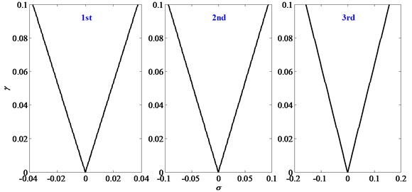
Fig. 4 further presents the influence of disturbance frequencies ε and disturbance amplitudes γ on the vibration responses of the FTRM. It can be obtained that, response amplitudes A increase with ε and γ, and when ε is near the main resonance frequencies, the response amplitudes enlarge obviously and arouse resonances. The stability boundaries for the first three principal resonances in plane σ-γ are shown in Fig. 5.
From Figs. 3 and 4, it can be obtained that disturbance frequencies and the disturbance amplitudes all have a considerable influence on the vibration responses. To compare the effect of the disturbance frequencies and disturbance amplitudes, Fig. 6 exhibits vibration responses of the FTRM under acceleration motions and velocity motions with different disturbance frequencies and disturbance amplitudes. The average acceleration and velocity are assigned a=0.1 m/s2 and v=0.01 m/s. It can be obtained that the response amplitudes increase with γ and ε, this is consistent with Fig. 4; moreover, the situations of γ=0.003, ε=5 and γ=0.001, ε=15 reveal that the influence of ε is more pronounced than γ, which indicates that the effect of disturbance frequencies is more noticeable than that of disturbance amplitudes and should be mainly considered in following dynamic analysis.
Fig. 4Influences of disturbance frequencies and disturbance amplitudes on the vibration responses

Fig. 5Stability boundaries for the first three principal resonances
It is known from Fig. 3 that during the motions of FTRM, the motion disturbances have noticeable influence and enlarge the vibration responses of the end-effector which will decrease the operation accuracy and service life of the system. According to Fig. 6, it is further indicated that the disturbance frequencies are the more significant factor and should be mainly considered. Accordingly, with the purpose of suppressing the influence of the disturbance frequencies and giving some useful suggestions for further vibration controls, Fig. 7 further studies the effect mechanism between the disturbance frequencies and motion accelerations and velocities. During the analysis, the disturbance amplitude is assigned γ=0.001 while the varied disturbance frequencies are assigned ε=0, ε=5 and ε=15.
Firstly, Fig. 7 indicates that the response amplitudes increase with disturbance frequencies, which is consistent with Figs.4 and 6. Moreover, it can be obtained from Fig. 7(a) that for smaller motion accelerations, the vibration responses with motion disturbances are significantly different with the ideal status which ignores the motion disturbances (ε=0) and have a noticeable error; with motion accelerations increasing, the error decreases and the vibration responses of different disturbance frequencies all gradually approximate with the ideal status of ε=0. This indicates that larger motion accelerations have suppressing effect on the influence of the disturbances frequencies and this can advise the motion control of the driving stage. From Fig. 7(b), it can be obtained that the vibration responses of different disturbance frequencies have noticeable error with the ideal status (ε=0); moreover, with motion velocities increasing, the vibration responses remain unchanged, which reveals that the motion velocities have no effect on the influence of motion disturbances. This effect mechanism between the disturbance frequencies and motion accelerations and velocities further indicates that the motion characteristics of the driven stage have influence on the dynamics of the FTRM and through motion optimizing of the driving stage, the influence of the motion disturbances can be suppressed, for example within the permission of conditions, the driving stage should utilize larger motion accelerations to execute tasks, which is meaningful for motion optimizations and vibration controls of the FTRM.
Fig. 6Comparison of the disturbance frequencies and disturbance amplitudes on the vibration responses: a) a= 0.1 m/s2; b) v= 0.01 m/s
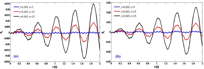
Fig. 7Effect mechanism between the disturbance frequencies and motion characteristics: a) acceleration motions; b) velocity motions

4. ADAMS prototype and experimental validation
As indicated in Fig. 1, under harmonic excitations, the FTRM system is a parametrically excited system. It should be noted that existent researches about parametrically excited system are mainly theoretical analysis and few related experimental investigations are conducted. In this section, to verify the established coupling dynamic model and analysis results, an ADAMS prototype of the FTRM is constructed. As shown in Fig. 8, to simplify the physical modeling, the flexible link is modeled as a flexible body, the moving slider of the driving stage is modeled as a solid mass which is assigned translating motions, and the restrain condition between the flexible body and solid mass is defined as fixed. The properties of the physical model are consistent with that of the numerical simulation.
Fig. 9 shows the vibration responses with varied motion accelerations and velocities. In the experimental simulations, the motion disturbance is assigned γ=0.001, ε=15. It indicates that the response amplitudes decrease with accelerations increasing and present a minor change for different motion velocities, which reveals that larger accelerations have suppression effect on the motion disturbance while motion velocities have no effect on the vibration responses. This change trend is consistent with the theoretical analysis in Fig. 7.
Fig. 8Prototype of the FTRM system
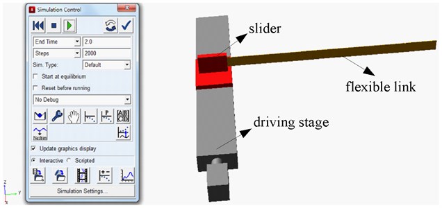
Fig. 9Validation of the effect mechanism between motion disturbances and motion characteristics: a) acceleration motions; b) velocity motions

Considering the prototype has acceleration motions and velocity motions which are assigned a=0.1 m/s2 and v=0.01 m/s in the experimental simulations, Fig. 10 presents the vibration responses with different motion disturbance status. It can be seen that the results of the physical prototype are good agreement with the theoretical analysis. It should be noted that the results exhibit a certain error especially in the initial stage, and this is mainly caused by the initial condition and structural damping which are ignored in the dynamic modeling. But the effect mechanism is well consistent.
Fig. 10Validation of the influence of motion disturbances: a) a= 0.1 m/s2; b) v= 0.01 m/s

5. Conclusions
Considering the influence of motion disturbances which are actually existent in the driving stage, this paper investigates the coupling vibration behaviors and stability of the flexible translating robot manipulator (FTRM). The results indicate that the motion disturbances have considerable influence on the vibration responses. For the driving stage having velocity motions and acceleration motions, the response amplitudes are obviously larger than the ideal status which ignores the motion disturbances, this indicates that the motion disturbances enlarge the vibration responses of the end-effector and should be considered in the dynamic investigations. Moreover, the response amplitudes increase with the disturbance frequencies and the disturbance amplitudes, and the disturbance frequencies have a more noticeable effect than the disturbance amplitudes, when the disturbance frequencies approach the main resonance frequencies, the response amplitudes enlarge obviously and arouse resonances. The effect mechanism between the disturbances and the motion characteristics reveals that larger motion accelerations have suppression effect on the motion disturbances while the motion velocities have no effect. According to this effect mechanism, within the permission of conditions, the driving stage should utilize larger motion accelerations to execute the tasks and in this case the influence of the motion disturbances can be suppressed, which can direct motion optimizations of the FTRM. The theoretical analysis results are well consistent with that of the ADAMS physical prototype, which reveals that the proposed coupling dynamic model can well reflect the dynamic behaviors of the FTRM. In our further work, we will conduct the vibration suppressing through motion optimizations and active vibration controls of the FTRM.
References
-
Byeongjin K., Jintai C. Residual vibration reduction of a flexible beam deploying from a translating hub. Journal of Sound and Vibration, Vol. 333, Issue 16, 2014, p. 3759-3775.
-
Cheol Hoon P., Dong Il P., Joo H. Vibration control of flexible mode for a beam-type substrate transport robot. International Journal of Advanced Robotic Systems, Vol. 10, 2013, p. 1-7.
-
Dong Il P., Cheolhoon P., Yi Jun Y., Hyunmin D., Jin Ho K. Dynamic analysis of beam type substrate handling robot in solar cell manufacturing. The 8th International Conference on Ubiquitous Robots and Ambient Intelligence (URAI), 2011, p. 794-795.
-
Pedro N., António Paulo M. Robotics in Smart Manufacturing. Springer, London, 2013.
-
Santosha Kumar D., Peter E. Dynamic analysis of flexible manipulators, a literature review. Mechanism and Machine Theory, Vol. 41, Issue 7, 2006, p. 749-777.
-
Lining S., Liguo C., Weibin R., Hui X., Yanjie L. Key techniques of micromanipulators devices for MEMS assembling and packaging. Chinese Journal of Mechanical Engineering, Vol. 44, Issue 11, 2008, p. 13-19.
-
Shaheed M. H., Poerwanto H., Tokhi M. O. Adaptive inverse-dynamic and neuro-inverse-dynamic active vibration control of a single-link flexible manipulator. Proceedings of the Institution of Mechanical Engineers, Part I: Journal of Systems and Control Engineering, Vol. 219, Issue 6, 2005, p. 431-448.
-
Rahimia H. N., Nazemizadehb M. Dynamic analysis and intelligent control techniques for flexible manipulators: a review. Advanced Robotics, Vol. 28, Issue 2, 2014, p. 63-76.
-
Jieliang Z., Shaoze Y., Jianing W. Analysis of parameter sensitivity of space manipulator with harmonic drive based on the revised response surface method. Acta Astronautica, Vol. 98, 2014, p. 86-96.
-
Sungmin S., Pengxin L., Sukho P., Jong Oh P., Seong Young K. Single-port robotic manipulator system for brain tumor removal surgery: SiromanS. Mechatronics, Vol. 26, 2015, p. 16-28.
-
Steven E. B., Moji G. Transforming a surgical robot for human telesurgery. IEEE Transactions on Robotics and Automation, Vol. 19, Issue 5, 2003, p. 818-824.
-
Yangmin L., Hui T., Qingsong X., Yuan Y. Development status of micromanipulator technology for biomedical applications. Chinese Journal of Mechanical Engineering, Vol. 47, Issue 23, 2011, p. 1-13.
-
Bruno S., Oussama K. Handbook of Robotics. Springer, London, 2008.
-
Kane T. R., Ryan R., Banerjee A. K. Dynamics of a cantilever beam attached to a moving base. Journal of Guidance, Control, and Dynamics, Vol. 10, Issue 2, 1987, p. 139-151.
-
Ge S. S., Lee T. H., Gong J. Q. A robust distributed controller of a single-link Scara/Cartesian smart materials robot. Mechatronics, Vol. 9, Issue 1, 1999, p. 65-93.
-
Mohsen D., Nader J., Zeyu L., Darren M. D. An observer-based piezoelectric control of flexible Cartesian robot arms: theory and experiment. Control Engineering Practice, Vol. 12, Issue 8, 2004, p. 1041-1053.
-
Pratiher B., Santosha Kumar D. Non-linear dynamics of a flexible single link Cartesian manipulator. International Journal of Non-Linear Mechanics, Vol. 42, Issue 9, 2007, p. 1062-1073.
-
Qiu Zhi-cheng Adaptive nonlinear vibration control of a Cartesian flexible manipulator driven by a ball screw mechanism. Mechanical Systems and Signal Processing, Vol. 30, 2012, p. 248-266.
-
Dado M., Soni A. H. Complete dynamic analysis of elastic linkages. Journal of Mechanical Design, Vol. 109, Issue 4, 1987, p. 481-486.
-
Frank W. L., Arthur G. E., Lin C. S. Dynamic analysis of a motor-gear-mechanism system. Mechanism and Machine Theory, Vol. 26, Issue 3, 1991, p. 239-252.
-
Yan H. S., Tsai M. C., Hsu M. H. An experimental study of the effects of cam speeds on cam-follower systems. Mechanism and Machine Theory, Vol. 31, Issue 4, 1996, p. 397-412.
-
Livija C. Stability of motion of the cam-follower system. Mechanism and Machine Theory, Vol. 42, Issue 9, 2007, p. 1238-1250.
-
Chun Ying L., Chun Yuan C. Experimental application of a vibration absorber in structural vibration reduction using tunable fluid mass driven by micropump. Journal of Sound and Vibration, Vol. 348, 2015, p. 31-40.
-
Timothy D. T., Warren P. S. A nonlinear model of a harmonic drive gear transmission. IEEE Transactions on Robotics and Automation, Vol. 12, Issue 3, 1996, p. 368-374.
-
Jieliang Z., Shaoze Y., Jianing W. Analysis of parameter sensitivity of space manipulator with harmonic drive based on the revised response surface method. Acta Astronautica, Vol. 98, 2014, p. 86-96.
-
Thor I. F., Henk N. Parametric Resonance in Dynamical Systems. Springer, New York, 2012.
-
Shuangbao L., Wei Z. Global bifurcations and multi-pulse chaotic dynamics of rectangular thin plate with one-to-one internal resonance. Applied Mathematics and Mechanics, Vol. 33, Issue 9, 2012, p. 1115-1128.
-
Zhihua F., Haiyan H. Principal parametric and three-to-one internal resonances of flexible beams undergoing a large linear motion. Acta Mechanica Sinica, Vol. 19, Issue 4, 2003, p. 355-364.
-
Xiaodong Y., Liqun C. Stability in parametric resonance of axially accelerating beams constituted by Boltzmann's superposition principle. Journal of Sound and Vibration, Vol. 289, Issue 1, 2006, p. 54-65.
-
Hu D., Liqun C. Nonlinear dynamics of axially accelerating viscoelastic beams based on differential quadrature. Acta Mechanica Solida Sinica, Vol. 22, Issue 3, 2009, p. 267-275.
-
Singiresu S. R. Mechanical Vibrations. Fifth Edition. Pearson Education Inc., 2010.
-
Fengxiang M. Analytical Mechanics. Beijing Institute of Technology Press, Beijing, 2013.
-
Reza M., Andrew J. F. Fundamentals of Piezoelectricity. Piezoelectric Transducers for Vibration Control and Damping. Springer Science and Business Media, London, 2006.
-
Nayfeh A. H., Mook D. T. Nonlinear Oscillations. John Wiley and Sons, Canada, 1995.
-
Wickert J. A., Mote Jr C. D. Classical vibration analysis of axially moving continua. Journal of Applied Mechanics, Vol. 57, 1990, p. 738-744.
-
Liqun C., Jean W. Z. Solvability condition in multi-scale analysis of gyroscopic continua. Journal of Sound and Vibration, Vol. 309, Issues 1-2, 2008, p. 338-342.
-
Liqun C., Xiaodong Y. Stability in parametric resonance of axially moving viscoelastic beams with time-dependent speed. Journal of Sound and Vibration, Vol. 284, Issues 3-5, 2005, p. 879-891.
About this article
This research work is partially supported by the National Natural Science Foundation of China (No. 51305444), the Doctoral Fund of Ministry of Education under Grants (No. 20120095120013), the Scientific and Technological Project of Jiangsu Province (BY2014028-06), and the Project Funded by the Priority Academic Program Development of Jiangsu Higher Education Institutions (PAPD).
