Abstract
This paper presents multiple limit cycles oscillation of a brake system as a self-excited vibration with multiple amplitudes and frequencies that generates system noise. To determine the oscillation mechanism of the brake system, a dual-cylinder dual-pad brake system, with aid from the cooperating brake manufacturer, is proposed in this paper. The influence of initial braking speed, brake pressure, and friction coefficient between pad and disc on multiple limit cycle flutter is examined using numerical calculations. Result shows three limit cycle oscillation phenomena over a range of certain braking speeds with specific set of parameters. With decreasing initial braking speed, the amplitudes of large and small stable limit cycles increase, and the amplitude of the unstable limit cycle decreases. When the initial braking speed rises to the up critical value, both the unstable limit cycle and the small stable limit cycle disappear. The amplitude of multiple limit cycles, as well as the speed range where multiple limit cycles appear, increases with increasing brake pressure. The higher the kinetic friction coefficient, the larger the amplitude of multiple limit cycles and the higher the speed range of multiple limit cycles are.
1. Introduction
Disc brake is commonly applied in the brake system of passenger vehicles, such as sedans and light vehicles, because of its excellent heat dispersion and dissipation properties. However, disc brake is seldom used in the brake system of trucks and buses because of its insufficient braking torque. Braking torque can be improved by increasing the brake radius, which means increasing the size of the rim and brake disc. Most automobile factories are reluctant to change the specifications of the wheel rim, which results in the unavailability of brakes with profiles that interfere with the rim. Furthermore, by increasing the brake radius, the wear of friction disc can be aggravated and become uneven. The wear of friction disc may also cause abnormal sound during braking and may decrease the life span of the friction disc.
The use of the dual-cylinder brake is proposed to deal with the aforementioned phenomena. The application of two cylinders can triple the braking torque without the need to change the size of the rim. This application can be done in two ways: 1) using two hydraulic cylinders pushing one brake pad and 2) using two hydraulic cylinders pushing two brake pads. Both methods can meet the demands, but using the first method can triple the brake pressure. According to a previous literature [1, 2], the vibration amplitude of brake pads can greatly increase with increasing pressure. For the second scheme, the brake pressure for a single brake pad is unchanged. The two brake pads are connected by spring, making the entire model a double-mass motion type. The preliminary results indicate that the vibration amplitude of brake pads significantly decrease using the second scheme compared with the former scheme [3]. However, existence of oscillation is observed. This paper investigates the oscillation mechanism of a brake system that uses two hydraulic cylinders to push two brake pads.
Oscillation in the brake system is the occurrence of low frequency vibration and noise at low speeds under certain brake pressure. The oscillation usually happens when the vehicle speed is below 30 km/h and the frequency is lower than 500 Hz. Considerable studies suggest that oscillation is caused by the stick-slip motion between disc brakes and brake pads, wherein dry friction exists. Oscillation is a self-excited type of vibration. The phase diagram of stick-slip motion is assumed to be the limit cycle phenomenon. Considerable research has been conducted to investigate the oscillation of the brake system in automobiles.
K. Shin et al. [1, 2] introduced a 2DOF dynamic model of a single cylinder brake system with disc brakes and brake pads. They also analyzed the effects of dry friction (initial braking speed and brake pressure) and system structure parameters (stiffness and damping) on system oscillation. The results showed that Hopf bifurcation is generated in the system, and limit cycles appear when the initial braking speed is lower than a certain value. The amplitude of the limit cycle decreased with decreasing initial braking speed and increased with increasing brake pressure. Their study further indicated the significant effect of system damping on the amplitude of limit cycle, i.e., the amplitude of limit cycle decreased with increasing damping. Manish et al. [5] established a 2DOF brake system model of coupled brake pads and disc brakes based on the model proposed by K. Shin et al. Manish et al. analyzed the influence of system damping, stiffness, and mass ratio of disc brake to brake pad on limit cycles. They concluded that the stiffness of the model is the factor that significantly affects the limit cycles. Hetzler et al. [6] introduced a SDOF model of brake system based on Stribeck dry friction model to study the effect of dry friction on automobile oscillation. The result showed that with decreasing initial speed, the system response changed from steady to unstable state. The emergence of limit cycles are observed, which indicates peculiarity of Hopf bifurcation. They also studied the influence of the shape parameters of the curve. The system damping and friction coefficients changed with varying relative speed on Hopf bifurcation point and amplitude of limit cycle. Nosrati et al. [7] also introduced a SDOF model of the brake system based on Stribeck dry friction model. However, they investigated the slip and stick-slip phases of the system by using analytical and numerical simulation methods, respectively. They also studied the effect of friction coefficients on the amplitude of limit cycle. Yang [8] introduced a 3DOF unsmooth dynamic system of a brake system based on Popp-Stelter kinetic friction peculiarity and studied the effects of the initial speed of the disc brake on the overall vibration of the system by using numerical simulation method. By analyzing the existing bifurcation and chaos in a system, Yang determined that increased damping lessens the appearance of chaos motion. Ouyany and Zhang [10] introduced a 2DOF automotive system dynamic model including brake pads and disc brakes. They investigated the effects of the rotating speed of initial braking on systematic dynamics by using numerical simulation method. The existence of some complicated nonlinear dynamic phenomena, such as periodic double and chaos, in the system are observed. Meng [11] introduced a 6DOF nonlinear dynamic model of disc brake considering the tangential and normal directions of brake pads. He adopted the advantage of Routh-Hurwitz criterion to stably analyze the equilibrium points of the vibration system. He numerically investigated the effects of brake pressure and initial braking speed on system vibration peculiarity by using Runge-Kutta method. The result suggested that the vibration on normal and tangential directions gradually increased with increasing brake pressure. By increasing the initial braking speed, the vibration on normal and tangential directions initially weakened and then disappeared.
In general, the studies on the oscillation of the brake system mainly focused on the stick-slip motion caused by the dry friction between single cylinder brake caliper and disc, i.e., the emergence of stable limit cycles. However, only few studies are conducted on the phenomenon of unstable limit cycles. Although the first type of dual-cylinder has been applied on brake systems, its oscillation theory is seldom studied. Furthermore, an investigation on the oscillation of a brake system with dual-cylinder and dual-pad has never been conducted.
On the basis of previously mentioned studies, research on the oscillation mechanism of the dual-cylinder dual-pad brake system is proposed. First, the physical model of the proposed type of brake is turned into a mechanical model. Subsequently, the 2DOF dynamic model of the system is built. The appropriate dry friction model is selected to search the phenomenon of multiple limit cycles caused by dry friction during the oscillation of the brake system by using numerical simulation. In addition, the effects of system coefficients on bifurcation are investigated to provide theoretical foundation to improve the proposed brake.
The highlights of this paper are as follows:
1) With aid from the cooperating brake manufacturer, a dual-cylinder dual-pad brake model suitable for trucks and passenger cars is proposed. The proposed brake can minimize the vibration amplitude of brakes.
2) On the basis of the proposed brake, system oscillation differential equations are expressed, and multiple limit cycles in system are determined.
3) A new theoretical foundation is provided to lessen the vibration of the proposed brake.
2. Dynamic model of dual-cylinder dual-pad brake system
2.1. System mechanical model and mathematical equations
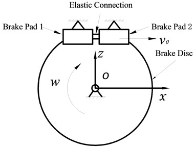
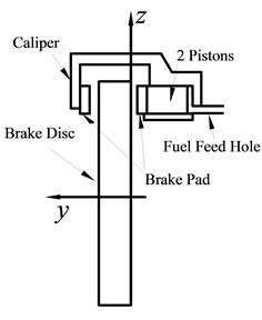
The structure of the dual-cylinder dual-pad brake is schematically depicted in Fig. 1. The disc brake is fixed on the rim and rotates accordingly. The disc brake is regarded as a plate revolving around point o. The two brake pads are fixed on the steering knuckle through brake calipers. The brake pads are elastically connected with each other. The forward direction coordinate xoy is shown in Fig. 1(a), and the side direction coordinate yoz is shown in Fig. 1(b). v0 is the tangential speed of contact point between disc and pad.
Fig. 1Dual-cylinder dual-pad brake
a)
b)
Fig. 2Mechanical model of dual-cylinder dual-pad brake system
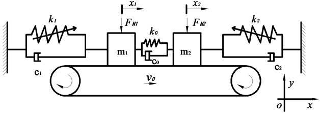
Only the tangential motion of discs and pads is studied in this paper. The brake system in Figs. 1(a) and (b) is simplified into a 2DOF mechanical model illustrated in Fig. 2. The disc brake is regarded as a belt moving with a constant speed v0, and the brake pads are represented by two blocks with m1 and m2 mass. Under the effect of constantly actuating speed v0, the two blocks reciprocate from left to right on the belt. The two blocks are connected with the rigid wall by linear spring with varying stiffness k1, k2 and viscous damper c1, c2. The pressing forces between the two mass blocks and the belt are FN1 and FN2. The two blocks are connected with each other by linear spring k0. The entire system is simplified as a double mass-belt motion.
The differential equations of x direction motion of the system based on Newton’s Second Law are expressed as follows:
where Fi is the dry friction between mass blocks and the belt; Fi=uFNi and i=1, 2 represent the mass block m1 and m2; u is the friction coefficient; FN is the pressing force between mass blocks and the belt; ()'=d()/dt, ()''=d2()/dt2; t is the time.
The stiffness in the aforementioned studies is assumed to be linear; however, the stiffness shows nonlinear effect on system dynamics. This paper focuses on the vibration of the brake pads in the x direction, with the nonlinear stiffness k changing with varying displacement on the x direction. The model [12, 13] of variable stiffness k is expressed as follows:
where ki1 is the linear stiffness coefficient, ki2 is the square stiffness coefficient, and ki3 is the cube stiffness coefficient.
2.2. Selection of brake dry friction model
Dry friction damping force is caused by the absence of lubrication on the interface of two mutually contacting objects, which impedes their relative motion. A sign function is usually used to describe this type of dry friction. The value of dry friction is proportional to the normal pressure between the two contacting objects with its direction opposite to the direction of motion. However, this function describes the physical property of kinetic friction without considering the hysteretic nature of dry friction when the relative velocity is zero. Friction hysteresis is a significant nonlinear behavior mainly displayed as the multi-value and unsmooth nature of friction. This property can generate bifurcation, chaos, and other types of complicated dynamic behavior in the system. Three types of typical hysteresis friction models are currently applied in the brake system.
2.2.1. Bilinear hysteresis model
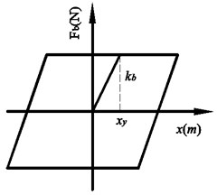
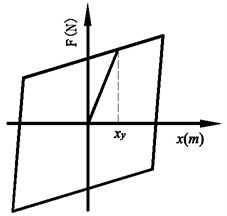
On the basis of ideal dry friction model, Iwan [14, 15] proposed the bilinear hysteresis model in 1961. The formula is expressed as follows:
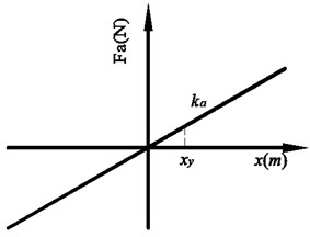
Hysteresis curve can be divided into two parts: hysteresis and elasticity. Fig. 3 indicates the existence of a transitional state when two mutually contacting surfaces change from elastic deformation to slip deformation. The bilinear hysteresis model is only an approximation of the transitional state. The expression of this model is simple and clear, with few physical quantities to identify. The physical meanings are all explicit. However, this model processes the whole state into two linear stiffness matrixes and neglects the influence of the higher order nonlinear stiff system. Moreover, this model cannot describe complicated conditions with the existence of damping.
2.2.2. Mcmillan hysteresis model
In 1997, Mcmillan [16] proposed a new hysteresis dry friction model (Fig. 4). The model divides dry friction into two parts: state dry friction F1 and kinetic dry friction F2. Both are related with relative speed and acceleration on the interface. The mathematical model is expressed as follows:
where:
where μk is the kinetic friction coefficient, μs is the static friction coefficient, v is the relative velocity, and τ is the delay time.
Fig. 3Bilinear hysteresis model
a) Linear part
b) Hysteretic part
c) Linear along with hysteresis
Fig. 4Mcmillan hysteresis model
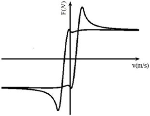
Fig. 5Wojewoda hysteresis model
The Mcmillan hysteresis model can accurately express the effect of hysteresis. However, considerable physical quantities are present in this model, and some even have unclear physical meanings. Parameters are hard to be selected. Meanwhile, the simulation results are remarkable when the value of acceleration x'' is fixed, but unsatisfactory when x'' varies. The acceleration of two contacting surfaces always varies at any time, which limits the calculation of this hysteresis friction model.
2.2.3. Wojewoda hysteresis model
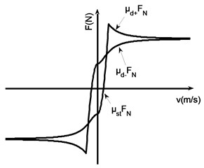
Wojewoda [17, 18] proposed a new friction model to address the deficiency of the previous models (Fig. 5). The mathematical model is expressed as follows:
Among them:
where v=x'-v0 represents the relative velocity, v0 is the initial velocity, uc is the kinetic friction coefficient, us is the static friction coefficient, Δus is the conditioning parameter of maximum static friction, vA is the conditioning parameter of mean velocity, τ is the delay time, and k represents stiffness.
This model introduces transient relative motion acceleration and considers varying static friction nature, maximum static friction nature, Stribeck effect, pre-slip effect, and friction hysteresis to accurately reflect the features of dry friction. Moreover, the formulation of this model is simple and easy to understand and calculate. Hence, this model is selected for further computation and analysis in this paper.
On the basis of Eq. (3) and Table 1, the properties of hysteretic friction are presented in Fig. 6.
Fig. 6Characteristic diagram of hysteretic friction
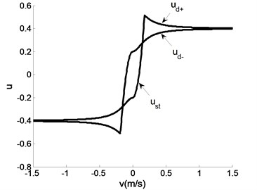
Table 1Parameters for calculation of dry friction properties
Nomenclature | Physical quantities/Unit | Value |
Static friction coefficient | us | 0.6 |
Kinetic friction coefficient | uc | 0.4 |
Delay time | τ/s | 0.002 |
Conditioning parameter of mean velocity | vA | 0.2 |
Conditioning parameter of maximum static friction | Δus | 0.03 |
3. Calculation and analysis of multiple limit cycle properties of system
According to Eqs. (1), (2), (6), and (7), system equations are highly nonlinear. Using analytical methods to solve multiple limit cycle oscillation properties of the system can be difficult; hence, a numerical method is selected. Typical numerical methods include the Euler method, shooting method, and Runge-Kutta method.
The Euler method is the earliest numerical method used to solve the initial value problem of first-order ordinary differential equations. Considering its low calculation accuracy and gross error, the Euler method is seldom used in practical calculation. The shooting method is also a typical method used to calculate nonlinear vibration and is usually applied to solve the response given the period or to solve the period given the response. This method is mainly used in weak linear issues. Given that the dry friction model in this paper is strongly linear, the shooting method is unsuitable to be applied. By contrast, the Runge-Kutta method is widely used because this method can be conveniently employed using Matlab. Considering its ability to make the equation solution smooth enough and to obtain relatively high calculation accuracy, the Runge-Kutta method is used for the numerical calculation in this paper.
3.1. Numerical calculation of multiple limit cycle properties of dual-cylinder dual-pad brake system
With aid from the cooperating brake manufacturer, the dual-cylinder dual-pad brake system is proposed. Subsequently, the dynamic model of the brake system is developed. Wojewoda hysteresis model is selected to search the phenomenon of multiple limit cycles caused by dry friction. The Runge-Kutta method is employed to calculate the multiple limit cycle properties of the proposed brake. The data needed in calculation are listed in Tables 1 and 2.
Table 2System structure parameters
Nomenclature | Physical quantities/Unit | Value | Nomenclature | Physical quantities/Unit | Value |
Mass of brake pad 1 | m1/ kg | 0.5 | Mass of brake pad 2 | m2 / kg | 0.5 |
Linear stiffness coefficient | k11 / N⋅m-1 | 1×10⁶ | Linear stiffness coefficient | k21 / N⋅m-1 | 1×10⁶ |
Square stiffness coefficient | k12 / N⋅m-2 | 1×10⁶ | Square stiffness coefficient | k22 / N⋅m-2 | 1×10⁶ |
Cube stiffness coefficient | k13 / N⋅m-3 | 1×10⁶ | Cube stiffness coefficient | k23 / N⋅m-3 | 1×10⁶ |
Damping | c1 / N⋅m⋅s-1 | 150 | Damping | c2/ N⋅m⋅s-1 | 150 |
Connecting stiffness | k0 / N⋅m-1 | 1×10^4 | Viscous damping | c0 / N⋅m⋅s-1 | 50 |
Brake pressure during braking with varying time is calculated using the selected parameters [19]. The results are illustrated in Fig. 7.
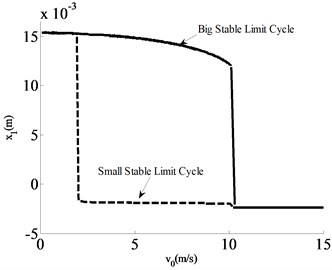
Fig. 7 shows that the brake pressure FN is stabilized in around 6000 N. To calculate system dynamics during braking, FN=6000 N is selected. Considering the symmetry of the two brake pads, only the vibration of the left brake (brake pad 1) is studied. The diagram of displacement of brake pad 1 under different initial excitation and the bifurcation diagram of initial brake speed are shown in Fig. 8.
Fig. 8 shows the bifurcation relationship between the displacement of brake pad 1 and speed under different initial excitation. Brake pad 1 tends to the equilibrium point when initial brake speed v0>10 m/s. With the gradual decrease of initial brake speed, Hopf bifurcation, which generates limit cycles, appears in the system, with the corresponding v0=10 m/s initial brake speed of Hopf. When the initial brake speed 1.8 m/s<v0<10 m/s, weak initial excitation induces small stable limit cycles, and the amplitude of vibration of the brake system is relatively small, and vice versa. When the initial brake speed decreases further until v0<1.8 m/s, the system generates relatively large limit cycles regardless of weak or strong initial excitation, which means that the amplitudes of vibration of the brake system are relatively large.
Fig. 7Diagram of brake pressure varying with time
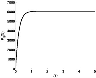
Fig. 8Bifurcation diagram of m1x1-v0 with FN= 6000 N brake pressure
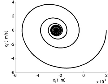
Different initial speeds are determined as v0=12 m/s, 10 m/s, and 1.8 m/s, and the dynamics of brake pad 1 under different initial excitations are calculated (Fig. 9).
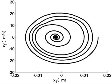
Fig. 9Dynamics of m1 given v0= 12 m/s: a) x1-x1' phase diagram of brake pad 1 under weak initial excitation; b) x1-x1' phase diagram of brake pad 1 under strong initial excitation
a)
b)
Fig. 9 describes the motion dynamics of brake pad 1 under different initial excitations and 12 m/s initial braking speed. The phase diagram of brake pad 1 gradually tends to an equilibrium point without stick-slip motion regardless of strong or weak initial excitation. The final equilibrium point is kept unchanged under different initial excitations.
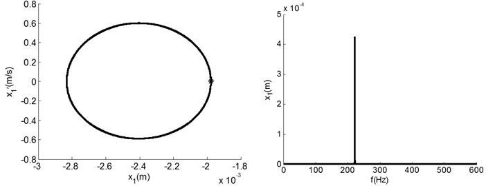
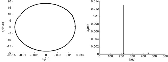
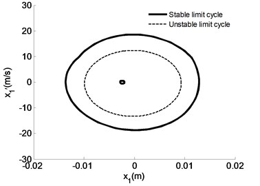
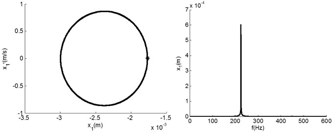
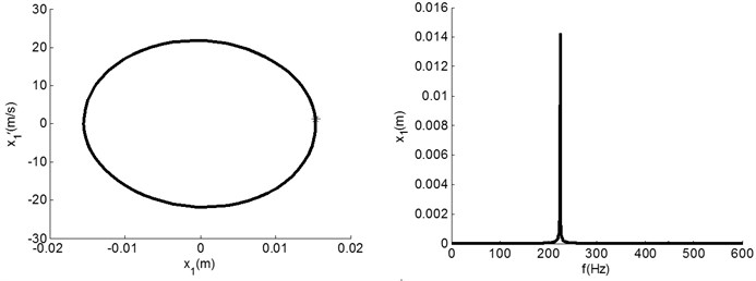
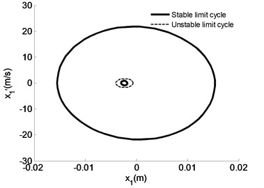
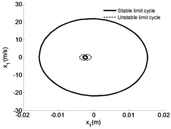
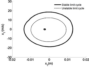
Fig. 10 illustrates the motion dynamics of brake pad 1 under different initial excitations with 10 m/s initial braking speed. When the initial excitation is weak, the phase path of brake pad 1 finally tends to a limit cycle, wherein brake pad 1 obeys a single periodic motion with 0.042 mm amplitude and 223 Hz frequency [Fig. 10(a)]. When the initial excitation is strong, the phase path of brake pad 1 finally tends to a limit cycle, wherein brake pad 1 obeys a single periodic motion with 13.3 mm amplitude and 223 Hz frequency [Fig. 10(b)]. When the initial braking speed is 10 m/s, a small stable limit cycle and a large limit cycle under different initial excitations exist. An unstable limit cycle with 9.6 mm amplitude exists between these two cycles.
Fig. 10Dynamics of m1 given v0= 10 m/s: a) x1-x1' phase diagram, Poincare sections, and FFT spectrogram of brake pad 1 under weak initial excitation; b) x1-x1' phase diagram, Poincare sections, and FFT spectrogram of m1 under strong initial excitation; c) multiple limit cycles of the system
a)
b)
c)
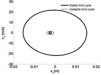
Fig. 11 represents the motion dynamics of brake pad 1 under different initial excitations with 1.8 m/s initial braking speed. When the initial excitation is weak, the phase path of brake pad 1 finally tends to a limit cycle, wherein brake pad 1 obeys a single periodic motion with 6.5 mm amplitude and 223 Hz frequency [Fig. 11(a)]. When the initial excitation is strong, the phase path of brake pad 1 finally tends to a limit cycle, wherein brake pad 1 obeys a single periodic motion with 15.5 mm amplitude and 223 Hz frequency [Fig. 11(b)]. When the initial braking speed is 1.8 m/s, a small stable limit cycle and a large limit cycle under different initial excitations exist. An unstable limit cycle with 1.65 mm amplitude exists between these two cycles.
On the basis of Figs. 8 to 12, the peculiarities of multiple limit cycles of the brake system under different initial speeds are summarized in Table 3.
Based on Figs. 8-11 and Table 3, the conclusions are drawn as follows:
1) The brake frequency of dual-cylinder dual-pad brake is f=220 Hz, which implies oscillation of the braking process. Oscillation occurs when dry friction generates stick-slip motion between brake pads and disc brakes. Oscillation is the phenomenon wherein stable limit cycles appear on the phase diagram.
Fig. 11Dynamics of m1 given v0= 1.8 m/s: a) x1-x1' phase diagram, Poincare sections, and FFT spectrogram of m1 under weak initial excitation; b) x1-x1' phase diagram, Poincare sections, and FFT spectrogram of m1 under strong initial excitation; c) multiple limit cycles of the system
a)
b)
c)
2) Regarding the dual-cylinder dual-pad brake system, the number of its limit cycles changes with varying initial braking speed. A small and a large stable limit cycle exist in the system when the initial braking speed v0 is in the range of 1.8 mm to 10 mm. Moreover, an unstable limit cycle exists between the two stable limit cycles. However, when the initial braking speed v0<1.8 m/s, only the small stable limit cycle exists. The large and the unstable limit cycles disappear. Although the amplitude of the small limit cycle is small, its frequency of vibration is high enough to cause damage to the entire system.
3) The amplitudes of the limit cycles of the dual-cylinder dual-pad brake system also change with varying initial braking speed. With increasing initial braking speed, the amplitude of the large stable limit cycle gradually increases; the amplitude of the small stable limit cycle gradually decreases; and the amplitude of the unstable limit cycle gradually decreases. However, when the initial braking speed is less than a certain value, both the small stable and unstable limit cycles disappear, leaving one large unstable limit cycle.
Table 3Peculiarities of multiple limit cycles of brake system under different initial speeds
Initial brake speed v0 (m/s) | Amplitude of large stable limit cycles (mm) | Amplitude of small stable limit cycles (mm) | Amplitude of unstable limit cycles (mm) |
10 | 13.3 | 0.42 | 9.6 |
1.8 | 15.5 | 0.65 | 1.65 |
3.2. Effects of brake pressure on peculiarities of multiple limit cycles
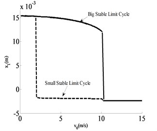
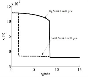
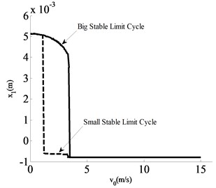
To analyze the effects of brake pressure on the peculiarities of multiple limit cycles, FN=6000 N, FN=5000 N, FN=2000 N are selected for the investigation according to Fig. 7. The obtained system x1-v0 bifurcation diagrams are shown in Figs. 12(a) to 12(c).
Fig. 12x1-v0 bifurcation diagram of m1 under different brake pressure
a)FN=6000 N
b)FN=5000 N
c)FN=2000 N
Fig. 12 presents the bifurcation relationship between the displacements and speeds of brake pad 1 under different initial excitations. This bifurcation diagram is obtained by using Poincare sections method. x'1=0 is used to extract the phase diagram obtaining two corresponding values of x1 and is used to select the larger value to draw the bifurcation diagram. According to Figs. 10 and 11, the large stable limit cycle is symmetric around the vertical axis; hence, the displacement of x1 is extracted and regarded as the approximation of the amplitude. The small limit cycle is not symmetric around the vertical axis but to a point which means the extracted value of x1 is not the true value of the amplitude. However, the variation trend of amplitudes can be reflected on the bifurcation diagram.
Fig. 12 describes the peculiarities of the multiple limit cycles of brake pad 1 under FN=6000 N brake pressure. Hopf bifurcation of braking oscillation in the brake system appears when the initial breaking speed is 10 m/s. Multiple limit cycles appear when the initial braking speed ranges from 1.8 m/s to 10 m/s. The small stable and unstable limit cycles disappear when the initial breaking speed is 1.7 m/s. The maximum amplitude of the large stable limit cycle is 15.7 mm. Moreover, the small stable limit cycle gradually increases with decreasing speed. Hence, the corresponding maximal amplitude of small stable limit cycle appears when the initial braking speed is 1.8 m/s. The unstable limit cycle gradually decreases with decreasing speed. Therefore, the corresponding maximal amplitude of unstable limit appears when the initial breaking speed is 10 m/s.
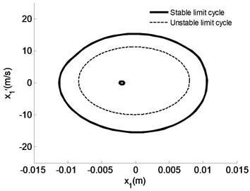
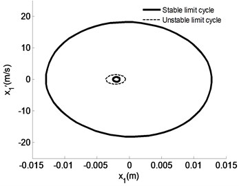
Fig. 12(b) describes the peculiarities of multiple limit cycles of brake pad 1 under FN=5000 N brake pressure. Hopf bifurcation of braking oscillation in the brake system appears when the braking speed is 8.4 m/s. Multiple limit cycles appear when the initial braking speed ranges from 1.6 m/s to 8.4 m/s. The small stable and unstable limit cycles disappear when the initial braking speed is 1.5 m/s. The maximal amplitude of the large stable limit cycle is 13 mm. Furthermore, the corresponding maximal amplitude of the small stable limit cycle appears when the initial braking speed is 1.6 m/s. The maximal amplitude of the unstable limit cycle appears when the initial braking speed is 8.4 m/s.
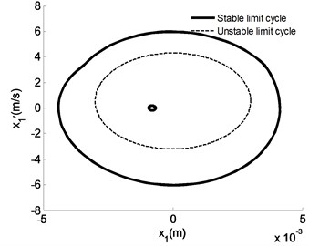
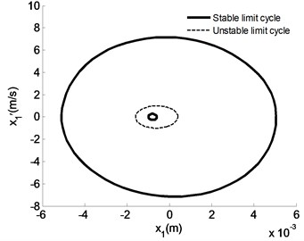
Fig. 12(c) illustrates the peculiarities of multiple limit cycles of brake pad 1 under FN=2000 N brake pressure. Hopf bifurcation of braking oscillation appears in the brake system when the initial braking speed is 3.3 m/s. Multiple limit cycles appear when the initial braking speed ranges from 1.2 m/s to 3.3 m/s. The small stable and unstable limit cycles disappear when the initial braking speed is 1.1 m/s. The maximal amplitude of the large stable limit cycle is 5.1 mm. Moreover, the corresponding maximal amplitude of the small stable limit cycle appears when the initial braking speed is 1.2 m/s. The maximal amplitude of the unstable limit cycle appears when the initial braking speed is 3.3 m/s.
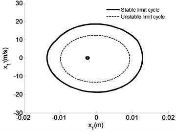
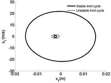
To study the influence of brake pressure on the maximal amplitude of the small stable and unstable limit cycles, according to the aforementioned analysis, (a) FN=6000 N, v0=10 m/s; (b) FN=6000 N, v0=1.8 m/s; (c) FN=5000 N, v0=8.4 m/s; (d) FN=5000 N, v0=1.5 m/s; (e) FN=2000 N, v0=3.3 m/s; and (f) FN=2000 N, v0=1.2 m/s are selected to obtain the diagrams of motion peculiarities of brake pad 1 under different initial excitations.
Fig. 13Motion peculiarities of m1 under different initial speeds given FN= 6000 N
a)v0=10 m/s
b)v0=1.8 m/s
On the basis of the aforementioned analysis and Fig. 12, the amplitude of unstable limit cycle reaches the maximum 9.6 mm when FN=6000 N and v0=10 m/s. In addition, the amplitude of small stable limit cycle reaches its maximum 0.65 mm when v0=1.8 m/s.
The amplitude of unstable limit cycle reaches the maximum 8.2 mm when FN=5000 N and v0=8.4 m/s, and the amplitude of small stable limit cycle reaches its maximum 0.5 mm when v0=1.6 m/s (Fig. 14).
The amplitude of unstable limit cycle reaches the maximum 3 mm when FN=2000 N and v0=3.3 m/s, and the amplitude of small stable limit cycle reaches its maximum 0.2 mm when v0=1.2 m/s (Fig. 15).
On the basis of the aforementioned analysis, we obtain the effects of different pressure on the peculiarities of multiple limit cycles (see Table 4).
Fig. 14Motion peculiarities of m1 under different initial speeds given FN= 5000 N
a)v0=8.4 m/s
b)v0=1.6 m/s
Fig. 15Motion peculiarities of m1 under different initial speeds given FN= 2000 N
a)v0=3.3 m/s
b)v0=1.2 m/s
Table 4Effects of different pressure on peculiarities of multiple limit cycles
Brake pressure FN (N) | Maximal amplitude of large stable limit cycle (mm) | Maximal amplitude of small stable limit cycle (mm) | Maximal amplitude of unstable limit cycle (mm) | Speed range where exist multiple limit cycles (m/s) |
6000 | 15.7 | 0. 65 | 9.6 | [1.8, 10] |
5000 | 13 | 0. 5 | 8.2 | [1.6, 8.4] |
2000 | 5.1 | 0. 2 | 3 | [1.2, 3.3] |
Based on Figs. 12 to 15 and Table 4, the conclusions are drawn as follows:
1) With increasing brake pressure, the maximal amplitudes of large and small stable limit cycles and unstable limit cycles correspondingly increase.
2) With increasing brake pressure, the speed of Hopf bifurcation point increases. Moreover, the corresponding initial speed when the small stable limit cycle and the unstable limit cycle disappear accordingly increases. The speed range where multiple limit cycles exist also increases.
3.3. Effects of combination of kinetic and static friction coefficients on peculiarities of multiple limit cycles.
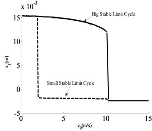
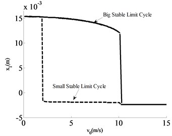
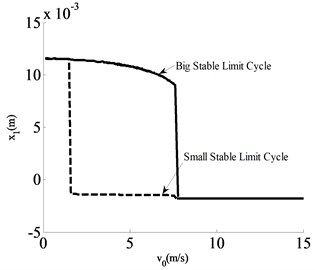
To investigate the effects of friction coefficients on the peculiarities of multiple limit cycles, combinations of different kinetic and static friction coefficients are selected and considered as the research object to obtain different combination of x1-v0 bifurcation diagrams (see Figs. 16(a) to 16(c)).
Fig. 16 describes the peculiarities of multiple limit cycles of brake pad 1 under combinations of different kinetic and static friction coefficients. Figs. 16(a) and 16(b) describe the peculiarities of multiple limit cycles under combinations of uc= 0.4, us=0.6 and uc= 0.4, us=0.8, respectively. The bifurcation characteristics of the two combinations are identical. The initial braking speed when the brake system yields Hopf bifurcation of brake oscillation is 10 m/s. The range of initial braking speed when multiple limit cycles appear is 1.8 m/s to 10 m/s. The initial braking speed when the small stable limit cycle and the unstable limit cycle disappear is 1.7 m/s. The maximal amplitude of the large stable limit cycle is 15.7 mm. The corresponding maximal amplitude of the small stable limit cycle appears when the initial braking speed is 1.8 m/s. The maximal amplitude of the unstable limit cycle appears when the initial braking speed is 10 m/s.
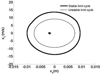
Fig. 16(c) shows the peculiarities of multiple limit cycles for the combination of uc=0.3, us=0.6. The initial braking speed when the brake system yields Hopf bifurcation of brake oscillation is 7.6 m/s. The range of the initial braking speed when multiple limit cycles appear is 1.6 m/s to 7.6 m/s. The initial braking speed when small stable limit cycle and the unstable limit cycle disappear is 1.5 m/s. The maximal amplitude of the large stable limit cycle is 11.5 mm. The corresponding maximal amplitude of the small stable limit cycle appears when the initial braking speed is 1.6 m/s. The maximal amplitude of the unstable limit cycle appears when the initial braking speed is 7.6 m/s.
Fig. 16x1-v0 bifurcation diagrams of m1 displacements under combinations of different kinetic and static friction coefficients
a)uc=0.4, us=0.6
b)uc=0.4, us=0.8
c)uc=0.3, us=0.6
Fig. 17Motion peculiarities of m1 under different initial speeds given uc= 0.4, us= 0.6
a)v0=10 m/s
b)v0=1.8 m/s
Fig. 18Motion peculiarities of m1 under different initial speeds given uc= 0.4, us= 0.8
a)v0=10 m/s
b)v0=1.8 m/s
Fig. 19Motion peculiarities of m1 under different initial speeds given uc= 0.3, us= 0.6
a)v0=7.6 m/s
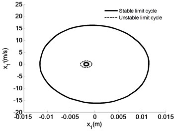
b)v0=1.6 m/s
The corresponding initial braking speeds of the maximal amplitudes of small stable limit cycles and unstable limit cycles under different combinations are selected as follows to study the peculiarities of multiple limit cycles.
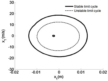
According to the aforementioned analysis and Fig. 17, if uc= 0.4, us=0.6: 1) When v0=10 m/s, the amplitude of unstable limit cycle reaches the maximum value of 9.6 mm; and 2) when v0=1.8 m/s, the amplitude of small stable limit cycle reaches the maximum value of 0.65 mm.
If uc= 0.4, us= 0.8: 1) When v0=10 m/s, the amplitude of unstable limit cycle reaches the maximum value of 9.6 mm; and 2) when v0=1.8 m/s, the amplitude of small stable limit cycle reaches the maximum value of 0.65 mm (Fig. 18).
If uc= 0.3, us=0.45: 1) When v0=7.6 m/s, the amplitude of unstable limit cycle reaches the maximum value of 7.5 mm; and 2) when v0=1.6 m/s, the amplitude of small stable limit cycle reaches the maximum value of 0.45 mm (Fig. 19).
The effects of combinations of different static and kinetic friction coefficients on the peculiarities of multiple limit cycles are summarized in Table 5.
Table 5Effects of combinations of different static and kinetic friction coefficients on peculiarities of multiple limit cycles
Kinetic friction coefficient uc | Static friction coefficient us | Maximal amplitude of large stable limit cycle (mm) | Maximal amplitude of small stable limit cycle (mm) | Maximal amplitude of unstable limit cycle (mm) | Speed range where exist multiple limit cycles (m/s) |
0.4 | 0.6 | 15.7 | 0.65 | 9.6 | [1.8, 10] |
0.4 | 0.8 | 15.7 | 0.65 | 9.6 | [1.8, 10] |
0.3 | 0.6 | 11.5 | 0.45 | 7.5 | [1.6, 7.6] |
Based on Figs. 16-19 and Table 5, the conclusions are drawn as follows:
1) Through comparison of the data between uc= 0.4, us=0.6 and uc= 0.4, us=0.8, the amplitudes of limit cycles and the speed range where multiple limit cycles exist are identical under the same kinetic friction coefficient and different static friction coefficients. This phenomenon verifies that static friction coefficient has few effects on the peculiarities of multiple limit cycles.
2) Through comparison of the data between uc= 0.4, us= 0.6 and uc= 0.3, us=0.6, under the same static friction coefficient and different kinetic friction coefficients, the larger the kinetic friction coefficient is, the larger the amplitudes of limit cycles and speed range where multiple limit cycles appear are. This phenomenon shows the significant influence of kinetic friction coefficients on the peculiarities of limit cycles.
3.4. Effects of mass ratio on peculiarities of multiple limit cycles
Assuming the mass ratio of m1 to m2 to be δ, given v0=6 m/s, the obtained x1-δ bifurcation diagram is shown in Fig. 20.
Fig. 20 illustrates the peculiarities of multiple limit cycles of brake pad 1 with different mass ratio. The amplitude of the large stable limit cycle progressively increases with increasing mass ratio [Fig. 20(a)]. The amplitude of small stable limit cycle initially increases and then decreases with increasing mass ratio and the amplitude reaches maximum value when δ=1 [Fig. 20(b)].
Fig. 20x1-δ bifurcation diagram of the displacements of m1 given v0= 6 m/s
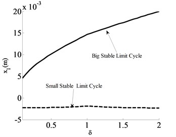
a) Global diagram
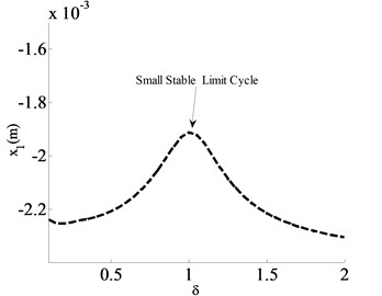
b) Diagram of partially enlarged details
4. Conclusions
1) With aid from the cooperating brake manufacturer, a floating caliper-based dual-cylinder dual-pad brake system is proposed. The dynamic model of the system is developed incorporating Wojewoda hysteresis dry friction model. Results showed that the system suffer from multiple limit cycle oscillation over a certain range of braking speed. Its phase diagram presents a stable limit cycle with a large amplitude, a stable limit cycle with a small amplitude, and a phenomenon of an unstable limit cycle between two cycles.
2) With decreasing initial braking speed v0, the amplitudes of large and small stable limit cycles increase, and the amplitude of the unstable limit cycle decreases. When the initial braking speed v0 is below a certain value, both the unstable limit cycle and the small limit cycle disappear.
3) With increasing brake pressure, the maximum amplitudes of the large stable limit cycle, the small stable limit cycle, and the unstable limit cycle correspondingly increase. The speeds of disappearance for the small stable limit cycle and the unstable limit cycle accordingly increase. In addition, the speed range of multiple limit cycles increases.
4) The larger the kinetic friction coefficient is, the larger the amplitudes of multiple limit cycles and the speed range where multiple limit cycles exist are. On the contrary, the static friction coefficients have no significant effect on the peculiarities of multiple limit cycles.
5) With increasing mass ratio of m1 to m2, the amplitude of the large stable limit cycle increases by degrees, whereas the amplitude of the small stable limit cycle initially increases then decreases.
References
-
ShinK., Brennan M. J. Analysis of disc brake noise using a two-degree-of-freedom model. Journal of Sound and Vibration, Vol. 254, 2002, p. 837-848.
-
Shin K., Oh J. E., Brennan M. J. Nonlinear analysis of friction induced vibrations of a two-degree-of-freedom model. JSME International Journal, Vol. 42, Issue 2, 2002, p. 426-432.
-
Wei Shi Study of Hopf Bifurcation Effect on Automotive Brake System Induced By Dry Friction. Hefei University of Technology, Hefei, 2014.
-
Donley M. G. Brake groan simulation for McPherson strut-type suspension. SAE Technical Papers, Vol. 43, 2009, p. 16-27.
-
Paliwal Manish, Mahajan Ajay, Don Jarlen Noise and vibration analysis of a disc-brake system using a stick-slip friction model involving coupling stiffness. Journal of Sound and Vibration, Vol. 282, 2005, p. 1273-1284.
-
Hetzler H., Schwarzer D., Seemann W. Analytical investigation of steady-state stability and Hopf-bifurcations occurring in sliding friction oscillators with application to low-frequency disc brake noise. Communications in Nonlinear Science and Numerical Simulation, Vol. 12, 2007, p. 83-99.
-
Nosrati Ali, Farshidianfar Anoushiravan Analytical approximations for stick-slip vibration amplitudes based on a discretization method. 16th International Congress on Sound and Vibration, Vol. 26, 2009, p. 1-8.
-
Yang F. H., Zhang W., Wang J. Sliding bifurcations and chaos induced by dry friction in a braking system. Chaos, Solutions and Fractals, 40, 2009, p. 1060-1075.
-
Ouyang H., Mottershead J. E., Cartmell M. P., Brookfield D. J. Friction-induced vibration of an elastic slider on a vibrating disc. International Journal of Mechanical Sciences, Vol. 41, 1999, p. 325-336.
-
Yang Fenghong, Zhang Wei Nonlinear dynamic analysis for a disc braking system. Journal of Vibration and Shock, Vol. 28, 2009, p. 93-99.
-
Meng Xianjie, Wu Guangqiang Numerical solution for vibration behavior of automotive brake disc and pads. Journal of Jiangsu University, Vol. 32, 2011, p. 292-296.
-
Sinou J. J., Thouverez F., Jezequel L. Center manifold and multivariable approximants applied to non-linear stability analysis. International Journal of Non-Linear Mechanics, Vol. 38, 2003, p. 1421-1442.
-
Sinou J. J., Thouverez F., Jezequel L. Analysis of friction and instability by the center manifold theory for a non-nilear sprag-slip model. Journal of Sound and Vibration, Vol. 265, 2003, p. 527-559.
-
Iwan W. D. The Dynamics Response of Bilinear Gysteretic System. California Institute of Technology, California, 1961.
-
Oden J. T., Martins J. A. C. Models and computational methods for dynamic friction phenomena. Computer Methods in Applied Mechanics and Engineering, Vol. 52, Issues 1-3, 1985, p. 527-634.
-
McMillan A. J. A non-linear friction model for self-excited vibration. Journal of Sound and Vibration, Vol. 205, Issue 3, 1997, p. 323-335.
-
Wojewoda Jerzy, Stefanski Andrzej, Wiercigroch Marian, Kapitaniak Tomasz Hysteretic effects of dry friction: modeling and experimental studies. Mathematic Physical and Engineering Science, Vol. 366, 2008, p. 747-765.
-
Stefanski A., Wojewoda J., Wiercigroch M., Kapitaniak T. Regular and chaotic oscillations of friction force. Proceedings of the Institution of Mechanical Engineers, Part C: Journal of Mechanical Engineering Science, Vol. 220, Issue 2, 2006, p. 273-284.
-
Haifu Su Thermal-Mechanical Coupled Finite Element Analysis on Disc Brake. South China University of Technology, Guangzhou, 2011.
About this article
This project is supported by National Natural Science Foundation of China (Grant Nos. 51375130, 51050002).
