Abstract
The main objective of this paper is to develop active control mechanism based on fuzzy logic controller (FLC) for improving vehicle path following, roll and handling performances simultaneously. At the first stage, 3DOF vehicle model which includes yaw rate, lateral velocity (lateral dynamic) and roll angle (roll dynamic) are developed. The controller produces optimal moment to increase stability and roll margin of vehicle by receiving the steering angle as an input and vehicle variables as a feedback signal. The effectiveness of proposed controller and vehicle model are evaluated during fishhook and single lane-change maneuvers. Simulation results demonstrate that FLC by reducing roll angle, lateral velocity and acceleration, vehicle roll resistance and handling properties are improved. Finally the sensitivity and robustness analysis of developed controller for varying longitudinal speeds are investigated.
1. Introduction
There are two perspectives for handling ratings. One perspective is how safe the vehicle is to drive. The other is how well the vehicle gives an enthusiast driver a pleasurable sense of control. Suspension system and its components (stiffness and damping rates) have significant role in vehicle motion and handling properties. Coil springs which usually are used in passenger vehicle suspension system are less stiff with better ride comfort compared to leaf springs. Therefore, the roll stiffness of the vehicle with coil springs is usually less than in vehicles with leaf springs. In order to improve the roll characteristic of coil springs an antiroll bar mechanism must be used (Fig. 1).
Fig. 1Anti-roll bar system in passenger car suspension [1]
![Anti-roll bar system in passenger car suspension [1]](https://static-01.extrica.com/articles/16054/16054-img1.jpg)
Various mechanisms such as optimal geometry passive [2], semi active [3], active [4] suspensions and anti-roll bar [5] systems have been studied to compromise the trade-offs between ride and handling. Due to active suspension systems cost, energy usage and packaging difficulties, they are used on a limited basis for Luxury and special vehicles. Whilst, anti-roll bar recently has become practical solution to improve vehicle handling, roll-stability and ride comfort. Also, active control systems such as DYC, AFS, and VDC are developed in previous researches to improve vehicle stability and roll resistance [6-10]. Papelis et al. [7] utilized Electronic stability control (ESC) to assist driver in maintain vehicle control and prevention of vehicle loss of control. Their results showed that using ESC 25 % reduces loss of control in severe maneuvers.
Previous researches studied the mechanism and systems for prevention of rollover while ensuring not to satisfy handling and ride properties. In [8] a novel FLC is proposed to improve vehicle safety by regulating dampers in semi active suspension system. The controller stabilize the sprung mass which improves vehicle handling and reduces possibility of overturning. Singh and Darus [9] presented an active roll control system using an active suspension based on fuzzy logic control for enhancement of vehicle roll dynamics. Mashadi et al. [10] developed a DYC system based on LQR, for vehicle path following with considering the driver performance. They used 2 DOF vehicle model for developing of LQR controller. Their results showed that LQR controller could be properly applied for vehicle path following and improving handling characteristic. They tried to maintain the lateral acceleration and velocity under 0.8 m/s2 and 40 m/s respectively.
In previous studies various control strategies are utilized to control vehicle path control, improving ride, handling and rolling resistance systems [11-17]. Wu et al. [11] developed a robust chassis controller to improve vehicle handling performance and lane keep ability by utilizing H∞ controller. Wang et al. [14] used fuzzy inference engines to design steering controller and determine the given driving speed for autonomous vehicle. Mashadi et al. [10, 12] proposed an optimal LQR and PID controllers for vehicle path following based on intelligent optimization method. They utilized genetic algorithm procedure to adapt a set of optimized controller parameters suitable for various driving styles, road conditions and the initial errors of vehicle position and orientation.
A unified chassis control proposed in [18] to prevent vehicle rollover, and to improve vehicle maneuverability and its lateral stability by integrating electronic stability control (ESC) and active front steering (AFS). The rollover prevention was achieved through speed control, and the vehicle stability is improved via yaw rate control. Cao et al. [19] proposed the integrated controller of the yaw and rollover stability controls using nonlinear prediction model. The linearization tire model was built up as the rollover predictive model and its accuracy obtained by real vehicle tests. These researches were focused on improving handling, ride or rollover resistance separately by active control systems. Whilst in this paper a tradeoff between handling properties and rollover resistance compromised through anti roll bar moment system which is controlled based on FLC. The proposed control structures are typically based on combination of the steer angle, roll angle, longitudinal speed, yaw and roll moments, lateral acceleration and velocity, which controls the yaw rate and the roll motion simultaneously.
2. Vehicle model
In order to investigate the roll over resistance and handling behavior of vehicle simultaneously, integrated lateral and roll dynamics should be considered. So, in this paper two vehicle model is utilized. At the first, a 3 DOF roll model for controller designing is developed which its degrees includes: lateral velocity, yaw and roll. In addition to realize the simulating of the vehicle model, a comprehensive vehicle model (an 8 DOF model) in [10] is utilized to simulation.
2.1. An 8 DOF model
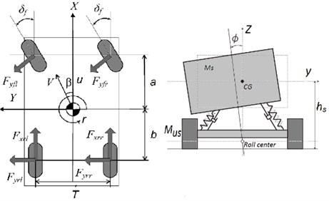
In this article, to simulate the control of a vehicle during roll tests, as demonstrated in Fig. 2, a non-linear 8-DOF is used. The DOFs associated with this model are the longitudinal velocity u, the lateral velocity v, the yaw rate r, the roll Φ, and four wheel rotational speeds, ωfl, ωfr, ωrl and ωrr:
+T2[(Fxfl+Fxrl)-(Fxfr+Fxrr)]+∑4i=1Mzi,
Fig. 2Vehicle 8 DOF including roll, yaw and longitudinal model
2.2. Vehicle roll model
In order to evaluate the roll behavior of vehicle during sever maneuvers, the main parameters which effects on vehicle roll stability should be considered such as: variation of center of gravity, vehicle track, tire and suspension properties. In this paper as shown in Fig. 3, a 3 DOF vehicle model which combines 2 DOD bicycle model (r and v) with 1 DOF roll model (Φ) is developed.
Fig. 3Vehicle 3 DOF model (yaw and roll)
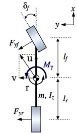
a) 2DOF bicycle model
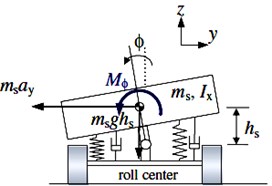
b) 1DOF roll model
By imposing Newton’s second law of motion along the y-axis and the torque balance around the z-axis and x-axis, the equation of motion for lateral, yaw and roll dynamic can be expressed respectively as:
where ay, r and Φ lateral acceleration, yaw rate and roll angle respectively. MΦ and ms are sprung and roll mass respectively, and hs is the distance between central of gravity to roll center of sprung mass. Also, Fyf and Fyr are lateral forces of front and rear tires respectively. Kϕ and Cϕ are Roll stiffness and Roll damping coefficients of suspension system which are calculated through damping (Cs), springs (Ks) and anti-roll bar (KARB) stiffness of rear and front axels:
2.3. Load transfer
If the vehicle body rolls, the left and right wheels at both front and rear axles will increase in load at one side and decrease at the other side. This is called the load transfer due to roll. Defining the load transfer for the axle load ∆; the roll moment around the roll center at the wheels in the plane perpendicular to the vehicle longitudinal direction has to be in equilibrium, as shown in Fig. 3, the following equations are derived:
These equations give the load transfer between the left and right wheels due to a constant lateral acceleration. The equations show that a higher vehicle center of gravity distance from the roll axis, hs, results in a larger load transfer at the front and rear wheels. Furthermore, a load transfer at the front and rear wheels is basically proportional to the front and rear roll stiffness ratios to the total roll stiffness, respectively.
The original rollover resistance ratings were determined solely from the vehicle’s static stability factor. The SSF of a vehicle is a calculation of rollover resistance, based on its most important geometric properties. As shown in Fig. 3, vehicle’s SSF is calculated taking the moments about the center of contact for the outside tires yields:
The lower the SSF number, the more likely the vehicle is to roll over in a tripped single-vehicle crash. A higher SSF value equates to a more stable, less top-heavy vehicle.
3. Controller design
In this study, two types of controller are developed, one based on FLC for nonlinear vehicle model and the other is based on linear quadratic regulation for linear vehicle roll model. In both cases front steering angle and momentum deduced by controller for prevention of increasing roll angle are defined as system inputs. State variables include lateral velocity, yaw rate, roll angle and roll rate as:
By considering 3 DoF vehicle model in previous section, state space for designing controller described as:
Since the main objective of this study is to reduce roll angle or increase rollover threshold (stability), so controller should regulates the lateral load transfer (LLT) in its optimal condition. LLT criteria as a function of lateral acceleration, roll and roll rate is obtained as:
When one of the tires losses its contact with road and applied force on tire eliminates, rollover occurs. In this condition, LLT becomes 1 and rollover happens. In other words, when the forces at the both sides are equal, LLT becomes zero and vehicle is in most stable condition.
3.1. Fuzzy controller development
Owing to its simple practical nature, Fuzzy type controllers shown in Fig. 4 are developed for roll resistance of the vehicle model. This type of controllers has the advantages of using expert’s attitude and experimental results. The anti-roll moment control law for the desired state space vector is achieved by this control system.
Fig. 4The FLC structure

In this paper, control strategy is developed by FLC, applying Mamdani implication (Fig. 5). The main objective of this controller is to maintain vehicle stability and prevention of vehicle rollover during maneuvers.
Three steps are taken to create a fuzzy controlled system [20]:
– Fuzzification: Using membership functions to graphically describe a situation (Fuzzification is the process of changing a real scalar value into a fuzzy value).
– Rule evaluation: Application of fuzzy rules (The rules are composed of a set of if–then rules, from which an inference mechanism is formed).
– Defuzzification: Obtaining the crisp or actual results (The centroid defuzzification technique is utilized in this paper to defuzzify set to get a numerical output as the control signal).
In this paper FLC applying Mamadani implication and based on state variables and control parameters, three condition are considered for fuzzification which demonstrate the status of control strategy parameters; low, normal, and high. The rules are composed of a set of if-then rules, from which an inference mechanism is formed. In other words rules describe the relation between state variable and control parameters.
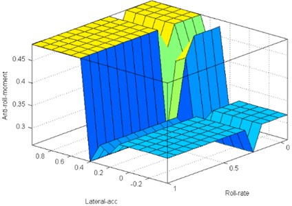
As shown in Fig. 4 a FLC is developed to design a control strategy, which has two state variables as inputs (roll rate and lateral acceleration) and one control parameter as an output (Anti-roll moment). The antiroll-bar controller is modeled in the FLC and their membership functions of the inputs and outputs are shown in the figure 5.
The designed FLC has 2 inputs, 3 MFs for each input and 9 fuzzy rules for each input. Requested anti roll moment is normalized so that the number 0.5 allocated to optimum moment. Therefore, the center of MFs are located in 0.5. Also, as shown in Fig. 5, rules are set to respect the rules overlap. The surface of them are shown in the figure 6. Rules based on vehicle roll model are regulated whenever, lateral acceleration and roll-rate of vehicle is increased, controller commands anti-roll bar system to produce more moment to improve vehicle handling properties and prevention of rollover.
Fig. 5Membership functions of the two modes in the FLC
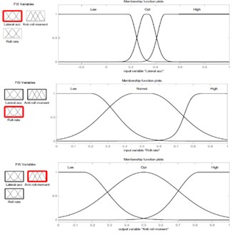
Fig. 6The two modes rules surface
4. Simulation results
To evaluate the vehicle roll and handling dynamic behavior and the effectiveness of anti-roll bar over Fishhook maneuver, numerical evaluation are conducted using MATLAB/SIMULINK environment. This simulation code is validated and used extensively of [10]. Steering angle as an input signal to vehicle closed loop model in fishhook maneuver is illustrated in Fig. 7.
Vehicle path following (path, lateral deviation), roll (load transfer, roll rate, roll and lateral acceleration), handling performance (side slip, lateral velocity and acceleration) and control effort (roll moment) at constant speed over Fishhook maneuver are presented in three cases (Figs. 8-15 respectively); FLC (120 km/hr), without control at 90 km/hr and 120 km/hr.
Vehicle path following and deviation of desired path, demonstrate that controller can properly control the vehicle dynamic variables to track driver intended path with minimize deviation. Also, as shown in Figs. 8 and 9, increasing longitudinal velocity during fishhook maneuver results in more deviation of vehicle from track.
Fig. 7Steering angle in fishhook maneuver
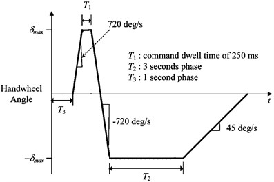
Fig. 8Fishhook maneuver path
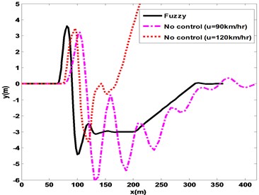
Fig. 9Lateral deviation in fishhook maneuver
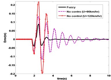
Fig. 10Roll angle in fishhook
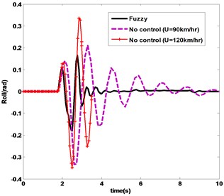
Fig. 11Roll rate in fishhook
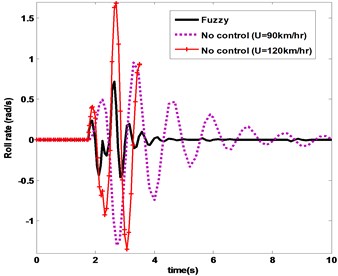
Simulation results of vehicle roll variables includes roll angle, roll rate, load transfer and controller moment over fishhook maneuver are depicted in Figs. 10-13 respectively. FLC has the minimum amount and oscillations of control effort and roll responses. Also, it is obvious that in without control cases, vehicle tends to rollover and with increasing the vehicle longitudinal speed from 90 km/hr to 120 km/hr turning over occurs at 3.8 second.
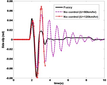
Furthermore, from the handling properties includes lateral acceleration of Fig. 14 and side slip angle of Fig. 15 it can be concluded that the both controllers achieves the optimal handling conditions. In controlled cases, lateral acceleration and side slip angles remain under 0.6 g and 4 degree during maneuver, which ensures vehicle stability and handling properties.
Fig. 14Lateral acceleration in fishhook
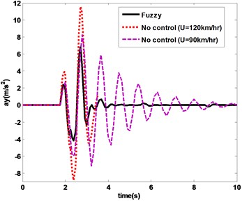
Fig. 15Side slip angle in fishhook
5. Conclusion
In this study, the effectiveness of anti-roll bar mechanism was investigated for improving vehicle, stability, roll resistance, path following and handling properties. For this purpose FLC theory based on vehicle 3 DOF roll dynamic are developed to produce optimal momentum. Controller are trained to follow desired side slip, roll angle, and yaw rates during various fishhook maneuvers. An 8 DOF vehicle model in MATLAB/Simulink environment is utilized to simulate the controller performance and vehicle behavior. Simulation results clarified that, control strategy hold the lateral acceleration and side slip angles less than limited critical overturning and instability for various speeds and maneuvers. Moreover, the FLC roll and handling controller showed better results, with smaller control effort, roll and side slip angles in severe maneuvers. Finally, in regard to that in quick emergency maneuvers, vehicle has a greater likelihood to roll over, the sensitivity analysis of FLC to longitudinal speed is conducted. It showed that proposed controller could be more effective in high speed, which prevents the vehicle overturning in quick maneuvers.
References
-
http://www.carbibles.com/images/antiroll, 2015.
-
Mahmoodi-Kaleibar M., Javanshir I., Asadi K., Afkar A., Paykani A. Optimization of suspension system of off-road vehicle for vehicle performance improvemen. Journal of Central South University, Vol. 20, 2013, p. 902-910.
-
Savaresi S. M., Poussot-Vassal C., Spelta C., Sename O., Dugard L. Classical Control for Semi-Active Suspension System, Semi-Active Suspension Control Design for Vehicles. Chapter 6. Butterworth Heinemann, Italy, 2010.
-
Huang Y., Na J., Wu X., Liu X., Guo Y. Adaptive control of nonlinear uncertain active suspension systems with prescribed performance. ISA Transactions, Vol. 54, 2015, p. 145-155.
-
Zulkarnain N., Imaduddin F., Zamzuri H., Mazlan S. Application of an active anti-roll bar system for enhancing vehicle ride and handling. 2012 IEEE Colloquium on Humanities, Science and Engineering Research, Sabah, Malaysia, 2012, p. 260-265.
-
Cronje P. H., Els P. S. Improving off-road vehicle handling using an active anti-roll bar. Journal of Terramechanics, Vol. 47, 2010, p. 179-189.
-
Papelis Y. E., Watson G. S., Brown T. L. An empirical study of the effectiveness of electronic stability control system in reducing loss of vehicle control. Accident Analysis and Prevention, Vol. 42, 2010, p. 929-934.
-
Biglarbegian M., Melek W., Golnaraghi F. Design of a novel fuzzy controller to enhance the stability of vehicles. IEEE Proceedings of NAFIPS Conference, San Diego, CA, 2007.
-
Singh A., Singh P., Zaurah I., Darus M. Active roll control strategy using fuzzy logic control active suspension. WSEAS Transactions on Systems and Control, Vol. 9, 2014, p. 566-573.
-
Mashadi B., Mahmoodi-k M., Kakaee A. H., Hoseini R. Vehicle path following control in the presence of driver inputs. Proceedings of the Institution of Mechanical Engineers, Part K: Journal of Multi-body Dynamics, Vol. 227, 2013, p. 115-132.
-
Wu J., Wang Q., Wei X., Tang H. Studies on improving vehicle handling and lane keeping performance of closed-loop driver-vehicle system with integrated chassis control. Mathematics and Computers in Simulation, Vol. 80, 2010, p. 2297-2308.
-
Mashadi B., Mahmoodi-k M., Ahmadizadeh P., Oveisi A. A path-following driver/vehicle model with optimized lateral dynamic controller. Latin American Journal of Solid and Structures, Vol. 11, 2014, p. 613-630.
-
Tafner R., Reichhartinger M., Horn M. Robust online roll dynamics identification of a vehicle using sliding mode concepts. Control Engineering Practice, Vol. 29, 2014, p. 235-246.
-
Wang X., Fu M., Ma H., Yang Y. Lateral control of autonomous vehicles based on fuzzy logic. Control Engineering Practice, Vol. 34, 2015, p. 1-17.
-
Shyrokau B., Wang D., Savitski D., Hoepping K., Ivanov V. Vehicle motion control with subsystem prioritization. Mechatronics, In Press, 2014.
-
Zhao H., Gao B., Ren B., Chen H. Integrated control of in-wheel motor electric vehicles using a triple-step nonlinear method. Journal of the Franklin Institute, Vol. 352, 2015, p. 519-540.
-
Eteffagh M. M., Behkamkia D., Pedrammehr S., Asadi K. Reliability analysis of bridge dynamic response in a stochastic vehicle-bridge interaction. KSCE Journal of Civil Engineering, Vol. 19, 2014, p. 220-232.
-
Yoon J., Cho W., Kang J., Koo B., Yi K. Design and evaluation of a unified chassis control system for rollover prevention and vehicle stability improvement on a virtual test track. Control Engineering Practice, Vol. 18, 2010, p. 585-597.
-
Cao J., Jing L., Guo K., Yu F. Study on integrated control of vehicle yaw and rollover stability using nonlinear prediction model. Hindawi Publishing Corporation Mathematical Problems in Engineering, 2013, p. 643548.
-
Montazeri-Gh M., Mahmoodi-k M. Development a new power management strategy for power split hybrid electric vehicles. Transportation Research Part D, Vol. 37, 2015, p. 79-96.
