Abstract
For the universal phenomenon of the aero-engine connectors with the looseness fault, a single degree of freedom lumped mass model was established and a looseness fault model was introduced. The response of the system was obtained by numerical integration methods and the asynchronous response characteristics were analyzed. The experiments were conducted on the connectors with looseness clearance. It is found that the acceleration response of the mass block after noise reduction has up-down asymmetrical impact characteristics in the waveform, also the pseudo-critical subharmonic resonance and the pseudo-critical ultra-harmonic resonance appear in frequency spectrum. These characteristics are in agreement with the results of the numerical simulation, which can be identified as the characteristics of the looseness fault. The reason leading to the looseness characteristics is that the period of stiffness changes in the period of the rotating speed. When the changing period of stiffness is equivalent to the vibration period, frequency multiplication will appear and the natural frequency of the system will be excited at specific speeds. When the changing period of stiffness is equivalent to n times the vibration period, 1/n frequency division and frequency multiplication will appear and the natural frequency of the system will be excited at specific speeds.
1. Introduction
The looseness fault, caused by low installation quality or long-term vibration, is a universal phenomenon in high-speed rotating machinery including the aero-engine. When looseness fault exists in rotor-support-casing system, rotor will be lifted up periodically if the unbalanced force is greater than the gravitational force, and this will cause severe vibration. Serious looseness fault may lead to rub-impact fault between rotor and stator. Therefore, effective identifying the looseness fault is of great significance. For the phenomenon of the pseudo-critical subharmonic resonance and the pseudo-critical ultra-harmonic resonance caused by the looseness fault, studying its mechanism is of great significance for better understanding the essence of the looseness fault.
Many scholars have carried out a few works on the looseness fault. Fredric F. Ehrich [1] used a simple numerical model of a rotor employing a piecewise linear (that is, a bilinear) bearing support stiffness to represent the system, it was possible to replicate the new class of asynchronous rotor dynamic response in high-speed rotors over a range of sub-, trans-, and supercritical high-speed rotor operation. Muszynska et al. [2] established a rotor-bearing-stator model with a one-lateral-mode unbalanced, bearing looseness and rotor-stator rubbing, showing the nonlinear characteristics of the periodic vibrations of synchronous (1×), sub-synchronous (1/2×, 1/3×…) and multiples (2×, 3× …). Chen et al. [3] adopted a new method to study the sub / super harmonic resonance of nonlinear system with single degree of freedom and sub-harmonic solution of a piecewise linear oscillator with two degrees of freedom. Chu [4] investigated the vibration characteristics of a rotor-bearing system with pedestal looseness, used shooting method to obtain the periodic solutions, and analyzed the steady of the periodic solutions by the Floquet theory. Chen [5] established an unbalance-rubbing coupling faults dynamical model with rolling bearing-rotor system, and obtained the nonlinear dynamic response laws of rotor-ball bearing-stator system under unbalance and rubbing coupling fault. Ma [6] established the finite element model of a rotor system with pedestal looseness stemming from a loosened bolt, and the effects of the looseness parameters on its dynamic characteristics were analyzed. Goldman et al. [7] developed an analytical algorithm for investigating local non-linear effects in rotor systems. They used a specially developed variable transformation that smoothes discontinuities, and then they applied an averaging technique. Their results showed good agreement with experimentally observed typical behaviors and orbits of rubbing rotors. In the last two papers, the effects of pedestal looseness on the system response were also studied. Lu and Chu [8] studied the looseness fault of rotor system by experiments. The characteristics of multiple frequency and frequency division were found. Ji and Zu [9] analyzed the free and forced vibration of a non-linear bearing system to illustrate the non-linear effect on the free and forced vibrations of the system by the method of multiple scales. Behzad and Asayeshthe [10] proposed a finite element method for studying the effects of loose rotating disks on the rotor-bearing systems’ response.
At present, there are few works on support looseness fault in aero-engine and many works are not studied fully. Due to low bearing stiffness in aero-engine, the wide use of thin-walled structure in rotor and casing and its great flexibility, looseness phenomenon is universal. An unforeseen array of asynchronous response frequencies at other than the critical were noted when the aero-engine was operated at both subcritical and supercritical speeds. Those responses were not explored in detail at this time. To better understand the essence of looseness fault, the analysis of asynchronous response characteristics is of great significance.
In order to study the mechanism of pseudo-critical sub-harmonic resonance and pseudo-critical ultra-harmonic resonance caused by the looseness fault, firstly, a model of foundation vibration was established, which was used to simulate a single disk mounted on a massless shaft, and the looseness fault model was introduced. The response of mass block was obtained by numerical integration method and the asynchronous response characteristics were analyzed. Literature [1] only provides the phenomenon of frequency division and frequency multiplication. However, the reason of this phenomenon was not be discussed. Secondly, the experiments on the connectors with looseness clearance were conducted. It is found that the acceleration response of the mass block after noise reduction has up-down asymmetrical impact characteristics in the waveform, and the pseudo-critical subharmonic resonance and the pseudo-critical ultra-harmonic resonance appear in frequency spectrum. These characteristics are in agreement with the results of the numerical simulation, which can be used to judge the looseness fault. By comparing the results of the simulation with the experimental results, it can reveal the asynchronous response law of looseness fault.
2. A single degree of freedom lumped mass model with looseness fault
2.1. A single disk-rotor model
The differential equations of the unbalance response of a single disk mounted on a massless shaft can be described as follows:
where u and v are the displacements of the rotor, m is the mass of the disk, c is the viscous damping, k is the transverse stiffness of the shaft, e is eccentricity, and ω is rotational speed of the rotor.
2.2. A foundation looseness model
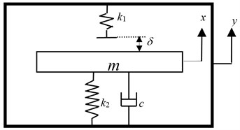
In order to study the mechanism of the looseness fault between component and foundation, a simple mass-spring model with looseness fault is established, and the mass block is always connected with the foundation, as shown in Fig. 1.
It is assumed that the mass of mass block is m, the contact stiffness between the mass block and the foundation is k2, the damping is c, the contact stiffness between the mass block and the hard spring is k1; the looseness clearance is δ, the vibration displacement of the mass block is x, and the vibration displacement of the foundation is y.
The differential equation of the mass block under the foundation vibration can be described as follows:
Fig. 1Mass and foundation looseness model sketch
The contact stiffness between the mass block and the foundation under the conditions of different relative displacements can be described as follows:
It is assumed that vibration frequency of the foundation is f, the amplitude is A, the vibration displacement of the foundation y=Asin(2πft), and the relative displacement between the mass block and the foundation z=x-y. The relative motion equation can be described as follows:
Since the second formula of Eq. (1) is similar to Eq. (4), and the looseness fault has directivity, which means the vibration in x direction and in y direction are separable, Eq. (4) can be used to simulate the looseness fault of single disk-rotor model. The relative displacement z can be used to simulate the displacement of rotor and the relative acceleration ¨z can be used to simulate the acceleration of rotor.
Then, the natural frequency of the hard spring f1=((k1+k2)/m)1/2 and the natural frequency of the soft spring f2=(k2/m)1/2. It is assumed that the natural frequency of the system is fn; the clearance δ is smaller, the vibration time is very short, and it can be ignored, so that the vibration period of this system is half of the sum of the vibration period of the hard spring and the soft spring, it can be described as follows:
2.3. Simulation analysis of looseness fault
For studying the strong nonlinear characteristics caused by the looseness fault, smaller damping and larger stiffness are adopted. It is assumed that the mass of the mass block m= 10 kg, the vibration amplitude of the foundation A= 100 µm, the damping between the mass block and the foundation c= 20 N·s/m, the contact stiffness k2= 9.85×10⁵ N/m, and the contact stiffness k1 between the mass block and the hard spring is 100k2. The natural frequency of this system, according to the Eq. (5), fn= 90.9 Hz. The response of this system is solved by the improved Newmark-β algorithm [13]. When the hard spring is contacted, the contact condition is marked 1, otherwise the contact condition is marked 0.
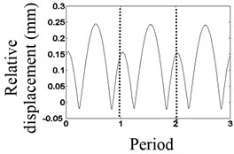
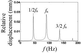
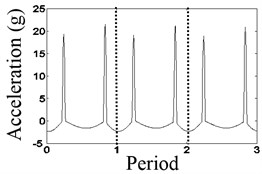
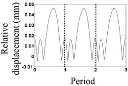
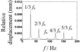
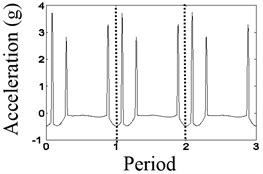
The results are shown in Figs. 2, 3, when the vibration frequencies are 1/2fn and 1/3fn, respectively. In Fig. 2(a), the waveform of relative displacement has two bounces and two peaks per revolution. In Fig. 2(b), the rotational frequency and the larger double frequency appear in the spectrum of the relative displacement. In Fig. 2(c), the acceleration of the mass block has two bounces per rotation. In Fig. 3(a), the waveform of the relative displacement has three bounces and three peaks per revolution. In Fig. 3(b), the rotational frequency, the larger double frequency and the natural frequency of the system appear in the spectrum of the relative displacement. In Fig. 3(c), the acceleration of the mass block has three bounces per rotation. As shown in Figs. 2(c), 3(c), the changing period of stiffness is equivalent to the period of the rotating speed, so that frequency multiplication components appear.
Fig. 2Waveform characteristics at 1/2 times the natural frequency
a) Waveform
b) Spectrum
c) Waveform
Fig. 3Waveform characteristics at 1/3 times the natural frequency
a) Waveform
b) Spectrum
c) Waveform
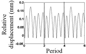
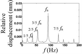
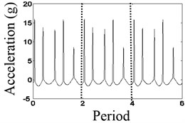
The results are showed in Figs. 4-6 when the vibration frequencies are 2/5fn, 3/7fn and 4/9fn, respectively. In Fig. 4(a), the waveform of the relative displacement has five bounces and five peaks every two revolutions. In Fig. 4(b), the rotational frequency, the larger asynchronous frequency and the natural frequency of the system appear in the spectrum of the relative displacement. In Fig. 4(c), the changing period of stiffness is equivalent to twice the period of the rotating speed, so that 1/2× component appears. In Fig. 4(d), the waveform of the relative acceleration of the mass block has five shocks every two rotations.
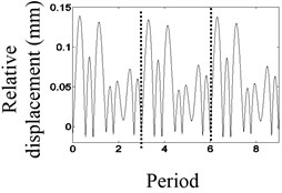
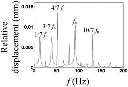
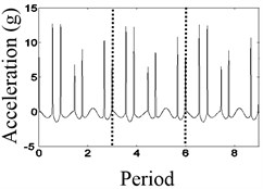
In Fig. 5(a), the waveform of the relative displacement has seven bounces and seven peaks every three revolutions. In Fig. 5(b), the rotational frequency, the larger asynchronous frequency and the natural frequency of the relative displacement appear in the spectrum. In Fig. 5(c), the changing period of stiffness is equivalent to three times the period of the rotating speed, so that 1/3× component appears. In Fig. 5(d), the waveform of the relative acceleration of the mass block has seven shocks every three rotations.
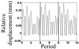
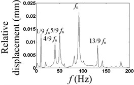
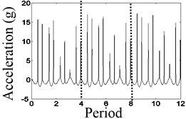
In Fig. 6(a), the waveform of the relative displacement has nine bounces and nine peaks every four revolutions. In Fig. 6(b), the rotational frequency, the stronger asynchronous frequency and the natural frequency of the relative displacement appear in the spectrum. In Fig. 6(c), the changing period of stiffness is equivalent to four times the period of the rotating speed, so that 1/4× component appears. In Fig. 6(d), the waveform of the relative acceleration of the mass block has nine shocks every four rotations.
As can be seen from Figs. 2-6, the natural frequency and asynchronous frequency components are excited. When the rotational frequency equals to 1/J (J= 1, 2…) the natural frequency of system, that is, the changing period of stiffness is equal to the period of the rotating speed, frequency multiplication components appear. When the rotational frequency is equal to J/(2J+1), (J+1)/(2J+1), (2J-1)/(2J) (J= 2, 3…) the natural frequency of system, the changing period of stiffness is equal to n times the period of the rotating speed, then 1/n frequency division components appear, and the natural frequency of system is excited.
Fig. 4Waveform characteristics at 2/5 times the natural frequency
a) Waveform
b) Spectrum
c) Waveform
Fig. 5The waveform characteristics at 3/7 times the natural frequency
a) Waveform
b) Spectrum
c) Waveform
Fig. 6The waveform characteristics at 4/9 times the natural frequency
a) Waveform
b) Spectrum
c) Waveform
Fig. 7Campbell diagram showing under subcritical speeds
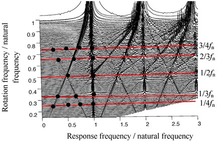
The Campbell diagram of rotor acceleration at the subcritical speeds is shown in Fig. 7. As can be seen from Fig. 7, the looseness fault characteristics are shown as the crossed streaks in the Campbell diagram, which are the asynchronous response frequencies. When the rotational frequencies are 1/4fn, 1/3fn and 1/2fn, frequency multiplication components will appear. When the rotational frequency is 2/3fn, 1/2× and the frequency multiplication components will appear. When the rotational frequency is 3/4fn, 1/3×, 2/3× and the frequency multiplication components will appear. Such similar phenomenon also appears at the transcritical and supercritical speeds.
3. Connector looseness fault experimental verification
3.1. Connector looseness experiment principle
In order to verify the non-synchronous response characteristics of connector looseness fault, the experiment rig with looseness clearance was established, and the connector looseness experiment was carried out. Fig. 8 is the experimental site map of looseness fault. Fig. 9 is the experimental three-dimensional diagram of looseness fault.
Fig. 8The experimental site map of looseness fault: 1 – computer; 2 – NI USB-9234 data acquisition card; 3 – vibration controller; 4 – power amplifier; 5 – the first disk; 6 – the second disk; 7 – the third disk; 8 – acceleration sensor (B&K4508); 9 – acceleration sensor for controller; 10 – vibrating table
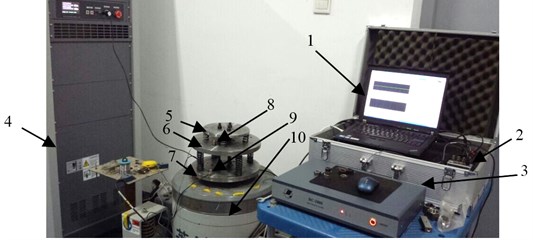
Fig. 9 shows that the second disk is connected to the third disk by spring k1, the third disk is connected to vibrating table by bolts, and the first disk is connected to the third disk by using three polish rods. Then the first disk, the third disk and vibrating table will vibrate together. The first disk and the second disk are connected by spring k2, and the connector looseness fault is simulated by controlling the clearance.
Fig. 9Experimental three-dimensional diagram of looseness fault
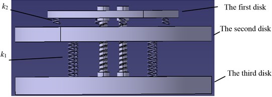
During the experiment, the first disk, the third disk and vibration table vibrate together, and the basement excitation to the second disk is carried out. When the relative displacement between the second disk and the third disk is smaller, the spring k2 does not connect with the second disk, so the spring connection stiffness is only k1. When the relative displacement between the second disk and the third disk is larger, the spring k2 connects with the second disk, so the spring connection stiffness is k1+k2.
The energy of vibrating table was input by power amplifier, and the feedback of vibration signals was realized by controlling the software and the vibration acceleration sensor on the third disk. The vibration of the vibrating table was controlled at the designated frequency and amplitude by vibration controller. The vibration acceleration of the second disk was measured by the vibration acceleration sensor on the second disk. The collected digital signals were input into the computer for preservation by NI USB-9234 capture card.
In order to obtain the vibration performance of the vibration system, the excitation on vibrating table was applied by using the linear sine sweep frequency method from 5 Hz to 100 Hz, and the looseness fault characteristics at different frequencies were obtained.
3.2. Looseness fault experiment verification
3.2.1. Analysis of the second disk response at different contact forms
In the experiment, the acceleration of the second disk are measured by three methods, namely: 1) when the second disk does not contact with the spring k2, the second disk only contacts with the third disk through spring k1, the vibration system is a liner system, and the experiment result is shown in Fig. 10(a); 2) when the second disk always contacts with the spring k2, the second disk contacts with the third disk and the first disk through spring k1 and k2, the vibration system is also a liner system, its spring connection stiffness is k1+k2, and the experiment result is shown in Fig. 10(b); 3) when there is clearance between the second disk and spring k1, at different relative vibration displacement between the second disk and the first disk, the second disk may contacts with spring k1 or not, the vibration system is a nonliner system, and the experiment result is shown in Fig. 10(c).
Fig. 10(a) shows that when the second disk does not contact with the spring k2, the vibration system is a liner system, and its natural frequency is 14.6 Hz. Fig. 10(b) shows that when the second disk always contacts with the spring k2, the vibration system is also a liner system, and its spring connection stiffness is k1+k2, so its natural frequency is 51.22 Hz. When there is looseness clearance, the second disk may contacts with spring k1 or not. According to Eq. (5), the calculated result fn is 22.7 Hz, and the experimental result is 22.2 Hz, shown in Fig. 10(c). Obviously, the analysis results are verified fully.
Fig. 10The response of the second disk under different contact conditions
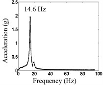
a) No contact between the second disk and spring k2
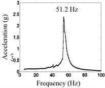
b) Always contact between the second disk and spring k2
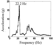
c) Discontinuous contact between the second disk and spring k2
3.2.2. Analysis of looseness characteristics
In order to highlight the period components of vibration frequency, frequency multiplication and frequency division in system, autocorrelation method is used to denoise the acceleration signal of the second disk.
Fig. 11 is cascade plot of the second disk vibration acceleration changing with excitation frequency and response frequency. Fig. 11 shows that the frequency multiplication appears when excitation frequency is 1/2fn, 1/2 frequency division appears when excitation frequency is 2fn, and 1/3 frequency division appears when excitation frequency is 3fn.
Fig. 11Cascade plot of the second disk response
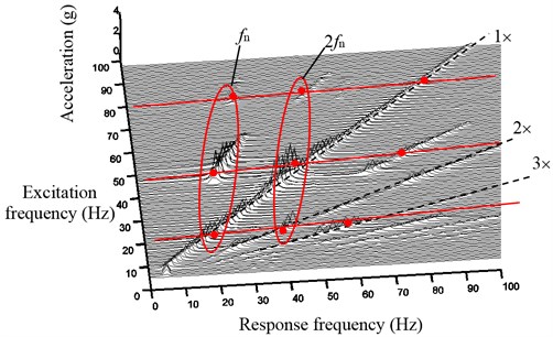
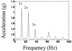
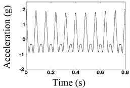
Fig. 12 shows time domain waveform before and after the noise reduction and spectrum before the noise reduction of the second disk when the excitation frequency is 12.5 Hz. As shown in Fig. 12, when the excitation frequency is equivalent to 1/2fn, the larger double frequency components appeared, that is the natural frequency of the system.
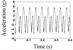
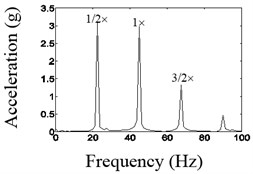
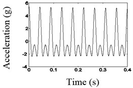
Fig. 13 shows time domain waveform before and after the noise reduction and spectrum before the noise reduction of the second disk when the excitation frequency is 45 Hz. As shown in Fig. 13, when the frequency of the vibration table is equivalent to 2fn, the larger 1/2 dividing frequency components appeared, that is the natural frequency of the system.
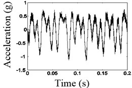
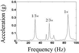
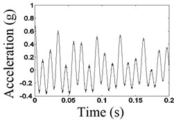
Fig. 14 shows time domain waveform before and after the noise reduction and spectrum before the noise reduction of the second disk when the excitation frequency is 80 Hz. As shown in Fig. 14, when the frequency of the vibrating table is about 3fn, the larger 1/3 dividing frequency components appeared, that is the natural frequency of the system.
As shown in Figs. 12-14, the waveforms after the noise reduction have the characteristics that is a typical shock characteristic, with the waveform of truncated shape, which is longitudinal asymmetrical.
Fig. 12Waveform and frequency spectrum before and after the noise reduction when frequency is 1/2fn
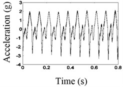
a) The waveform before noise reduction
b) The spectrum before noise reduction
c) The waveform after noise reduction
Fig. 13Waveform and frequency spectrum before and after the noise reduction when frequency is 2fn
a) The waveform before noise reduction
b) The spectrum before noise reduction
c) The waveform after noise reduction
Fig. 14Waveform and frequency spectrum before and after the noise reduction when frequency is 2fn
a) The waveform before noise reduction
b) The spectrum before noise reduction
c) The waveform after noise reduction
By comparison, in different frequencies of the vibrating table, for connector looseness fault, the acceleration waveforms after the noise reduction of autocorrelation have the characteristic that is a typical shock characteristic, with the waveform of truncated shape, which is longitudinal asymmetrical, which could be identified as the characteristics of the looseness fault.
4. Conclusion
In this paper, a single degree of freedom lumped mass model with looseness fault is established. Some results are obtained as follows:
1) For the phenomenon of the asynchronous response characteristics, a foundation vibration model with the looseness fault was established; the asynchronous response characteristics were analyzed.
2) Experiments on connectors with looseness clearance were conducted. It is found that the acceleration response after noise reduction has up-down asymmetrical impact characteristics in the waveform and the pseudo-critical subharmonic resonance and the pseudo-critical ultra-harmonic resonance appear in frequency spectrum. These characteristics are in agreement with the results of the numerical simulation, which can be identified as the characteristics of the looseness fault.
3) By the numerical simulation, the reason leading to the looseness characteristics is that the period of stiffness changes in the period of the rotating speed. When the changing period of stiffness is equivalent to the vibration period, frequency multiplication will appear and the natural frequency of the system will be excited at specific speeds. When the changing period of stiffness is equivalent to n times the vibration period, 1/n frequency division and frequency multiplication will appear and the natural frequency of the system will be excited at specific speeds.
References
-
Fredric F. Ehrich A new class of asynchronous rotor dynamic response in high-speed rotors. Proceedings of the ASME Design Engineering Technical Conferences and Computers and Information in Engineering Conference, 2007, p. 1783-1788.
-
Muszynska A., Goldman P. Chaotic responses of unbalanced rotor bearing stator systems with looseness or rubs. Chaos. Solitons and Fractals, Vol. 5, Issue 9, 1995, p. 1683-1704.
-
Chen Yushu, Li Shihai A method for finding the sub/super harmonic resonance solution of second order nonlinear differential equation and its application. ACTA Mechanica Sinica, Vol. 18, Issue 4, 1986, p. 341-349, (in Chinese).
-
Chu F., Tang Y. Stability and non-linear responses of a rotor-bearing system with pedestal looseness. Journal of Sound and Vibration, Vol. 5, 2001, p. 879-893.
-
Chen Guo Nonlinear dynamic of unbalance-looseness coupling faults of rotor-ball bearing-stator coupling system. Journal of Mechanical Engineering, Vol. 44, Issue 3, 2008, p. 82-88, (in Chinese).
-
Hui Ma, Xueyan Zhao, Yunnan Teng, et al. Analysis of dynamic characteristics for a rotor system with pedestal looseness. Shock and Vibration, Vol. 18, 2011, p. 13-27.
-
Goldman P., Muszynska A. Smoothing technique for rub or looseness-related rotor dynamic problem. Proceedings of the 15th ASME Biennial Vibration and Noise Conference, 1995, p. 565-572.
-
Lu W., Chu F. Experimental investigation of pedestal looseness in a rotor-bearing system. Key Engineering Materials, Vols. 413-414, 2009, p. 599-605.
-
Ji Z., Zu J. W. Method of multiple scales for vibration analysis of rotor-shaft systems with non-linear bearing pedestal model. Journal of Sound and Vibration, Vol. 218, Issue 2, 1998, p. 293-305.
-
Behzad M., Asayeshthe M. Numerical and experimental investigation on vibration of rotors with loose disks. Proceedings of the Institution of Mechanical Engineers, Part C: Journal of Mechanical Engineering Science, Vol. 223, 2009, p. 1-10.
-
Chen Guo A coupling dynamic model for whole aero-engine vibration and its verification. Journal of Aerospace Power, Vol. 27, Issue 2, 2012, p. 242-254, (in Chinese).
-
Aeroengine Design Manual Compiling Committee. Aero-engine Design Manual 19th Part: Rotor Dynamics and Whole-Engine Vibration. Aviation Industry Press, Beijing, 2000, p. 208-226, (in Chinese).
-
Zhai W. M. Two simple fast integration methods for large-scale dynamic problems in engineering. International Journal for Numerical Methods in Engineering, Vol. 39, Issue 24, 1996, p. 4199-4214.
About this article
This work is supported by Funding of Jiangsu Innovation Program for Graduate Education KYLX_0295, the Fundamental Research Funds for the Central Universities and the NUAA Fundamental Research Funds, No. NS2013070.
