Abstract
A mathematical model for the shrouded blades in aircraft engines is developed under the consideration of the friction and impact to study the dynamic mechanism and the effect of parameters for the system on responses. Aircraft engine blades experience excessive vibrations due to the gas excitation forces during operation. The blade vibrations lead to high dynamic stress that may cause high cyclic fatigue failure (HCF). A model which is made up of springs, damping and a beam carrying a concentrated mass is established to simulate the cyclic symmetry structure of the shrouded blades. The independent mass effect of the shrouds is taken into account in this model. It is closer to the reality that the shroud is regarded as a mass instead of only a part of the beam and the centrifugal force is accounted for in the equation of motion. The Euler-Bernoulli beam theory is adopted to obtain the equation of motion with consideration of the gas excitation forces, the rotational speed effect and the combined effect of the impact and friction between shrouds. The parametric analysis is carried out to study the influence of the contact angle, the friction coefficient, the stiffness and the gap between the shrouds on the responses. Numerical results show that there exists an optimum value of the contact angle for a better damping effect. The nonlinear characteristic, which is derived from the impact and contact, is briefly showed in this paper.
1. Introduction
In the aerospace industry, failure of blade accounts for a large part of the failures in engines. Failure of blade occurs due to high cyclic fatigue (HCF) which is caused by high dynamic stress. High dynamic stress is resultant of the severe blade vibrations when the blades rotate at a high rotational speed during operation. To reduce the vibration of the blade, a common approach is adding a shroud to each blade. A shroud impacts with the adjacent shrouds to generate a damping from the friction and impact between the shrouds when the aero-engine is operating. Such approach has been widely used in engineering practice and has been proven to be effective in reducing vibrations.
To facilitate the design of the shrouds to achieve an optimal damping effect, it is essential to study the dynamic mechanisms of the friction and impact during the shrouds. In the past several decades, both the development of analytical model and the solution of the equation have been conducted to analyze the dynamic behavior of the shrouded blade. J. Szwedowicz et al. [1] carried out a numerical prediction of the forced vibrations of a disk assembly with the consideration of the frictional effects between the shrouds concerning engineering needs for the blade design process; the researchers took the friction nonlinearities into account. Full cycle of the blades [2] and the friction contact models [3, 4] were developed to conduct the dynamic analysis. Yang B. D. and C. H. Menq [5] studied on a three-dimensional model of a damper for the blade. Q. Ding et al. [6] investigated a system with a dry friction damper; they divided a vibration cycle into several periods to analyze the steady state response of the blade. E. Cigeroglu et al. [7] proposed a lumped parametric model for a tip-shrouded bladed disk to study the nonlinear characteristics of the system. Many researchers all focused on the mistuning bladed discs [8-10] and obtained much of important progress. R. Wadia and P. N. Szucs [11] numerically reported on the different performances between the shrouded and the unshrouded fan blades. Bo-Wun Huang [12] investigated the phenomenon of the mode localization as a result of a crack. Dong-Ho Rhee and Hyung Hee Cho [13] studied the influence of the blade position on the heat transfer in a blade and a shroud. Ibrahim Ata Sever [14] carried out some experiments to validate the reliability of the numerical models. J. J. Kielb and R. S. Abhari [15] studied the aerodynamic characteristics and the structural damping in shrouded blades. Corso Padova and Jeffery Barton [16] investigated the aeromechanic phenomena for the gas turbine engines by an experimental method. Hong Seok Lim and Hong Hee Yoo [17] presented a modeling approach for analyzing a rotational beam carrying a lumped mass collided by a particle mass. Krzysztof Czołczynski and Tomasz Kapitaniak [18] researched on the influence of the parameters on the periodic motion for two impacting oscillators. E. P. Petrov [19] developed an effective approach to analyze multi-harmonic vibrations of the bladed disks. D. Cao etc. [20] proposed an approximate method to study the problem of the friction contact. They treated the friction and impact as a piecewise problem and analyzed the nonlinear vibrational characteristics due to tip-rub.
Although much of research has been done on the dynamic behavior of the shrouded blade systems, most of the studies focused only on the friction contact problems between the shrouds with relation to the friction contact performances. The combined effect of the impact and friction between shrouds has not been studied fully in the published articles and the rotational speed has seldom been considered to study the influence of the centrifugal forces on vibrational characteristics. This paper will address the lack of the research on the friction and the impact vibrations between the shrouds with consideration of the effect of the rotating speed. Moreover, it is not close to the reality that some researchers regarded the shrouded blades as only a cantilever instead of consideration of the independent mass effect of the shrouds. In order to investigate the friction and impact under the effect of the rotating speed, a model composed of springs and a cantilever beam carrying a centralized mass is developed to simulate the cyclic symmetry structure of the shrouded blade in the aero-engines. Parametric analysis will be carried out in this paper; and the nonlinear characteristic of the system will be showed by using the phase diagrams, the bifurcation diagrams and Poincare sections.
2. Modeling and equations of motion
To study the dynamic mechanism of a shrouded blade, an analytical model (Cantilever-Mass-Springs Model) is utilized to simulate the shrouded blade with a parallelogram shroud. For simplicity, the blade is approximated as a cantilever beam, and the shroud is equivalent to an added mass m. Some researchers modeled the whole shrouded blade into only a cantilever and did not consider the independent mass of the shroud. The Cantilever-Mass-Springs Model is closer to the reality by considering the distribution of the internal mass for the system. The shrouds impact and rub with each other if the system is placed into a centrifugal force field where the rotating speed is Ω. The coordinate system is defined in accordance with the radial (X), transverse (Y) (i.e. tangential direction) and axial (Z) directions, as shown in Fig. 1. The right upper view of Fig. 1 is the top view of the shrouded blades system and the lower right one is the schematic view of the upper one. Accordingly, the shrouded blades have three vibrations in the radial, transverse and the axial directions. The transverse vibration is focused on in this paper.
Fig. 1Schematic diagram of the mathematical model for the shrouded blade
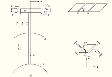
Taking a differential segment of the beam with the length of dx and analyzing the equilibrium of the forces in the transverse direction where there are shear force Q and Q+dQ acting on the cross section, faxial∂v(x,t)∂x and faxial∂v(x,t)∂x+d(faxial∂v(x,t)∂x) that is the component force of the axial force faxialin the transverse direction, the vicious force c∂v(x,t)∂tdx, the gas excitation fgas, contact force at the free end of the beam if the beam collides with the spring, and then summing the forces of the transverse direction, the following equation of motion for the rotating beam can be obtained:
=faxial∂2v(x,t)∂x2-ρAxΩ2∂v(x,t)∂t+fgas+(fnsinα+fτcosα)δ(x-l),
where fn represents the normal contact force between the interfaces of the shrouds, fτ means the tangent contact force between the interfaces; δ(x-l) is the Dirac delta function. Here it equals to zero if x is not equal to l (l means the length of the beam) and it is equal to zero if x equals to l. The axial force of the beam at the position x i.e. centrifugal force, is:
The gas excitation force:
where f0sinωt is the excitation force caused by the centrifugal force, ω=2πfd here fd is the dynamic frequency of the blade; f1sinω1t is the gas excitation force from the nozzle, ω1 is the circular frequency. The blade is excited once when it rotates through one nozzle, thereby the blade is exerted by a periodic excitation if the blade rotates with a constant speed. An assumption is proposed that the number of the nozzles for a whole circle is Z1, the number of the excitation is Z1 when the blade rotates one circle. If the rotational speed is ns (round/second), then the frequency of the excitation is Z1ns. It is assumed that there are three nozzles in the whole circle in this paper, i.e. Z1=3, and then the frequency of the gas excitation is 3ns, i.e. ω1=3ω. If there is no gas excitation force, f1=0. The vibration characteristic with the nozzle is studied in this paper. The normal force in the contact face:
The normal force is piecewise linear and is actually nonlinear due to the discontinuity. The friction force in the contact face:
where f(vrela) is the friction, μk is the friction coefficient for slide, μs is friction coefficient for static, N is the normal force in interface between the two shrouds, vrela is the relative velocity for slide between the two shrouds; the value equals to zero when the interface between shrouds is at a state of stick. f(vrela) is in the range of -μsN and μsN. The nondimensional equation of the motion can be displayed as:
-ξV'(ξ,τ)+1ρAlΩ2fgas+1ρAlΩ2fnsinα+1ρAlΩ2fτcosα,
with the boundary condition:
where:
Assuming the solution for Eq. (7) as:
where is the coefficient to be determined and is the eigenfunction of the cantilever with the tip mass, which is given as:
where are determined by the following frequency equation:
Substituting Eq. (11) of the first order into Eq. (6) yields the nondimensional temporal equation of motion:
where:
where is the interface force after discretizing, is the normal force after discretizing, is the transverse force after disretizing.
3. Numerical results and analysis
Based on the aforementioned equations, the parameters of the mechanical model, such as the contact angle of the shrouds, the contact stiffness, the friction coefficient during the interfaces and the gap between the shrouds, are analyzed as follows. Fig. 2 shows the time history of the displacement at the tip of the cantilever with the following parameters: the contact angle 60°, the amplitudes of the gas excitation force 300 N, 500 N, the gap between shrouds 0.001 m, the stiffness between shrouds 10000 N/m, the friction coefficient 0.3. It can be seen from Fig. 2 that some ripping harmonic wave appears, this is because the gas excitation force is not harmonic but multi-harmonic, as seen in Eq. (3), the corresponding response is the similar characteristics under the linear system. How the parameters influence on the vibration are analyzed respectively as follows.
Fig. 2Time history of the displacement at the position of the tip beam
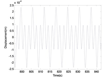
Fig. 3The influence of the contact angle on the response
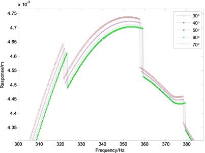
a) Frequency-Response curves
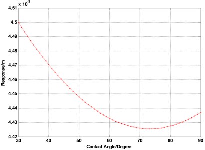
b) Response-Angle curve
Applying software Matlab as the calculation tool, the equation of motion is solved based on the Runge-Kutta method (Variable-step, ode45). The value of Root-Mean-Square (RMS) is chosen to define the response of the vibration at the free end of the blade in the frequency domain. In the case of a set of values , the RMS:
The computational time for Fig. 3(a) is about six and a half hours. The tip amplitude of responses for the shrouded blade system with five different values of the contact angle (seen in Fig. 1) 30°, 40°, 50°, 60° and 70°, respectively, are illustrated in Fig. 3(a) with the RMS of the vibration at the free end of the blade as ordinate against the frequency as abscissa. It can be seen from Fig. 3(a) the contact angle have certain effect on the peak frequency for the response but the effect is not obvious (0.5 %). There is a special phenomenon that three jumps appear when the frequency is in the vicinity of 322 Hz, 359 Hz and 378 Hz respectively. This type of jumping behavior is a sudden change of the response when the rotational speed runs up to a certain value. The similar characteristics will appear in the following parametric study. The jump phenomenon can be explained by the nonlinearity from the impact and the friction existing in the system. The related nonlinear characteristics can be shown in bifurcation diagram, as seen in Fig. 7. It can be seen from Fig. 3(b) that the amplitude of the response changes with the increasing contact angle. The amplitude decreases when the contact angle increases up to 73° from 30° and the amplitude increases when the contact angle exceeds 73°. The angle value 73° is the inflection point where the response is the lowest and this value can be applied to the design of the contact angle to get a better effect of the vibration reduction.
Fig. 4The influence of the stiffness on the vibration
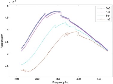
Fig. 5The influence of the gap between shrouds on the vibration
The stiffness in this paper refers to the contact stiffness between the shrouds. The tip amplitude of responses of the shrouded blade system, with the four different values of the stiffness, i.e., 5×10³, 1×10⁴, 5×10⁴ and 1×10⁵, at a range of frequency from 200 Hz to 500 Hz, are presented in Fig. 4 where the ordinate is the RMS for the vibration at the free end of the blade and the abscissa is the frequency. It can be seen from Fig. 4 the response is very high as the stiffness equals to 5×10³. These values of the stiffness are not available in practical engineering and should be avoided in the design of the shrouded blades. As the stiffness increases, the response deceases. The stiffness has an obvious effect on the resonant frequency, which increases with the increasing stiffness. When the frequency increases up to 470 Hz, the responses of all stiffness values is almost identical the stiffness has a little effect on the frequency when the stiffness is from 5×10³ to 1×10⁴. Moreover, the curves are not smooth at some frequencies, this is because the nonlinearity appears in the span of the frequency. It will be studied in the following section. The effect of the stiffness on the response can be calculated quantitatively by using this method. Incidentally, the nonlinear phenomenon derived from the impact and the friction appears.
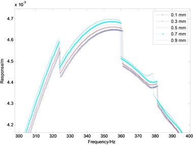
The corresponding tip responses of the shrouded blade system, with the five different values of the gap between the shrouds, 0, 0.2, 0.4, 0.6, 0.8 and 1.0 mm, are shown in Fig. 5. It can be observed from Fig. 5 that the response varies with the gap between the shrouds. As the gap of shrouds increases from 0.1 to 0.9 mm, the maximum response increases; the gap between the shrouds actually is a constraint of the vibration for the blade; while the dimension of the gap is the intensity of the constraint. Therefore, increasing the gap leads to the increasing response under the certain scope of the other parameters. The gap has little effect on the resonance frequency of the peak response. It is essential to design the proper gap for reducing vibration in practical engineering. It is noteworthy that there existed some sudden change of the responses, for example, near the value of the frequency 325 Hz and 360 Hz. The sudden jump of the responses derive from the piecewise nonlinearity in the system.
The responses of the shrouded blade system with the four different values of the friction coefficient, 0.1, 0.3, 0.5 and 0.7 with an exciting frequency range from 300 Hz to 400 Hz, are plotted in Fig. 6. It can be seen from Fig. 6 that the response varies with the increasing friction coefficient, but the effect is weak. It can be seen from Fig. 6 the peak response decreases as the friction coefficient increases; the percentage of the decrease is only 0.85 %; and the friction coefficient has a little effect on the resonance frequency, which increases 0.83 % when the friction coefficient increases from 0.2 to 0.8. The response for the different values of friction coefficient is nearly equal when the frequency increases up to 400 Hz. The jumping phenomenon incidentally appears with the whole process.
Fig. 6The influence of the friction coefficient on the vibration
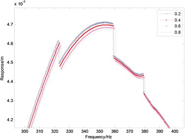
Fig. 7Bifurcation diagram for Ω= 1000-8000 r/min
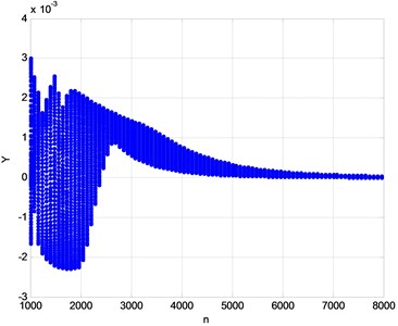
Considering the combined effect of the impact and friction under the rotating speed, the system is substantially a piecewise system which has nonlinear characteristic. In order to study the nonlinearity of the system, bifurcation diagram, phase diagrams and Poincare diagrams are employed to analyze the nonlinear behavior of the shrouded blades. Fig. 7 is the bifurcation where the displacement at the free end of the blade is used as the ordinate against the rotating speed (r/min) as the abscissa. The wide chaotic region of the span 1000-2000 r/min becomes the narrow and steady region of the span for the rotating speed greater than 6000 r/min; and the response is not regular in the span of chaotic state. For example, when the rotating speed is 1500 r/min, the response is on a steep small peak of response and the response suddenly decreases (just like jump) due to the steep cliff of response when the rotating speed increases a little bit. This chaotic characteristic accords with the jumping phenomenon in the response-frequency figures.
Poincare section is an analytical tool to judge the form of motion in a nonlinear system. Poincare sections are shown in Fig. 8. It can be seen from the bifurcation that the system exhibits a disorder and irregular response at lower speeds. By analyzing the whole fluky region of the response in bifurcation, a typical Poincare section at 1460 r/min is shown in Fig. 8(a) where the shape is chaotic and wriggly. When the rotating speed increases up to 4000 r/min, the Poincare section is transformed into a quasi-periodic orbit whose Poincare section is shown in Fig. 8(b). On a further increase in the rotating speed, the quasi-periodic orbit loses the stability and is transformed into a periodic orbit, as seen in Fig. 8(c). In brief, it can be drawn from the Poincare sections that the system is a nonlinear system, which exhibits a rich nonlinear characteristics, including the periodic, quasi-periodic, chaos, etc.
Phase diagram is the geometrical expression of the trajectory for the state in the phase plane. From the phase diagram, the stability and the asymptotic stability can be judged. One calculated and obtained the displacement and velocity at the free end of the blade against the various time and applied the data to the abscissa and ordinate, respectively. It can be seen from Fig. 9(a) and 9(b) that the trajectory changes from a) to b) with the various rotating speed, i.e. from the quasi-periodic regime to periodic regime. The stability changes when the rotating speed increases through the critical values. Hence, it is understandable for the aforementioned jump phenomenon.
Fig. 8Poincare sections
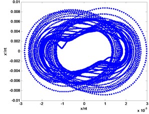
a)1460 r/min
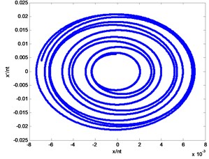
b)4000 r/min
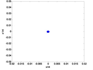
c)7300 r/min
Fig. 9Phase diagram
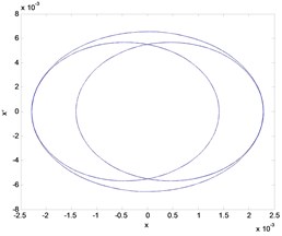
a)2006 r/min
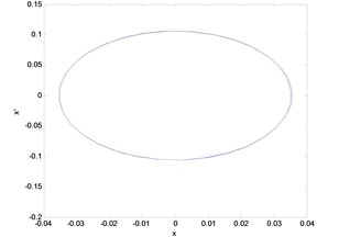
b)4013 r/min
4. Conclusions
In this paper, considering the combined effect of the impact and friction between the shrouded blades under the influence of the rotating speed force, a mathematical model is established to study the effects of the parameters on the dynamic characteristics of the shrouded blades; and the nonlinear analysis is carried out briefly. The main conclusions are as follows:
1) The contact angle, the gap and the friction coefficient have little effect on the resonance frequency of the peak response; while the stiffness has a larger effect on the resonance frequency and the response. How the effect is can be calculated quantitatively by the method of this paper;
2) There exists a critical contact angle (73°) where the response is the lowest and the value can be applied to the design of the contact angle in order to get a better effect of reducing vibration;
3) Simulation results show that the parameters have effects each other. Consequently, it is necessary to consider the parameters overall and adopt a prudent design of parameter for the shrouded blades;
4) The system shows the jumping phenomenon and the disorder curves which are the nonlinear characteristics because of the friction and the impact. The method in this paper offers an analytical model for the nonlinearity. The quantitative analytical approach of the parameters in this study can be extended to analyze other rotating machinery.
References
-
Szwedowicz J., Visser R., Sextro W., Masserey P. A. On nonlinear forced vibration of shrouded turbine blades. Journal of Turbomachinery, Vol. 130, 2008, p. 011002.
-
Tsai Gwo-Chung Rotating vibration behavior of the turbine blades with different groups of blades. Journal of Sound and Vibration, Vol. 271, 2004, p. 547-575.
-
Koh K.-H., Griffin J. H., Filippi S., Akay A. Characterization of turbine blade friction dampers. Transactions of the ASME, Vol. 127, 2005, p. 856-862.
-
Allara M. A model for the characterization of friction contacts in turbine blades. Journal of Sound and Vibration, Vol. 320, 2009, p. 527-544.
-
Yang B. D., Menq C. H. Characterization of 3D contact kinematics and prediction of resonant response of structure having 3D friction constraint. Journal of Sound and Vibration, Vol. 217, Issue 5, 1998, p. 909-925.
-
Ding Q., Chen Y. Analyzing resonant response of a system with dry friction damper using an aero-engine. Journal of Vibration and Control, Vol. 14, Issue 8, 2008, p. 1111-1123.
-
Cigeroglu E., Ozguven H. Nevzat nonlinear vibration analysis of bladed disks with dry friction dampers. Journal of Sound and Vibration, Vol. 295, 2006, p. 1028-1043.
-
Kenyon J. A., Griffin J. H. Forced response of turbine engine bladed disks and sensitivity to harmonic mistuning. Journal of Engineering for Gas Turbines and Power, Vol. 125, 2003, p. 113-120.
-
Chan Yum Ji Variability of Blade Vibration in Mistuned Bladed Discs. A Thesis submitted to the University of London for the degree of Doctor of Philosophy. Department of Mechanical Engineering Imperial College London, 2009.
-
Feiner D. M., Griffin J. H. A fundamental model of mistuning for a single family of modes. Journal of Turbomachinery Copyright, Vol. 124, 2002, p. 597-605.
-
Wadia R., Szucs P. N. Inner workings of shrouded and unshrouded transonic fan blades. Journal of Turbomachinery, Vol. 130, 2008, p. 031010.
-
Huang Bo-Wun Effect of number of blades and distribution of cracks on vibration localization in a cracked pre-twisted blade system. International Journal of Mechanical Sciences, Vol. 48, 2006, p. 1-10.
-
Rhee Dong-Ho, Hyung Hee Cho Effect of vane/blade relative position on heat transfer characteristics in a stationary turbine blade: Part 1. Tip and shroud. International Journal of Thermal Sciences, Vol. 47, 2008, p. 1528-1543.
-
Ibrahim AtaSever Experimental Validation of Turbomachinery Blade Vibration Vibration Predictions. A Thesis submitted to the University of London for the degree of Doctor of Philosophy. Department of Mechanical Engineering Imperial College London, 2004.
-
Kielb J. J., Abhari R. S. Experimental study of aerodynamic and structural damping in a full-scale rotating turbine. Transactions of the ASME, Vol. 125, 2003, p. 102-112.
-
Padova Corso, Barton Jeffery Experimental results from controlled blade tip/shroud rubs at engine speed. Journal of Turbomachinery Copyright, Vol. 129, 2007, p. 713-724.
-
Lim Hong Seok, Yoo Hong Hee Dynamic impact analysis of a rotating beam having a tip mass. Key Engineering Materials, Vols. 321-323, 2006, p. 1649-1653.
-
Czołczynski Krzysztof, Kapitaniak Tomasz Influence of the mass and stiffness ratio on a periodic motion of two impacting oscillators. Chaos, Solitons and Fractals, Vol. 17, 2003, p. 1-10.
-
Petrov E. P. A method for use of cyclic symmetry properties in analysis of nonlinear multiharmonic vibrations of bladed disks. Journal of Turbomachinery, Vols. 126-175, 2004.
-
Cao D., Gong X., et al. Nonlinear vibration characteristics of a flexible blade with friction damping due to tip-rub. Shock and Vibration, Vol. 18, 2011, p. 105-114.
-
Chen J. J., Menq C. H. Periodic response of blades having three-dimensional nonlinear shroud constraints. Journal of Engineering for Gas Turbines and Power, Vol. 123, 2001, p. 901-909.
-
Lim Hong Seok, Yoo Hong Hee Dynamic impact analysis of a rotating beam having a tip mass. Key Engineering Materials, Vols. 321-323, 2006, p. 1649-1653.
-
Tatsuhito Hiroyuki, et al. Analysis of steady collision vibration in cantilever beam having attached mass. Journal of System Design and Dynamics, Vol. 3, Issue 6, 2009.
-
Watanabe T., Shibata H. On Nonlinear Vibration of a Beam Response of a Beam with a Gap at One End. Report of the Institute of Industrial Science the University of Tokyo, Vol. 36, Issue 1, 1991, p. 1-25.
About this article
The authors acknowledge the support of the National Natural Science Foundation of China (Grant No. 51305267).
