Abstract
A turbofan nonlinear dynamic model is described in the paper. It has been developed for the computation of loads in the engine frame after fan blade-out (FBO) event. The model includes reduced dynamic finite element models of rotors and casings and also nonlinear elements for simulation of “rotor-casing” contact interactions. Thorough attention has been paid to mounts modeling with possible mechanisms taken into account. The engine dynamic behavior during its rotors deceleration to the autorotation mode after the FBO event has been simulated for the following two forward mount arrangement variants: fastening to the inner part of the intermediate casing; fastening to the outer part of the intermediate casing. The effect of load reduction device (LRD) – special elements which are introduced to fan supports, destroyed under certain force and don’t transfer improper loads to the engine casing system after the FBO event, has been studied. The analysis of maximum loads on engine mounts has been performed for the two listed design variants for both cases: with and without an LRD in fan supports.
1. Introduction
Fan blade out event is the load case which determines limit loads on engine frame elements. As a result of this event the released blade may break through the fan casing and also the engine frame elements might be destroyed under rotating unbalance force. Regulatory documents [1, 2] demand that FBO event must not lead to the listed catastrophic consequences. Thereby the designer should estimate mount loads caused by unbalance after FBO event.
The centrifugal force after FBO event may reach the values about 1.0∙106 N at maximum turbofan rotors velocities. This value is significantly more than loads caused by regular unbalances. The engine rotors are deformed under applied loads and blades may scrape the engine casings. The unbalance force is transferred through the rotor and its bearings to rotor supports, engine casings system and finally to mounts. The maximum loads in the turbofan frame elements after FBO event may occur either at the moment of FBO, when the unbalance force is applied, or at passing resonance during rotor slowing down. Complexity of the dynamic process and necessity of taking into consideration rotors and stators stiffness and inertial properties, gyroscopic effect, load application instant character and rotor deceleration law lead to demand of the special engine dynamic model for frame loads computation after FBO event.
The number of researches has been dedicated designing dynamic model of the rotor or the whole engine in order to calculate engine frame loads after FBO event [3-10]. The main approaches used in these papers are the following: simulation of full 3D finite element (FE) engine model during relatively short time interval [3-6] and use of the reduced model for the whole time interval, which is of great interest [7, 8]. The intermediate approach was developed in [9, 10], it includes full FE simulation of dynamics at the process beginning and simplified simulation during the rest part of the process. However, the contact interactions are not taken into account at the 2nd, the longest, process stage in these researches. This paper is the next step in the research described in [8].
The way in which engine mounts are arranged is one of the most important factors influencing the engine frame elements loads. The main variants of the engine front mount arrangement are following:
• Front mount is fastened to inner shell of the intermediate casing, the thrust is transferred through the same place; the front mount transmits the axial, vertical and side forces, the aft mount – the vertical and side forces and the torque.
• Front mount is fastened to outer shell of the intermediate casing, the thrust is transferred from the casing inner shell through special rods to the aft mount; the front mount transmits the vertical and side forces, the aft mount – the axial, vertical and side forces and the torque.
The examples of the listed mount arrangement variants are shown in Fig. 1.
Fig. 1The examples of turbofans with different mount arrangement types
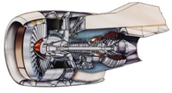
a) First variant – PW4000 engine
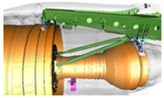
b) Second variant – GEnx engine
This current paper describes the MSC Nastran dynamic engine model for frame loads computation after FBO event. The two variants of engine mount arrangements are considered and corresponding dynamic loads after FBO event are compared.
2. Mathematical model
The 3D FE models of typical turbofan rotors and casings have been developed. The example of rotor FE model is shown in Fig. 2. The example of casing FE model is shown in Fig. 3. Static condensation technique [11] is used to reduce the number of computational model’s degrees of freedom. The application of this method is common for solving problems of rotating systems dynamics, [12-14]. However, it is possible to use more precise reduction techniques [15].
Fig. 2Example of rotor FE model longitudinal section
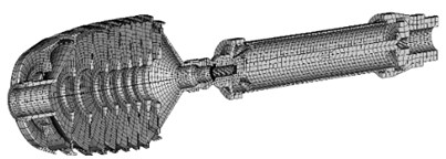
Fig. 3Example of casing FE model
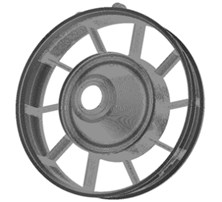
Rotors models are reduced to master nodes which are located at the engine axis and connected to 3D FE model by multi-point constraints (MPC). Stiffness and inertial properties of the casings models are condensed to the nodes at centers of the mount joints and to a large number of master nodes at every flange. During rotors reduction procedure the matching of full and reduced FE models eigenfrequencies is checked, during casings reduction procedure the matching of full and reduced FE models flexibilities is checked for the whole engine casing assembly with fixed (casing-to-mount) junction nodes.
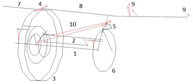
The dynamic engine model in pre-, postprocessor Patran with first variant of mount arrangement is shown in Fig. 4, with second variant of mount arrangement – in Fig. 5. In both cases the model includes: low pressure (LP) and high pressure (HP) rotors, fan casing, HP compressor casing, combustor chamber casing, LP and HP turbine casings, intermediate casing, fan supports, HP and LP turbine supports, booster and fan casings, front and aft mounts, pylon. Thorough attention has been paid to mounts modeling with hinge mechanisms taken into account.
Fig. 4Engine model in Patran with first variant of mount arrangement. 1 – LP rotor, 2 – HP rotor, 3 – intermediate casing, 4 – forward mount, 5 – aft mount, 6 – LP turbine support, 7 – fan casing, 8 – pylon, 9 – pylon-to-wing attachment points
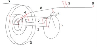
Fig. 5Engine model in Patran with second variant of mount arrangement. 1 – LP rotor, 2 – HP rotor, 3 – intermediate casing, 4 – forward mount, 5 – aft mount, 6 – LP turbine support, 7 – fan casing, 8 – pylon, 9 – pylon-to-wing attachment points, 10 – thrust rods
The model considers rotor-stator as well as rotor-rotor contacts. The contact is modeled by axisymmetric (point-point) contact element NLRGAP, which applies radial restoring force to both inner and outer points, if their relative displacement exceeds radial clearance. Detailed description of contact interactions modeling is given in paper [8]. Bearings were modeled as linear elastic elements. Though, more precise nonlinear bearing models can be used [16-18].
The problem is formulated as nonlinear differential equations system Eq. (1), which is solved iteratively in time domain, resulting in nonstationary process:
where {x} – system DOF vector, [M] – mass matrix, [K] – stiffness matrix, [D] – damping matrix, [G] – gyroscopic matrix, {f} – force vector, which includes rotating centrifugal force and nonlinear contact forces.
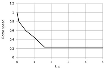
The assumed LP rotor deceleration curve is shown in Fig. 6. The angular velocity values are normalized to maximum angular velocity. It is needed to pay special attention to the fact that rotor does not stop its rotation, it slows down to autorotation frequency maintained by air flow. The greatest interest in this work are the maximum values of engine mount loads. This maximum is usually achieved at resonance pass during rotor deceleration. However, the behavior of the rotor on the autorotation mode should also be properly studied [19, 20]. Structural damping used in the model is equal to 12.5 % of critical damping at maximum operating rotating speed.
Implementation of the static condensation method for engine model development makes it impossible to take into account large displacements and non-linear material properties. This factors can be considered both in terms of simplified approaches [21, 22], and with full three-dimensional modeling [3-5, 9, 10]. Let us note that, nonlinear material properties account will not have a significant impact on engine mounts load values [10].
Fig. 6Time history of dimensionless LP rotor speed after FBO
3. Simulation results
The computation results of engine mounts dynamic loads for the first variant of mounts arrangement are shown in the Fig. 7, for the second variant – in the Fig. 8. The presented values of forces were computed as geometrical sums of three orthogonal projections of corresponding forces vectors. All forces are normalized to unbalanced centrifugal force after FBO event at maximum rotor speed. The figures show that if the first mount arrangement variant is chosen, the maximum loads at front and aft mounts relate as 2:1, if the second mount arrangement variant is chosen – 1:3.5. The maximum loads are 20 % less in the second variant (0.5 vs 0.6). In all cases the maximum loads are achieved in 0.3-0.5 s after FBO event, i.e. when fan rotor speed is about 30-40 % less than its maximum value.
Fig. 7Time histories of dimensionless engine mounts loads after FBO with the first mount arrangement variant
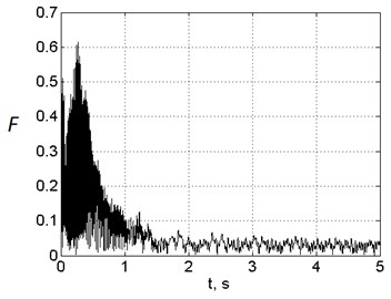
a) Front mount
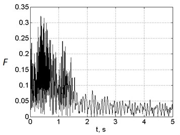
b) Aft mount
Fig. 8Time histories of dimensionless engine mounts loads after FBO with the second mount arrangement variant
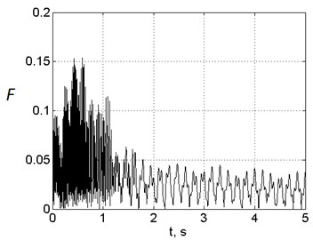
a) Front mount
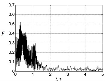
b) Aft mount
4. Load reduction device effect
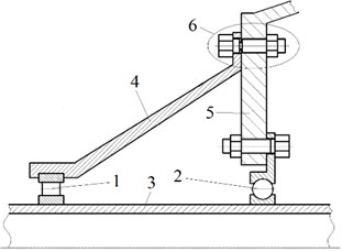
A special device is implemented in civil aircraft engines design to reduce the maximum engine mount loads after FBO event (load reduction device – LRD). It is a set of bolts with weakened cross-sections, which are destroyed under certain loads. After the LRD has been actuated front fan support disconnects and stops responding to the load. Consequently, properties of the dynamic engine structure are changed. The example of LRD design is shown in the Fig. 9. The study of LRD influence on the engine frame loads was performed in [7, 8, 23].
Fig. 9Fan supports and load reduction device: 1, 2 – fan bearings, 3 – fan shaft, 4, 5 – fan supports, 6 – load reduction device
The computations of engine dynamic behavior after FBO event with LRD implemented in fan supports design are performed in the current research for both variants of mount arrangements. Computation results are presented in the Tables 1, 2. As it can be seen from these tables, if LRD is implemented in fan supports, maximum loads reach their minimum in the case of first mount arrangement variant. Let us note that LRD introduction almost does not change loads in the second variant of mount arrangement.
Table 1Maximum normalized loads in engine mounts for the first mount arrangement variant
Place of load measurement | Without LRD | With LRD |
Forward mount | 0.6114 | 0.217 |
Aft mount | 0.3212 | 0.4503 |
Table 2Maximum normalized loads in engine mounts for the second mount arrangement variant
Place of load measurement | Without LRD | With LRD |
Forward mount | 0.1538 | 0.1542 |
Aft mount | 0.5201 | 0.5196 |
5. Conclusions
This paper is dedicated to the turbofan nonlinear dynamic model. It includes reduced models of rotors and casings and also possible contact interactions between them. The results of computation of engine dynamic behavior under the unbalanced force caused by FBO event show that in the considered example maximum mount loads are achieved when passing the resonance during rotors run-out. Mount loads are not maximum at the FBO moment. The pick values of mount loads are minimal if the first mount arrangement variant is used together with LRD in fan supports. If there is no LRD, the maximum loads are minimal when the second mount arrangement variant is used. These conclusions cannot be expanded to all civil turbofans. Engine dynamic behavior computations should be performed for every specific engine design taking into account stored experimental data about rotors deceleration curves after FBO event and system damping values.
References
-
Federal Aviation Regulations. Part 33 – Airworthiness Standards: Aircraft Engines. Federal Aviation Administration, 1992.
-
Certification Specifications and Acceptable Means of Compliance for Engines, CS-E. Amendment 4, European Aviation Safety Agency, 2015.
-
Shmotin Y., Gabov D., Ryabov A., Kukanov S., Rechkin V. Numerical analysis of aircraft engine fan blade-out. 42nd AIAA /ASME/SAE/ASEE Joint Propulsion Conference and Exhibit, 2006.
-
Carney K. S., Lawrence C., Carney D. V. Aircraft engine blade-out dynamics. 7th International LS-DYNA Users Conference, 2002, p. 14-17.
-
Husband J. B. Developing an Efficient FEM Structural Simulation of a Fan Blade Off Test in a Turbofan Jet Engine. Ph.D. Thesis, University of Saskatchewan, Saskatoon, Saskatcheven, Canada, 2007.
-
Sinha S. K., Dorbala S. Dynamic loads in the fan containment structure of a turbofan engine. Journal of Aerospace Engineering, Vol. 22, Issue 3, 2009, p. 260-269.
-
Ivanov I. I. On the choice of parameters of device to reduce load on components of turbojet engine pressure vessels after fan blade breakage. Proceedings of Higher Educational Institutions. Machine Building, Vol. 10, Issue 631, 2015, p. 3-11.
-
Ivanov I. I., Blinnik B. S. Dynamic loads acting on engine frame elements after fan blade out event study. 29th Congress of the International Council of the Aeronautical Science, St. Petersburg, Russia, 2014
-
Heidari M., Carlson D., Sinha S., Sadeghi R., Heydari C., Bayoumi H., Son J. An efficient multi-disciplinary simulation of engine fan-blade out event using MD Nastran. 49th AIAA/ASME/ASCE/AHS/ASC Structures, Structural Dynamics and Materials Conference, Schaumburg, USA, 2008.
-
Weng Y., Lipeng Zh An explicit-implicit time integration approach for finite element evaluation of engine load following an FBO event. ASME Turbo Expo: Turbomachinery Technical Conference and Exposition. Charlotte, USA, 2017.
-
Bathe K. J. Finite Element Procedures. 2nd ed., Prentice Hall, New Jersey, 2014.
-
Zuo Y., Wang J., Ma W., Zhai X., Yao X. Method for selecting master degrees of freedom for rotating substructure. ASME Turbo Expo: Turbine Technical Conference and Exposition. Dusseldorf, Germany, 2014.
-
Myasnikov V. Y., Ivanov I. I. Method of engine structural frame vibrations analysis during fan blade-out. IOP Conference Series: Materials Science and Engineering, Vol. 489, 2019, p. 012040.
-
Voronov S. A., Ivanov I. I., Kiselev I. A. Investigation of the milling process based on a reduced dynamic model of cutting tool. Journal of Machinery Manufacture and Reliability, Vol. 44, Issue 1, 2015, p. 70-78.
-
Devesh K., Juethner K., Fournier Y. Efficient rotordynamic analysis using the superelement approach for an aircraft engine. ASME Turbo Expo: Turbomachinery Technical Conference and Exposition. Charlotte, USA, 2017.
-
Banin E. P., Narajkin O. S., Sorokin F. D. Numerical and experimental verification of a simplified mathematical model of a ball bearing. Engineering and Engineering Education, Vol. 4, 2015, p. 41-49.
-
Sorokin F. D., Zhang H., Ivannikov V. V. Developing the power model of a roller bearing. Маchine Building, Vol. 3, Issue 696, 2018, p. 14-23.
-
Ivannikov V. V., Degtyarev S. A., Popov V. V., Sorokin F. D., Leont’ev M. K. Numerical determination of contact forces in radial roller bearings with flexible rings. Russian Aeronautics, Vol. 61, Issue 4, 2018, p. 567-578.
-
Sinha S. K. Rotordynamic analysis of asymmetric turbofan rotor due to fan blade-loss event with contact-impact rub loads. Journal of Sound and Vibration, Vol. 332, Issue 9, 2013, p. 2253-2283.
-
Marchevsky I. K., Puzikova V. V. Numerical simulation of wind turbine rotors autorotation by using the modified LS-STAG immersed boundary method. International Journal of Rotating Machinery, Vol. 2017, 2017, p. 6418108.
-
Stallone M. J., Gallardo V., Storace A. F., Bach L. J., Black G., Gaffney E. F. Blade loss transient dynamic analysis of turbomachinery. AIAA Journal, Vol. 21, Issue 8, 1983, p. 1134-1138.
-
Sorokin F. D., Zhang H. A method for describing large rotations with a combination of axial and transverse Euler vectors. Vibroengineering PROCEDIA, Vol. 18, 2018, p. 201-206.
-
Hong J., Li T., Liang Z., Zhang D., Ma Y., Wang Y. Safety design methods for rotor-bearing system and dynamic analysis in aero-engines. ASME Turbo Expo 2018: Turbomachinery Technical Conference and Exposition, Oslo, Norway, 2018.

