Abstract
In this work two methods for gear-rattling detection in mechanical systems are studied. For this purpose, an experimental quick-return mechanism was constructed with gears driven by an electric motor. Rattling is detected from the mechanical vibrations acceleration and the electric motor current. Vibrations signal is measured by a biaxial accelerometer and electrical current is obtained from the motor electronic driver. Signals are processed in time-domain and time-frequency domain. Rattling level is measured through a proposed performance evaluation index that is obtained from the application of band-pass filters and the RMS value of the signal for the time-domain processing. For the time-frequency analysis, the wavelet transform is used to isolate the rattling and the signal is post-processed to compute the RMS value. It is shown that the use of the electric motor current for the detection of rattling produce better results than the mechanical vibrations acceleration. With respect to the time-domain method versus the time-frequency method, it was found that the application of the wavelet transform significantly improves the indexes that are used for gear-rattle detection.
1. Introduction
Rotating machines are widely used in various industry applications. These machines must run safely and reliably under different operational conditions to ensure the quality of manufactured products and prevent any catastrophic failure. Condition monitoring systems are commonly adopted for diagnosis of the mechanical systems based on the history and evolution of the operating characteristics of the system. Various monitoring and analyses techniques are reported in the literature. Acoustic emission monitoring is an approach that has been adopted for earlier fault detection in mechanical elements such as rolling bearings. It allows the user to monitor the rate of degradation on the bearings and defect size [1]. Mechanical systems with gear elements have also been studied from vibration signals, which give information of the evolution of gear faults and crack magnitude [2]. Reliable real-time monitoring tools to prevent gear systems degradation based on the measurement of mechanical vibrations have also been proposed [3].
Mechanical transients can occur during the machine’s regular operation. These transients are the result of disturbances events. Mechanical transient analyses require on-line monitoring to detect problems for decision making. Machine vibration analysis is a common practice, and time-frequency methods of analysis are used to detect transient events that are buried in continuous machinery vibration data. Short time Fourier transform and wavelet transform are two valuable time-frequency diagnostics methods [4]. The wavelet transform has been applied successfully to the detection of gear condition, and specifically for crack detection in comparison with other time-frequency techniques [5]. However, wavelets have not achieved a standard status, and there is not a standard method to select the wavelet function for a particular problem. It is difficult to obtain information directly from the wavelet transform and results are not easily understood [6]. Despite this, the wavelet is a robust technique of analysis and it is, for some applications, the most important non-stationary signal processing tool today [7]. It has also led to the development of customized wavelets, designed to match the transient properties of the studied fault for improving the diagnosis methods [8]. Not only wavelets are used to detect mechanical transients, but also for feature extraction in noisy vibration signals with noise canceling and clean up techniques for gear damage diagnosis [9], multi-fault detection and classification [10], and to detect local and distributed faults [11]. New methods derived from the conventional wavelet transform have demonstrated robust and superior detection capabilities in damaged tooth gears [12].
Additionally, the low complexity, high sensitivity and robustness of statistical techniques have been applied successfully in gear failure prediction [13]. Statistical methods can be found today in combination with the wavelet transform for analyzing mechanical systems [14]. Gear fault and damage classification approaches based on wavelets are also under development [15, 16]. To our knowledge no reports have been found in the literature regarding the application of time-frequency analyses to feature extraction and detection of faults in quick-return mechanisms.
2. Methodology and experimental setup
Mechanical vibrations produced under gear-rattling were studied with the quick-return mechanism shown in Fig. 1 [17]. In this mechanical system a servomotor drives a pinion or secondary gear (G1), while a main gear (G2) drives a slotted bar (2) by means of a driving pin (3). Rigid linkages (1) (2) were used to transfer a linear motion to a ram. The pinion gear was composed of 11 teeth and the main gear of 67 teeth.
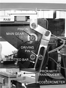
A biaxial accelerometer was used to measure the mechanical vibrations in the directions of the ram displacement and normal to the floor. The beginning of each working cycle of the mechanism was detected with a proximity transducer operating as a phase signal detector. The electrical motor controller provided the information of the electrical current by means of an analog output signal. The analog signals were recorded with a LabVIEW program and NI USB-6251 DAQ data acquisition system. Experiments were carried out with the motor operating at a speed of 600 rpm and data was acquired at a sampling rate of 10 kHz. The experimental rig is shown in Fig. 2. The picture inset at bottom left has been used to show details of the proximity and accelerometer transducers location.
Fig. 1Experimental quick return mechanism
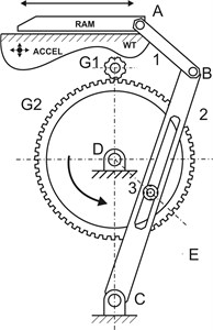
Fig. 2Experimental system layout
Rattling signal was post-processed with bandpass filters to isolate the characteristic frequencies of the phenomenon, and a local root-mean-square (RMS) estimation technique was used to obtain and index for detecting the rattle development and to establish threshold levels for rattling identification. The frequency function of the filter used is given by:
The bandpass of the filter is from B1 to B2, with a time delay td. And the root mean square (RMS) is given by:
The wavelet transform was used as a second processing technique for rattling development identification. In mathematical terms, a wavelet is a function ψ with zero average:
Which is dilated by a scale parameter s, and translated by u:
The continuous wavelet transform of a function f at the scale s and position u is computed by correlating f with a wavelet function:
Wavelet transforms can measure time-frequency variations of spectral components with a different time-frequency resolution. A wavelet transform correlates f with ψu,s.
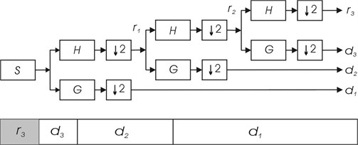
The implementation of the continuous wavelet transform is impractical because it consumes a significant amount of time and resources. The discrete wavelet transform DWT can be used to overcome this problem and it consists of a sub-band codification which can be implemented with a very high computational efficiency. Under this scheme, successive low-pass and high-pass filters are applied to the discrete time-domain signal as shown in Fig. 3. Low-pass filters are related to the scaling function while high-pass filters are related to the wavelet function, decomposing a signal in sub-bands that provide the low and high frequency information contained in a signal. In this work the 1-D Daubechies wavelet transform was used to decompose the signal and obtain the time-frequency information.
Fig. 3Discrete wavelet transform sub-band codification
3. Analysis and discussion of results
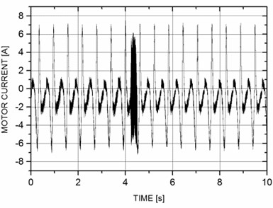
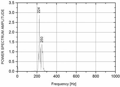
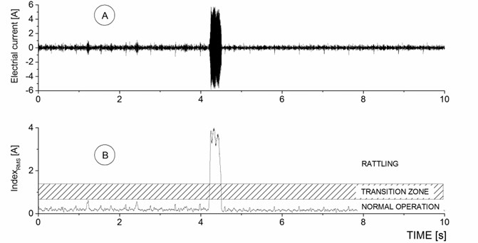
Mechanical vibrations data and electric motor current are shown in Figs. 4, 5. Although these signals are not directly related, some coincidences can be noticed. A regular change in amplitude can be observed for the entire length of the time recorded in the time-domain plots, showing the two-stroke cycle of the mechanism. A non-stationary event can also be distinguished at 4.5 s which corresponds to the instant when rattling occurs.
However, the frequency plots clearly show differences associated with the measured physical quantities. In the case of the acceleration records, mechanical vibrations are produced by the physical structure that supports the gear system. High frequency vibrations (mainly 800 Hz) are produced in response to the different modes of vibration of the mechanical elements when the quick-return mechanism is operated. However, the spectral analysis of the electrical current that drives the motor shows a peak at a frequency slightly larger than 200 Hz. This frequency is in concordance with the oscillatory phenomenon produced by the rattling of the gears.
Fig. 4Time-domain and frequency-domain of mechanical vibrations signal
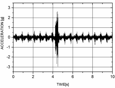
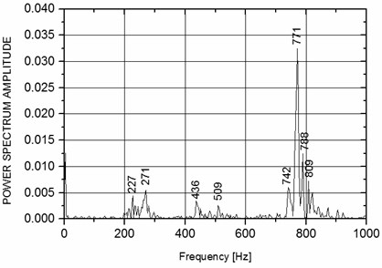
Fig. 5Time-domain and frequency-domain electrical motor current signal
Simple statistical analysis techniques for on-line detection of abnormal operating conditions in mechanical systems may be implemented. For the present work, a statistical technique for rattling development identification has been tested. This technique is based in the application of filters to the time-domain signals, and the construction of an index based on the RMS value of the filters output, according to the description given in the methodology section.
The time-domain signals have been passband-filtered with a center frequency set to the main excited frequencies. In correspondence to Figs. 4 and 5, frequencies were set to 771 Hz for the vibrations acceleration signal and 224 Hz for the electrical current signal. Finally, the RMS value of the signal was obtained. This process was applied to data packets comprising 0.02 s to include various rattling cycles. Results are shown in Figs. 6-7. Various operational regions have been defined to establish the limits of the threshold values for rattling identification. Three zones may be observed: The lower zone comprising the signal produced under normal operation, when rattling is not present; a transition zone, where the uncertainty in the rattling identification process may be considerable, depending on the signal of interest; and the upper zone, which defines the developed rattling state. The threshold value that indicates the boundary between normal operation and the transition zone is set to the maximum index value obtained from the signal under normal operation of the system, and the extent of the transition zone was set to the same value of the normal operation zone. This prevents that transitory signals result in false-positive identification.
For the case of the acceleration signal, rattling vibrations correspond to the structural frequencies that are also excited for each working cycle for normal operation of the mechanism. This results in index value variations that fall within the transition zone when rattling is present, with a significant uncertainty on the identification process. However, RMS values obtained from the electrical current signal are well defined with variations that fall far apart from the transition zone from the beginning to the end of the rattling occurrence. The result is a more reliable identification process technique based on the electrical current.
Fig. 6Rattling development detection from vibrations acceleration signal
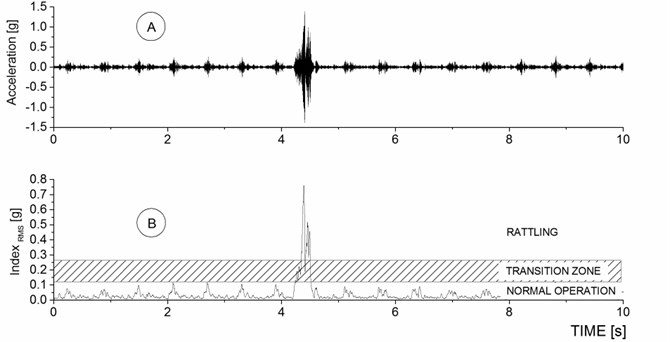
Fig. 7Rattling development detection from electrical current signal
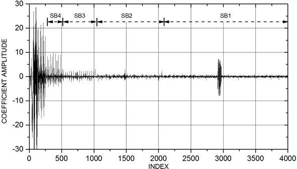
Since rattling can be considered a non-stationary phenomenon, a wavelet approach was also evaluated as a second method for detecting the rattling occurrence. Results obtained for the wavelet transform are shown in Figs. 8, 9, where the first four decomposition levels are depicted. Each level is labeled SB, and as a result of the procedure of transformation, it can be noticed that half of the data array is retained for each subsequent sublevel, evidencing the multi-resolution analysis, characteristic of the wavelet transform.
The wavelet transform coefficients for the mechanical vibrations acceleration are shown in Fig. 8. Each sub-band is associated with a frequency range of values, and wavelet coefficients grow in the middle of each sub-band when rattling occurs. Coefficients associated to rattling are present in all sub-bands due to the presence of a mechanical vibrations spectrum rich in low and high frequencies. Results for the electrical current signal transformation are shown in Fig. 9. In contrast to the mechanical vibrations, the electrical current frequencies are more clearly defined, particularly in relation to the rattling signal that can be observed within SB1 segment. Lower frequencies are present in response to the signal variations produced by the ram forward and backward movements.
The first four sub-bands, extracted from the transformed wavelet coefficients array, are shown in Fig. 10. High-amplitude coefficients in sub-band 1 clearly show the rattling occurrence, in comparison to the low-amplitude coefficients for the adjacent time segments where this phenomenon is not present. This plot shows that the wavelet method is suitable for identifying the gear rattle.
Fig. 8Wavelet transform of acceleration signal
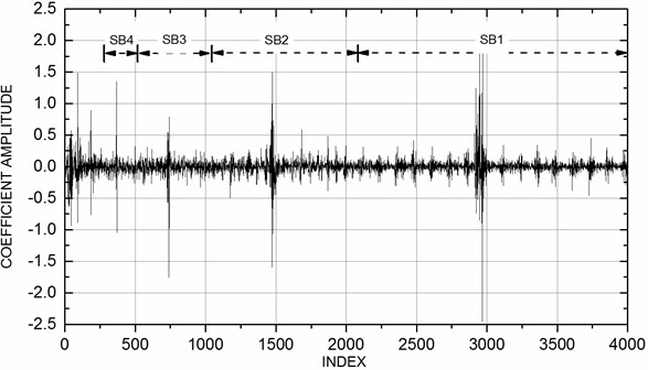
Fig. 9Wavelet transform of electrical motor current signal
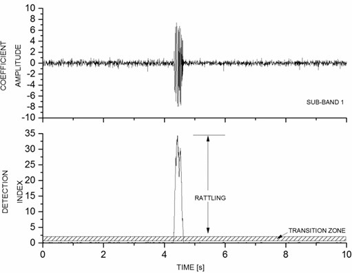
The RMS of the wavelet transform was processed to obtain the index and be able to compare both methodologies. Results are shown in Fig. 11. Significant differences arise with respect to Fig. 7. Wavelet processing offers a shorter transition zone, and a wider zone for the rattling developed state. It can also be noticed that the index values for normal operation of the system are almost imperceptible, due to the excellent results obtained by the sub-band coding of the wavelet approach in the isolation of the rattling. This means that the wavelet function is able to identify more precisely the rattling phenomenon, and it represents a more confident method of identification of the rattling development.
Fig. 10Four sub-bands extracted from the wavelet coefficients array
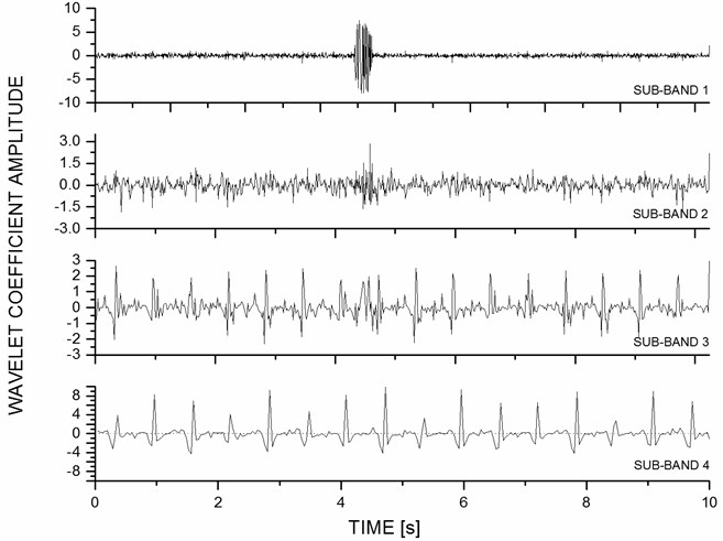
Fig. 11Rattling development detection with the wavelet approach
4. Conclusions
Two methodologies have been tested in a quick return mechanism for rattling development detection. A time-domain analysis method was compared to a time-frequency domain analysis method. The acceleration of the mechanical vibrations and the electric motor current were used as the source signals. It was found that, for both methods, the variations in the electrical current produced by the rattling offers a better way of identification of the gear-rattle, since frequencies are more localized in the spectrum. However, the wavelet approach, which consisted in the transformation of the signal to the time-frequency domain, and the extraction of the sub-band with the rattling occurrence, resulted in better discrimination indexes and therefore a superior technique for rattling detection. This represents a very useful tool for on-line detection of rattling in mechanical systems, since the wavelet transform can be implemented with a high-computational efficiency.
References
-
Al-Ghamd A. M., Mba D. A comparative experimental study on the use of acoustic emission and vibration analysis for bearing defect identification and estimation of defect size. Mechanical Systems and Signal Processing, Vol. 20, 2006, p. 1537-1571.
-
Loutridis S. J. Damage detection in gear systems using empirical mode decomposition. Engineering Structures, Vol. 26, 2004, p. 1833-1841.
-
Wang W., Kanneg D. An integrated classifier for gear system monitoring. Mechanical Systems and Signal Processing, Vol. 23, 2009, p. 1298-1312.
-
Gaberson H. A. The use of wavelets for analyzing transient machinery vibration. Sound and Vibration, Vol. 36, 2002, p. 12-17.
-
Dalpiaz G., Rivola A., Rubini R. Effectiveness and sensitivity of vibration processing techniques for local fault detection in gears. Mechanical Systems and Signal Processing, Vol. 14, 2000, p. 387-412.
-
Peng Z. K., Chu F. L. Application of the wavelet transform in machine condition monitoring and fault diagnostics: a review with bibliography. Mechanical Systems and Signal Processing, Vol. 18, 2004, p. 199-221.
-
Kunpeng Z., San W. Y., Soon H. G. Wavelet analysis of sensor signals for tool condition monitoring: a review and some new results. International Journal of Machine Tools and Manufacture, Vol. 49, 2009, p. 537-553.
-
Zhen L., Zhengjia H., Yanyang Z., Yanxue W. Customized wavelet denoising using intra- and inter-scale dependency for bearing fault detection. Journal of Sound and Vibration, Vol. 313, 2008, p. 342-359.
-
Jafarizadeh M. A., Hassannejad R., Ettefagh M. M., Chitsaz S. Asynchronous input gear damage diagnosis using time averaging and wavelet filtering. Mechanical Systems and Signal Processing, Vol. 22, 2008, p. 172-201.
-
Shao R., Hu W., Wang Y., Qi X. The fault feature extraction and classification of gear using principal component analysis and kernel principal component analysis based on the wavelet packet transform. Measurement, Vol. 54, 2014, p. 118-132.
-
Halim E. B., Choudhury M. A. A. S., Shah S. L., Zuo M. J. Time domain averaging across all scales: a novel method for detection of gearbox faults. Mechanical Systems and Signal Processing, Vol. 22, 2008, p. 261-278.
-
Combet F., Gelman L., LaPayne G. Novel detection of local tooth damage in gears by the wavelet bicoherence. Mechanical Systems and Signal Processing, Vol. 26, 2012, p. 218-228.
-
Loutridis S. J. Gear failure prediction using multiscale local statistics. Engineering Structures, Vol. 30, 2008, p. 1214-1223.
-
Eftekharnejad B., Addali A., Mba D. Shaft crack diagnostics in a gearbox. Applied Acoustics, Vol. 73, 2012, p. 723-733.
-
Lei Y., Zuo M. J., He Z., Zi Y. A multidimensional hybrid intelligent method for gear fault diagnosis. Expert Systems with Applications, Vol. 37, 2010, p. 1419-1430.
-
Loutridis S., Trochidis A. Classification of gear faults using Hoelder exponents. Mechanical Systems and Signal Processing, Vol. 18, 2004, p. 1009-1030.
-
Rubio E., Ramírez G. Experimental characterization of gear-rattle in a quick-return mechanism. Journal of Vibroengineering, Vol. 16, 2014, p. 2118-2122.
