Abstract
In this paper, the holospectrum is introduced to analyse bearing cage behaviour. Through data fusion on radial vibration displacements, one type of frequency domain analysis, holospectrum, is applied to reflect the detailed characteristics of cage dynamic behaviour. Several typical bearing cage running conditions, such as unbalance, misalignment, impact and friction, are discussed in the investigation, and the corresponding characteristics in the holospectrum are identified. The holospectrum has intuitive and understandable characteristics for the analysis of cage whirling motion. The experimental results show that the holospectrum analysis has the potential to deeply assess bearing cage behaviour.
1. Introduction
Various impact forces, friction forces and the action of lubricating oil on a ball bearing cage lead to a more complicated cage orbit. If the design parameters of the cage are not reasonable and error occurs in the manufacture of the cage, an instable cage orbit will occur under running conditions; it will affect the lifetime of the bearing cage. Therefore, the detection and analysis of the cage orbit is significant to recognize the cage behaviour of ball bearings.
To observe the cage orbit of ball bearings, scientists [1-3] have presented several detection methods. Their works concentrate in the area of the stability of the bearing cage orbit. However, little research concerns the detailed dynamic characteristics of a cage orbit with data fusion.
In this paper, holospectrum, an analysis tool from Data Fusion, will be used to recognize the running and health conditions of bearing cages. The study is arranged as follows: (1) the laser technology used in cage behaviour detection; (2) the holospectrum constructed from a set of experimental data; (3) various characteristics used in the analysis of cage behaviour.
2. Cage behaviour detection
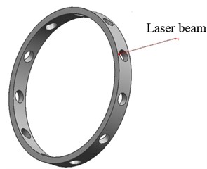
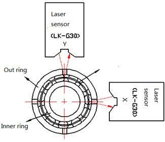
Cage behaviour detection is realized by two laser sensors, as shown in Fig. 1, which are perpendicularly installed in the same plane. A laser, a LK-G30 model made in Keyence, is used, and the pot of laser light is approximately 20 µm; it is extremely small as to illuminate on the edge of the cage. The laser beam passes through the smaller gaps in the outer ring of the bearing, and the laser sensors can pick up the vibration displacement from a surface of the rotating cage. The resolution of the laser detection is 0.05 µm, and the measurement error is approximately 0.03 %. Therefore, when a ball bearing is running, the laser technology can directly be used in non-contact measurement for the cage vibration, and the detecting data are of higher accuracy.
A 7002/P4 ball bearing is used as a test object, and its cage is made of phenolic textolite. Two gaps perpendicular to each other are formed by the manufacturing technology of electric spark cutting. As a result, the formed holes will not disturb the bearing working conditions, and the laser beams can pass through the gaps and illuminate on the edge of the cage. The schematic of cage behaviour detection with the laser is shown in Fig. 1(b).
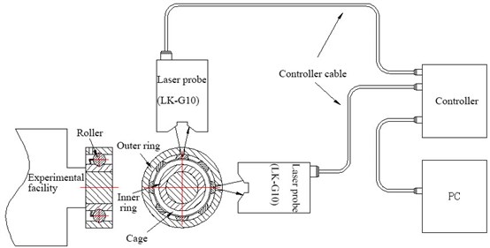
As shown in Fig. 2, a cage behaviour detection system consists of an Andrew bearing test drive, laser sensors and a computer-based data acquisition system. When a ball bearing is installed on the Andrew bearing test drive, an axial force will be applied to an outer ring of the bearing. Then, an inner ring of bearing is driven at the rotating speed of 1800 rpm.
The cage vibration displacement signals are synchronously picked up in the X and Y directions. The sampling frequency is set to 10 kHz in the data acquisition, and the length of data is 65536. To overcome the random disturbance on the laser detection from the lubricating oil film, the low pass band filter is set with a cut-off frequency of 100 Hz.
Fig. 1Principle of cage behaviour detection
a) Laser beam illuminating
b) Laser beams perpendicular to the edge of cage and each other
Fig. 2Cage behaviour detection system
2.1. Time record of cage vibration
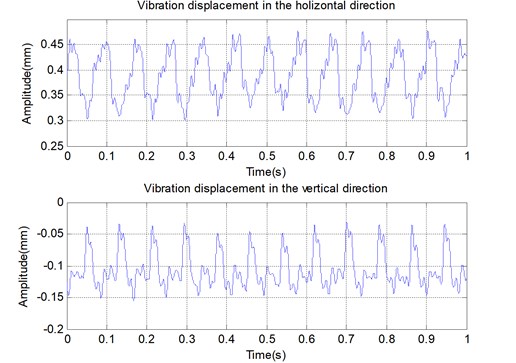
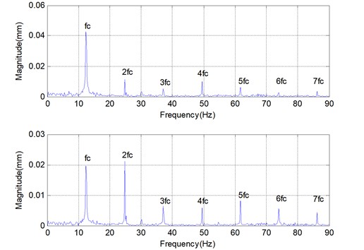
Fig. 3(a) is the time record of the cage vibration displacement in the X and Y directions when an axial force of 22.23 N is loaded, where the direct component in the record is caused by initial distance of the laser sensor. Fig. 3(b) is the corresponding spectrum of the cage vibration displacement.
Through calculating the characteristic frequency, the obtained frequency of inner ring rotation is 30 Hz, and the characteristic frequency of the cage fc=11.96 Hz. The harmonic components can be recognized in the spectrum diagram by analysing the geometrical parameters and the rotational speed. It is well seen that the magnitude of the first characteristic frequency is the largest in the given spectrum.
2.2. Cage orbit description
Imaging the cage orbit is described as a complex function z, that is:
where x and y correspond to the vibrational displacement of cage in the X and Y directions, respectively.
Fig. 3Vibration displacement of cage and its spectrum
a) Vibration displacement of the cage in the X and Y directions (1 second time record)
b) Spectrum of the vibration displacement
Fig. 4Cage orbit with a symbol of “8” without axial load
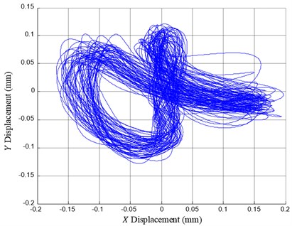
As shown in Fig. 4, the cage orbit can be synthesized based on Eq. (1). The cage dynamic behaviour can recognized if the cage is in a health running condition. In fact, the given cage orbit is one of the running conditions, and it follows the shape of an “8”, caused by misalignment of the cage axes.
3. Holospectrum
The cage orbit is one of the reliable conditions for the evaluation of cage dynamic behaviour. Although, this technology has being used in practice, there are still a number of weak points. For example, the diagram of the cage orbit mixes all of the vibration components, and the correlation of the vibrations in the horizontal and vertical directions cannot be explored in each harmonic component.
The 2D-holospectrum is the spectrum analysis technique that synthesizes the information of the phase, amplitude, frequency and rotating direction by two probes perpendicularly mounted on each measuring section [3]. It is a decomposition of the orbit on the basis of the cage characteristic frequency. If the corresponding FFT spectra of the vibration signals are combined properly, a series of ellipses, circles or straight lines with arrows in a plan will be obtained. From the holospectrum, the condition of the running cage can be obtained, and mechanical back draw can be diagnosed, such as unbalance, misalignment, friction and the impact between the cage and the ring.
3.1. Holospectrum
When Fourier transform is carried out on the bearing cage orbit z in Eq. (1), the complex function z can be decomposed into many harmonic components:
=∑nj=1cjei(ωjt+ϕj)+dje-i(ωjt++ϕj),
where cj=(aj+bj)/2, dj=(aj-bj)/2, and these values correspond to the magnitude of the vectors rotating in the positive and negative direction, respectively.
Then, using one harmonic component:
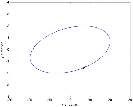
the shape of an ellipse or straight line can be formed. In Fig. 5, the cage whirling motion of the component ωj is represented. Taking j from 1 to n, an entire diagram of the holospectrum is constructed, and the different order of cage whirling motions can be clearly depicted.
Fig. 5Cage orbit of the component ωj
3.2. Whirling direction
However, there is a directional problem of the cage whirling motion. When the direction of the cage whirling orbit is coincident with the bearing rotation, it is called the positive precession. Conversely, it is called the anti-precession when the direction of the cage whirling orbit is not coincident with the bearing motion.
From the form of a complex exponent:
and the direction of the cage whirling motion is determined as the positive precession in the case of cj>dj; it is determined as the anti-precession in the case of cj<dj.
As shown in Fig. 6, the cage whirling motion corresponds to the case presented in Fig. 4. The diagram of the holospectrum combining the whirling direction is more significant in research regarding the cage dynamic behaviour. The horizontal ordinate indicates the times of the cage characteristic frequency, and the signs of “–” and “+” are the direction of the cage precession. The dimension of the long axis of the ellipse or straight line reflects the energy of the cage orbit with component ωj. Through observation on the holospectrum, the cage orbit of the component ωj, and the cage whirling direction may both be seen.
Fig. 6Holospectrum of cage whirling motion

3.3. Correction technology
The parameter estimation with higher accuracy in Eq. (4) is assurance in the reconstructing of the holospectrum reflected in the cage dynamic behaviour. Due to data acquisition for cage vibration displacement without any tacho reference, the vibration wave of cage and its harmonics are not generally integers in the finite length data, which causes the parameters of the estimation error of aj, bj, ψrj and ψij on the FFT algorithm. Therefore, such parameter estimations cannot be directly used in reconstruction of the holospectrum. To obtain the parametric estimation with higher accuracy, the correction technology [4] of the amplitude and phase of each component is needed before the holospectrum is reconstructed based on the sampling data.
By analysing the windowing vibration data, the barycentre of the spectral lines in the main lobe is used to obtain the coordinate of the spectrum peak, and the frequency deviation and phase distortion of component are identified. Then, the leakage induced error is corrected in the improved FFT algorithm, and the parameter estimations are obtained for the harmonic components. For the finite length data with discrete spectra, the correction method has been shown to be both accurate and easy to use in practice [5, 6]. Additionally, the bilateral spectrum should be used in signal processing to determine the direction of the cage whirling motion.
3.4. Noise pollution
Noise pollution cannot be avoided in the data measurement, and it will affect the estimation accuracy of the amplitude and phase when reconstructing the holospectrum. Considering a discrete signal x(i) mixed with noise n(i) and the ratio of signal and noise as 1:1, let a discrete signal be:
where the signal frequency f= 50 Hz.
In the simulation, the length of the time series is 2048, which is obtained under a sampling frequency 2048 Hz. The noise is subjected to the Gauss distribution. Due to the noise effect, a different sample y(i) has a different parameter estimation result. Assuming the estimation results could be seen as an approximately normal distribution and a sample of the 50000 time series is involved in the statistic test, the standard deviation of the amplitude and phase estimation will correspond to 0.2212 and 1.2644, respectively.
To improve the accuracy of the parameter estimations, the mean value of the parameter estimation from 16 time series can be used instead of the single sample estimation. As a result, the error of the amplitude estimation is less than 1 %, and the error of the phase estimation is less than 1 degree in the given ratio of signal and noise. By use of the mean value of the estimation parameters, the effect of noise pollution can be reduced in the holospectrum of the cage orbit.
4. Application
The cage running condition can be recognized by analysing the characteristics in the holospectrum of the cage orbit, which can be used in cage quality assurance. Some manufacture and assembling problems with the cage, such as unbalance, misalignment, static and dynamic impact, etc., will affect the orbit of the cage whirling motion, and their actions will also be reflected in the characteristics of the holospectrum.
Fig. 7Holospectrum when a 22.3 N force is loaded in an axial direction
a) Cage obit

b) Holospectrum
4.1. Unbalance
Due to a cage assembled among several balls, residual unbalance is inevitable in the running bearing. Unbalance makes the mass centre of the cage far from the bearing centre. The characteristic frequency of unbalance corresponds to the frequency of the cage rotation, which is called as the first order characteristic frequency 1x. So, the unbalance characteristic can be recognized in the holospectrum by analysing the circle shape corresponding to the first-order characteristic. More unbalance, larger whirling motion, and larger circle shape all are seen in the first order characteristic. If the cage is in an uneven support in the perpendicular direction, the unbalance characteristic will be changed to an ellipse in the holospectrum. In the extreme case, the unbalance characteristic will be seen in a straight line.
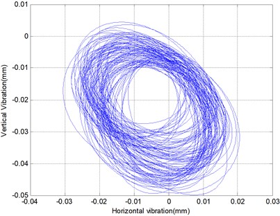
Fig. 7 is the holospectrum of the cage orbit where a 22.23 N force is loaded in the axial direction. Fig. 8 is another case where an 88.92 N force is loaded in the axis direction. It is obvious that the characteristic of unbalance in the later example is smaller than in the former. The axial force causes the unbalance amount of the cage to become smaller.
Fig. 8Holospectrum when an 88.92 N force is loaded in an axial direction
a) Cage obit

b) Holospectrum
4.2. Misalignment
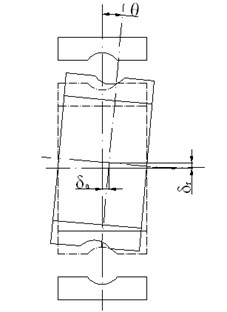
When the axis of the running cage is not parallel to the axis of the bearing, misalignment will occur in the running cage, and it will be reflected in the second order characteristics in the holospectrum. Fig. 9 is a case of misalignment caused by an 88.92 N asymmetric axial force placed on the outer ring of the bearing. In general, the reasons for misalignment are related to cage mass asymmetry, a large clearance between the ball and pocket and an asymmetric axial force on the outer ring of the bearing. This mechanical back draw is concerned with design, machining and the assembly of the bearing cage.
As shown in Fig. 6 where no axial force is exerted on the ball bearing, the cage also runs with misalignment, as is the case corresponding to Fig. 4. The second and fourth order characteristics in the holospectrum obviously appear as a result of a large clearance between the ball and pocket without an axial force on the ball bearing.
4.3. Impact and friction
There are impact and friction forces between the cage and balls and the cage and the outer or inner rings in the running bearing. The impact and friction forces will excite the cage vibration with a high order harmonic. The action of the impact and friction will induce the high order characteristic in the holospectrum.
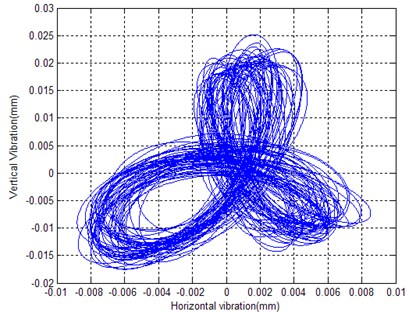
Fig. 9 shows the holospectrum in the case of misalignment. Due to an asymmetric axial load, serious impact will occur in the running cage, which leads a rich higher order characteristic in the holospectrum. Furthermore, the impact and friction also exist in the case of no loading, as shown in Fig. 6.
Fig. 9Holospectrum when an 88.92 N asymmetric force is loaded on the outer ring
a) Misalignment cage
b) Cage obit

c) Holospectrum
4.4. Characteristic summery
To easily recognize the health condition of the running cage, the basic characteristics in the holospectrum are summarized in Table 1. The bearing cage dynamic behaviour is quickly recognized from these results, and the quality of cage manufacture can be readily diagnosed.
Table 1Cage running condition and characteristics in the holospectrum
Running condition | Characteristics in holospectrum |
Unbalance | The 1st order |
Misalignment | The 2nd, 4th, 6th order |
Impact and friction | The 1st and higher order |
5. Discussion
The holospectrum is constructed from the cage orbit base on the FFT algorithm, and it will average the signal magnitude and produce the mean value in the result. It cannot be adapted to the case of time variation.
5.1. Bi-stable state
There is a dynamic characteristic of the bi-stable state in the cage orbit. The concept of the bi-state comes from a state jumping in electronics. When something exciting acts on the cage, the cage dynamic behaviour will jump from one state to another and will run stably for a moment. The nonlinear action of the cage and balls is the physical reason of this dynamic behaviour, and it causes cage eddy from one state and another as well as causes the vibration amplitude to change.
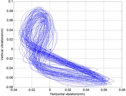
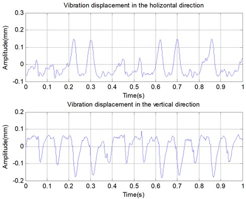
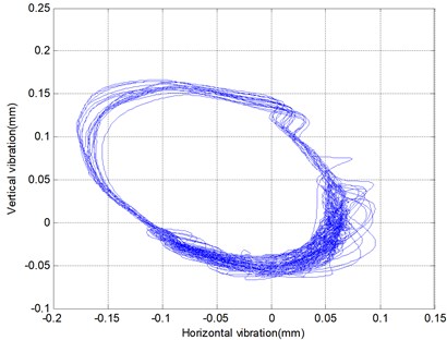
As shown in Fig. 10(a), there is a bi-stable state in the vibration displacement, and the amplitude difference is almost double. The cage orbit occurs in the state of unstable, running around an ellipse moment and oscillating around the arc of the ellipse. The detailed orbit can be seen in Fig. 10(b), and the phenomenon of bi-stable state is obvious in the cage orbit.
When the bi-stable state in the cage orbit is decomposed to the holospectrum, as shown in Fig. 10(c), the characteristic of the bi-stable state will be lost and no characteristic of the bi-stable state will occur in the holospectrum. In this situation, it can be easy to understand the cage dynamic behaviour by only relying on an original cage orbit.
Fig. 10Bi-stable state of the cage orbit
a) Vibration displacement in the X and Y direction
b) Cage orbit with an oscillation arc

c) Bi-stable state characteristic in the holospectrum
5.2. Shape error
When shape error exists in the cage, its characteristics will be reflected in the holospectrum. For example, the cage with an elliptical shape will cause the second order characteristic in the holospectrum. This misread should be avoided in the analysis of cage behaviour by selecting the qualified bearing cage as a test sample.
6. Conclusions
The holospectrum is an assemblage of the orbit of different characteristic frequencies, and it is a type of data fusion technology that synthesizes the information of the phase, amplitude, frequency and rotating direction. The holospectrum consists of a series of ellipses, circles or straight lines with arrows in a plan, the dimension of the long elliptical axis reflects the corresponding orbit energy, and the arrow symbols indicate the whirling direction. The holospectrum is effective to study bearing cage behaviour in each harmonic component, and its characteristics can reflect the running conditions of cage orbit. Some basic characteristics in the holospectrum can successfully be applied to recognize cage dynamic behaviour, such as unbalance, misalignment, impact and friction.
The holospectrum on the improved Fourier transform algorithm is easy construct through signal synthesis, and its characteristics are intuitive and understandable in analysing cage dynamic behaviour. Therefore, holospectrum can provide a new clue to study cage dynamic behaviour in bearing manufacture quality assurance. This approach is adapted to analyse a stable cage orbit, however, at least for one moment.
References
-
Kingsbury E. P. Ball motion in angular contact bearings. Wear, Issue 11, 1968, p. 41-50.
-
Tomoya Sakaguchi, Kazuyoshi Harada Dynamic analysis of cage behavior in a tapered roller bearing. ASME Journal of Tribology, Vol. 128, Issue 3, 2006, p. 604-611.
-
Qu Liangsheng, Liu Xiong, Chen Yaodong Discovering the holospectrum. Noise and Vibration Control Worldwide, Vol. 20, Issue 2, 1989, p. 58-62.
-
Huang D. Phase error in fast Fourier-transform analysis. Mechanical Systems and Signal Processing, Vol. 9, Issue 2, 1995, p. 113-118.
-
Agrež D. Improving phase estimation with leakage minimization. IEEE Transactions on Instrumentation and Measurement, Vol. 54, Issue 4, 2005, p. 1347-1353.
-
Xie M., Ding K. Corrections for frequency, amplitude and phase in a fast Fourier transform of a harmonic signal. Mechanical Systems and Signal Processing, Vol. 10, Issue 2, 1996, p. 211-221.
About this article
The authors would like to acknowledge the support of the Research Foundation of Shanghai Municipal Government (Grant No. 14111103703).
