Abstract
The aero-elastic response of the blades is affected by the structure style of the rotor hub. The fatigue life of the structure and the vibration level of the entire helicopter are directly affected by the aero-elastic response of the blades. Therefore, its vibration characteristics and aero-elastic response shall be considered emphatically during structure design. The flapping and lead-lag characteristics of the rotor hub were tested experimentally in the paper. It was shown in results that a big vibration displacement was generated from the rotor hub under two working conditions. However, a larger vibration displacement was generated from the flapping than that of the lead-lag. Therefore, it is necessary to conduct optimization design to the rotor hub. Analysis was carried out to aero-elastic dynamics of bearing-less rotor. Afterwards, a multi-objective optimization model for reducing vibration and aero-elastic dynamic of bearing-less rotor was built. Pareto front of multi-objective optimization design for bearing-less rotor was acquired by Genetic Algorithm (GA). To reduce the optimization burdens, the aero-elastic dynamic model was replaced by Radial Basis Function (RBF) model during the optimization. To decrease the computational costs, the sample points with the minimum point set center deviation of the current surrogate model were added gradually. Meanwhile, the design schemes of Pareto front were ranked by TOPSIS to select the design scheme with the maximum satisfaction. Comparison was carried out between the rotor design scheme with the maximum satisfaction and the unoptimized model in terms of modal frequency, modal shape and vibration load of the hub. The results showed that the dynamic performance of the optimized rotor was improved significantly. The method in this paper also provided an important reference for multi-objective optimization of aero-elastic dynamic and engineering design of other rotors.
1. Introduction
The inherent weakness of hinge-less rotor is overcome by bearing-less rotor and its hub system. Various advantages of the other rotor hub are also integrated by them. Its advanced technology and performance run ahead of the other rotor hub. The rotor hub system of helicopters is always under the working condition of high-speed rotation. The aero-elastic response of the blades is affected by its structural shape. The fatigue life of the structure and the vibration level of the entire helicopter are directly affected by the aero-elastic response of the blades. Therefore, its vibration characteristics and aero-elastic response shall be considered emphatically during structure design. It’s of great significance to carry out reduction vibration and aero-elastic dynamic optimization for the bearing-less rotor hub.
The application of the optimization technique is mature in other fields. Nevertheless, it’s immature in helicopter, particularly aero-elastic dynamic design of the rotor hub. Currently, with the continuous improvement of optimization technique and optimization strategy, attention has been paid to the rotor hub. The current optimization in aero-elastic dynamic design of the rotor hub are mainly reflected in the following four aspects: a) the precise aero-elastic dynamic analysis model was researched [1-3], b) the reasonable reduction vibration and aero-elastic dynamic design for the rotor hub were conducted [4-5], c) optimization algorithms with global convergence performance were proposed [6-7], d) the surrogate model which can meet the engineering requirements was used during optimization [8-9].
The flapping and lead-lag characteristics of the rotor hub were tested experimentally in the paper. It was shown in results that a big vibration displacement was generated from the rotor hub under two working conditions. However, a larger vibration displacement was generated from the flapping than that of the lead-lag. Therefore, it is necessary to conduct optimization design to the rotor hub. Analysis was carried out to aero-elastic dynamics of bearing-less rotor. Afterwards, a multi-objective optimization model for reducing vibration and aero-elastic dynamic of bearing-less rotor was built. Pareto front of multi-objective optimization design for bearing-less rotor was acquired by Genetic Algorithm (GA). To reduce the optimization burdens, the aero-elastic dynamic model was replaced by Radial Basis Function (RBF) model during the optimization. To decrease the computational costs, the sample points with the minimum point set center deviation of the current surrogate model were added gradually. Meanwhile, the design schemes of Pareto front were ranked by TOPSIS to select the design scheme with the maximum satisfaction. Comparison was carried out between the rotor design scheme with the maximum satisfaction and the unoptimized model in terms of modal frequency, modal shape and vibration load of the hub. The results showed that the dynamic performance of the optimized rotor was improved significantly. The method in this paper also provided a important reference for multi-objective optimization of aero-elastic dynamic and engineering design of other rotors.
2. Experimental test of vibration for the flexible beam
During the experiment of the flexible beam, a dividing head which was installed on the horizontal platform was used to fix one end of the flexible beam. The other end of the flexible beam was loaded to test the displacement of the sectional point on the flexible beam.
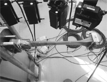
During the experiment, four-level loading was carried out by steps. Loading manners were divided into 0 kg, 4 kg, 6 kg, 8 kg, 6 kg, 4 kg and 0 kg. The relative change of the displacement for each test point under each state was collected for 3 times. The mean value was finally obtained. The experiment of the flexible beam under the flapping and lead-lag states was shown in Fig. 1 and Fig. 2.
Fig. 1Diagram of loading experiment in flapping vibration direction
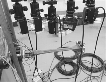
Fig. 2Diagram of loading experiment in lead-lag vibration direction
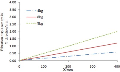
The experimental results of the flexible beam were shown in Fig. 3 and Fig. 4. In the figures, X axis stood for the position of the axial direction for the flexible beam, while Y axis stood for the relative change of the vibration displacement. The relative change of the vibration displacement was the relative value between the actual displacement and the zero-load displacement. The results in Fig. 3 and Fig. 4 showed that the vibration displacement was relatively big in the flapping direction. Therefore, during the practical engineering, it is necessary to reduce the load in the flapping vibration direction for the flexible beam so as to improve the vibration characteristics of the rotor hub system.
Fig. 3The experimental result of the flexible beam in flapping vibration direction
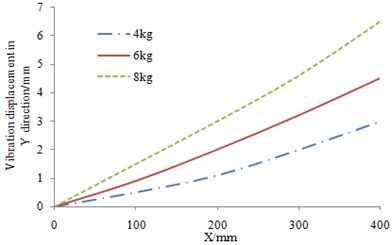
Fig. 4The experimental result of the flexible beam in lead-lag vibration direction
3. Analysis model of the rotor hub
The largest difference between the bearing-less rotor hub and the articulated rotor hub is that the flexible beam is adopted to replace the flapping, lead-lag and pitch hinge of the articulated rotor hub. To control the pitch motion of the blades and improve the efficiency, a torque tube is connected at the joint between the blade and the flexible beam. To realize the effect, the following problems shall be solved.
1) Displacement at the joint of the torque tube, the flexible beam and the blade should be coincident as follows:
w't=w'f=w'b,ϕt=ϕf=ϕb,
u, v, w were the displacement along x, y, z directions in the coordinated system as shown in Fig. 5. The subscripts t, f and b represented the torque tube, the flexible beam and the blade, respectively. v', w' were velocity in corresponding directions. ϕ was the rotary displacement around x axis. ηt was the offset of the torque tube center and ηf is the offset of the flexible beam center. The pitch motion of the blade was transmitted to the pitch link by the flexible beam. The torque tube was rigid. The pitch link was elastically connected on the torque tube and the control system as shown in Fig. 5(a). Due to the elastic effect of the pitch link, the strain energy caused by the link was added on the element which is on the end of the torque tube as follows:
where Kp was the spring stiffness caused by the pitch link. d was the distance between the pitch link and the torque tube center. wp was the displacement caused by elasticity of the pitch link and the control system. The diagram of the joint structure between the blades and the torque tube was shown in Fig. 5(b).
2) Equivalent treatment for the double beams:
(EIy)e=(EIy)1+(EIy)2,(GJ)e=(GJ)1+(GJ)2+12(η1-η2)2L2f(EIy)1(EIy)2(EIy)1+(EIy)2,
me=m1+m2,
EA was the axial tensile stiffness. EIy was the flapping stiffness. EIz was the lead-lag stiffness. GJ was the torsional stiffness. m was mass of unit length. The torque tube and the flexible beam were connected to the end of the blades. The subscripts e, 1 and 2 represented the equivalent beam, the flexible beam and the torque tube, respectively. Lf was the length of the flexible beam.
Fig. 5Diagram of the model for the bearing-less rotor hub system
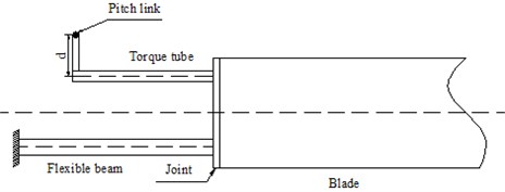
a) Structure diagram of the rotor hub system
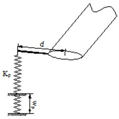
b) Diagram of joint structure between the pitch link and the torque tube
3) Parameters of the flexible beam for the bearing-less rotor hub should meet the following conditions:
w't=0,ϕp=ϕp0,ϕt=ϕf.
In the equation, the detailed description of each parameter can refer to Eq. (1).
4. Vibration characteristic optimization of the rotor hub based on GA
4.1. Mathematical model of optimization for the rotor hub
The key to optimization design of the bearing-less rotor hub is the flexible beam. Aero-elastic cutting was carried out for the flexible beam. Therefore, the requirement of the dynamic characteristic for the bearing-less rotor hub could be satisfied. The flexible beam structure was shown in Fig. 6(a), and its structural section was shown in Fig. 6(b).
Fig. 6Diagram of the flexible beam

a) Diagram of the flexible beam structure
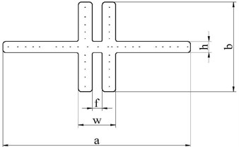
b) Diagram of the typical section for the flexible beam
The flexible beam was constituted of five parts. Part I was the root joint section. Part II was the transition section. Part III was the torsional deformation section which bears the torsional deformation motion of the blade. Part IV was transmission section of the torsional deformation. Part V was joint section of the blades. The ply angle of the composite material for the flexible beam at the minimum section III was 00. Optimization of the section shape was the key during optimization. The ply angles of the flexible beam at other four parts were random. Aero-elastic cutting was realized by the optimization of the ply angles. The aero-elastic cutting for the entire flexible beam could be completed by optimizing the five sections of the flexible beam. In this way, the dynamic characteristics of the entire rotor blade could meet the design requirements. Multi-objective optimization for reduction vibration of the rotor hub could be realized. The mathematical model was as follows:
s.t.ak<0,
gA≤0,σ≤σ0,ωFkL≤ωFk≤ωFkU,ωLkL≤ωLk≤ωLkU,
ωθkL≤ωθk≤ωθkU,viL≤vi≤viU.
The objective function in Eq. (5) was divided into two types as follows.
1) The horizontal force FY and the vertical force FZ of the rotor hub were the minimized vibration loads. They were calculated by the following equation:
where subscripts R and H stood for a rotary coordinate system (non-transformed blade) and a fixed coordinate system, respectively. TTC was a transfer matrix from the non-transformed blade to the fixed coordinate system.
2) Wwas the minimized blade mass. The blade mass included both structural and non-structural masses. They were calculated by the following equation:
In the equation, ρi was the linear density of the i unit and Li was the length of the i unit.
The constraint function in Eq. (5) was explained in details as follows.
1) αk was the modal stability coefficient of the k order:
λRk, λIk were the real part and imaginary part of the k order modal characteristic, respectively. T was the number of circles.
2) gA was the rotary inertia of the blades:
mi was the dimensionless unit mass of the i unit for the blades. xi was the distance from the left end point of the i unit to the blade root. RA was the minimum rotational inertia ratio. The minimum rotational inertia ratio was the ratio of the rotational inertia of the blades in the calculation model to the reference rotational inertia.
3) σ was the dynamic reaction at the blade end:
where, FR was the centrifugal force which was generated from blade motions. AR was the sectional area with maximum stress level, and σ0 was the reference stress level of the blades.
4) In Eq. (5), ωFk was the k order flapping frequency. ωLk was the k order lead-lag frequency. ωθk was the k order pitch frequency. The low right subscripts L and U stood for the change scope of lower limit and upper limit for the constraint function. In order to avoid resonance and reduce vibration loads which would be transmitted to the rotor hub due to the lead-lag and flapping motions of the blades in a helicopter, the base-order inherent frequency should be kept within a certain scope as follows:
4.5≤ωF2≤5.2,2.5≤ωL2≤3.0,12≤ωθ2≤13.2.
4.2. The optimization of the rotor hub based on GA
Genetic algorithm was used in the paper for optimization design of the rotor hub. Its necessity can be explained from the following aspects.
1) Multiple constraint variables were considered in the paper, and then the multi-objective optimization design was carried out to the rotor hub of a helicopter. An absolute optimal solution could hardly be found for the multi-objective optimization problem. In general, multiple Pareto optimal solutions are obtained and form an assembly. In addition, evolutionary operations are carried out to the whole group by genetic algorithm, and an assembly of individuals is processed. Because of such similarity, genetic algorithm becomes an effective method to obtain Pareto optimal solution of a multi-objective problem. It was widely used in the aerospace field. For example, the genetic algorithm was used by Liu to redesign aerodynamic appearance of a rotor blade, and experiments were conducted to the optimized structure [10]. As a result, effectiveness of genetic algorithm in multi-objective optimization of a helicopter was verified. Genetic algorithm was also used by Crossley to research the multi-objective optimization design problem with the minimum rotor mass and required power. Parameters like discrete element stiffness were taken as the design variables [11].
2) If the finite element method is directly used for calculation of the rotor hub, calculation time would be long and cost would be high due to the huge mesh quantity. In this paper, the finite element method was replaced by RBF (radial basis function) surrogate model during the numerical calculation of the rotor hub. In this way, calculation time was saved a lot in comparison with the finite element method. In addition, RBF surrogate model is characterized by whole and partial estimation. It is a surrogate model with good flexibility, simple structure, relatively less calculation amount and relatively high efficiency. The surrogate model cannot be integrated with the deterministic algorithm yet. In most of the current researches, the surrogate model is combined with genetic algorithm.
3) Research in this paper was carried out based on ISIGHT software. In this software, processes like genetic algorithm and surrogate model are integrated. Only some parameters in the software are required to be modified. Too much time needs not to be spent on programming and calculation. In this way, calculation efficiency is increased. Such software has been widely used.
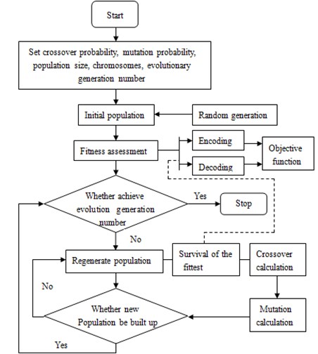
Based on the mentioned analysis, genetic algorithm was used in the paper for structure optimization of the rotor hub. The basic flow was shown in Fig. 7.
Realization of the optimization design for the rotor hub based on genetic algorithm was as follows.
1) Chromosome coding. Before searching, the target function was encoded into a binary string with fixed length, and such string was a chromosome. Different search points in the search space were constituted of different combinations of these strings.
2) Generation of the initial population. Size of the initial population was set to be 30.
3) Fitness calculation. Convergence rate of genetic algorithm and whether an optimal solution can be found are directly influenced by fitness. In this paper, negatives of the target function values were taken as the fitness values.
4) Selection. Individuals which showed relatively stable fitness during evolution were selected.
5) Crossover. Some chromosomes among 30 individuals were exchanged under a probability. 30 new individuals were then generated. The crossover probability was set to be 0.9.
6) Mutation. Mutation was carried out to the selected 30 individuals according to the given probability. A new generation group was then formed. The mutation probability in this paper was 0.05.
7) Judgment. Whether the new generation group could satisfy constraint conditions was judged. If the conditions could be satisfied, the operation would be stopped, otherwise, step 3 would be continued.
Fig. 7Basic flow of genetic algorithm
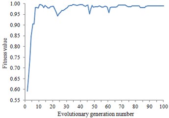
Fitness was taken as an evaluation index for convergence of genetic algorithm. The change curve of fitness with the evolutionary generation number during optimization was shown in Fig. 8. According to this figure, the fitness has tended to be stabilized when the evolution developed to the 100th generation. As a result, the calculation results were convergent.
Fig. 8Change curve of fitness with the evolutionary generation number
During the optimization process, RBF surrogate model of the aero-elastic dynamic for the rotor hub was built in order to reduce optimization burdens. RBF surrogate model is a kind of function. In the function, Euclidean distances between the points to be measured and the sample points were taken as the variables. See Reference [12, 13] for the mathematical description of RBF surrogate model.
The principle of RBF surrogate model is simple. The solving flow of the RBF surrogate model is as follows.
1) Firstly, an optimal Pm with the sample number ofmwas obtained by LHD method.
2) Lp was the difference between an experience accumulated error distribution function and a uniform accumulated error distribution function. In other words, Lp was used to describe heterogeneity of the experiment. Among the relevant descriptions about Lp, L2 was widely used by designers, because it can be calculated and analyzed easily. Hickernell [14] put forward three kinds of descriptive forms for L2. The center L2 deviation was most popular and expressed as Eq. (12):
+2m2∑mi=1∑mj=1∏nk=1(1+12|xik-0.5|+12|xjk-0.5|-12|xik-xjk|).
3) A group of test points Pi was selected. A test point was selected from the remained points of each subspace to constitute a new group of test points Pi+1. This was repeated until all the test points were grouped.
4.3. Optimization results and discussion
TOPSIS method is a common method for the multi-objective decision analysis on the limit scheme of system engineering [15]. It ranks the alternative scheme X through the ideal solution and negative ideal solution of the multi-attribute problem. The alternative scheme set of a multi-objective decision problem is assumed to be X={x1,x2,…,xm}. The attribute vector is assumed to be Y={y1,y2,…,yn}. The vector Y={yi1,yi2,…,yin} is constituted by the n attribute values in alternative scheme xi. The ideal solution is the assumed optimal solution. Each of its attribute values is the single objective optimal solution. The negative ideal solution is the assumed worst solution. Each of its attribute values is the single objective worst solution. The principle for ranking the scheme is to evaluate the alternative scheme by means of the Euclidean distance between the ideal solution and the negative ideal solution in the alternative scheme. TOPSIS method with the visual principle is calculated simply. Therefore, it is widely applied to the environmental assessment, site selection of logistic distribution and medical service evaluation [16-18] etc. See reference [15] for the detailed solving flow of TOPSIS method.
For the scheme with the maximum comprehensive satisfaction provided by TOPSIS method, the change of its design variables which were compared with the initial design scheme was shown in Table 1.
Table 1Change of the design variables for the typical part of the flexible beam
Typical section | Design variable | Initial value | Optimized value |
Part I | Ply angle | 39.45° | 42.09° |
Part II | Ply angle | 12.00° | 13.12° |
Part III | Scale factor | (1.09, 1.12) | (0.95, 1.05) |
Part IV | Ply angle | 32.00° | 23.66° |
Part V | Ply angle | 31.00° | 33.01° |
Part III is the minimum section of the flexible beam. It is also the key part of aero-elastic cutting. The scale factors were changed to meet the structural and dynamic design requirements. See Fig.9 for the section change before and after optimization.
Fig. 9Diagram of the typical part III for the flexible beam before and after optimization
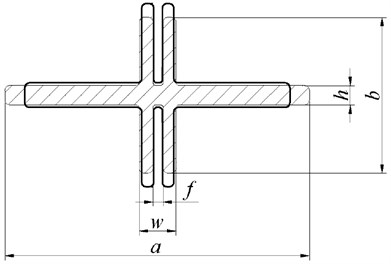
The solid line in Fig. 9 was the initial design section of part III, and the dashed line was the optimized section. According to the sectional view, the section width a after optimization was reduced, while the section height b was increased. The area of the section changes not so much. Sizes of the section for the flexible beam before and after optimization were shown in Table 2.
Table 2Sizes of section for the flexible beam before and after optimization
Sizes of part III | Initial value (mm) | Optimized value (mm) |
a | 99.11 | 86.36 |
b | 49.99 | 62.23 |
w | 15.08 | 12.38 |
h | 8.01 | 8.97 |
f | 4.96 | 4.10 |
A rotor blade model was built based on the optimized scheme to analyze the changes of the modal frequency and modal shape as well as the vibration loads.
4.3.1. Changes of modal frequency and modal shape before and after optimization
The changes of the blade vibration loads would be caused by the changes of the modal frequency and modal shape of the rotor blades. The reduction vibration effect of the multi-objective optimization design was shown in the changes of modal frequency and modal shape. See Table 3 for the changes of each order frequencies before and after optimization.
Table 3Changes of the frequencies for the blades before and after optimization
Modal frequency | Original data | Optimized data |
First order lead-lag | 0.6418 | 0.6171 |
First order flapping | 1.0870 | 1.0882 |
Second order lead-lag | 3.5956 | 3.4867 |
Second order flapping | 2.5685 | 2.5724 |
According to Table 3, the changes of the frequencies after optimization were deviated from frequency ratio 3, 4 and 5. Therefore, resonance of the blades was avoided. See Fig. 10 to Fig. 13 for the changes of each order modal shape before and after optimization.
Change curve of the vibration modal shapes before and after optimization were shown in Fig. 10 to Fig. 13. The figures showed that the magnitudes of the curves for the initial vibration modal shapes were reduced after optimization. The optimization scheme was feasible.
Fig. 10The changes of the first order flapping modal shape
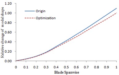
Fig. 11The changes of the first order lead-lag modal shape
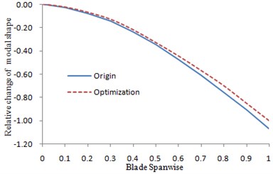
Fig. 12The changes of the second order flapping modal shape
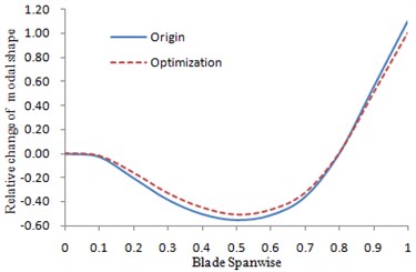
Fig. 13The changes of the second order lead-lag modal shape
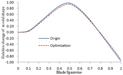
4.3.2. Changes of the vibration loads before and after optimization
The multi-objective optimization was carried out on the rotor hub system with the vibration loads as the emphasis. The changes of the loads were shown in Fig. 14.
Fig. 14The changes of the vibration loads before and after optimization
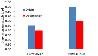
It could be seen from Fig. 14 that the lateral loads and vertical load have been reduced obviously after optimization. Moreover, the reduction degree of the vertical load was larger than the lateral one, which was more beneficial for reducing the vibration displacement during the work process of the rotor hub through the mentioned experimental comments.
5. Conclusions
The flapping and lead-lag characteristics of the rotor hub were tested experimentally in the paper. It was shown in results that a big vibration displacement was generated from the rotor hub under two working conditions. However, a larger vibration displacement was generated from the flapping than that of the lead-lag. Therefore, it is necessary to conduct optimization design to the rotor hub. Analysis was carried out to aero-elastic dynamics of bearing-less rotor. Afterwards, a multi-objective optimization model for reducing vibration and aero-elastic dynamic of bearing-less rotor was built. Pareto front of multi-objective optimization design for bearing-less rotor was acquired by Genetic Algorithm (GA). To reduce the optimization burdens, the aero-elastic dynamic model was replaced by Radial Basis Function (RBF) model during the optimization. To decrease the computational costs, the sample points with the minimum point set center deviation of the current surrogate model were added gradually. Meanwhile, the design schemes of Pareto front were ranked by TOPSIS to select the design scheme with the maximum satisfaction. Comparison was carried out between the rotor design scheme with the maximum satisfaction and the unoptimized model in terms of modal frequency, modal shape and vibration load of the hub. The results showed that the dynamic performance of the optimized rotor was improved significantly. The method in this paper also provided a important reference for multi-objective optimization of aero-elastic dynamic and engineering design of other rotors.
References
-
Hansford R. E., Vorwald J. Dynamics workshop on rotor vibratory loads prediction. Journal of the American Helicopter Society, Vol. 43, Issue 1, 1998, p. 76-87.
-
Padfield G., White M. Measuring simulation fidelity through an adaptive pilot model. Aerospace Science and Technology, Vol. 9, Issue 5, 2005, p. 400-408.
-
Gennaretti M., Bernardini G. Aeroacousto-elastic modeling for response analysis of helicopter rotors. Variational Analysis and Aerospace Engineering: Mathematical Challenges for Aerospace Design, Springer Optimization and Its Applications, Vol. 66, 2012, p. 27-50.
-
Yuan K. A., Friedmann P. P. Structural optimization for vibratory loads reduction of composite helicopter rotor blades with advanced geometry tips. Journal of the American Helicopter Society, Vol. 43, Issue 3, 1998, p. 246-256.
-
Stojković M., Soumis F. An optimization model for the simultaneous operational flight and pilot scheduling problem. Management Science, Vol. 47, Issue 9, 2001, p. 1290-1305.
-
Patil B. V., Bhartiya S., Nataraj P. S. V., et al. Multiple-model based predictive control of nonlinear hybrid systems based on global optimization using the Bernstein polynomial approach. Journal of Process Control, Vol. 22, Issue 2, 2012, p. 423-435.
-
Calvete H. I., Galé C., Oliveros M. J. Bilevel model for production–distribution planning solved by using ant colony optimization. Computers and Operations Research, Vol. 38, Issue 1, 2011, p. 320-327.
-
Ganguli R. Optimum design of a helicopter rotor for low vibration using aeroelastic analysis and response surface methods. Journal of Sound and Vibration, Vol. 258, Issue 2, 2002, p. 327-344.
-
Papila N., Shyy W., Griffin L., et al. Shape optimization of supersonic turbines using global approximation methods. Journal of Propulsion and Power, Vol. 18, Issue 3, 2002, p. 509-518.
-
Liu G. Q. The Shape Design of the Rotor Blade for Helicopter Based on Genetic Algorithm. Nanjing University of Aeronautics and Astronautics, Nanjing, 2011.
-
Crossley W. A., Laananen D. H. The genetic algorithm as an automated methodology for helicopter conceptual design. Journal of Engineering Design, Vol. 8, Issue 3, 1997, p. 231-250.
-
Huang C. M., Hsieh C. T., Wang Y. S. Evolution of radial basic function neural network for fast restoration of distribution systems with load variations. International Journal of Electrical Power & Energy Systems, Vol. 33, Issue 4, 2011, p. 961-968.
-
Beatson R. K., Levesley J., Mouat C. T. Better bases for radial basis function interpolation problems. Journal of Computational and Applied Mathematics, Vol. 236, Issue 4, 2011, p. 434-446.
-
Hickernell F. A generalized discrepancy and quadrature error bound. Mathematics of Computation of the American Mathematical Society, Vol. 67, Issue 221, 1998, p. 299-322.
-
Dashti Z., Pedram M. M., Shanbehzadeh J. A multi-criteria decision making based method for ranking sequential patterns. International MultiConference of Engineers and Computers Scientists, 2010, p. 17-19.
-
Zhang Wang-shou, et al. Assessment and zoning of non-point source pollution by multi-criteria analysis: a case study in the watershed of Beizhai. Acta Scientiae Circumstantiae, Vol. 33, Issue 1, 2013, p. 258-266.
-
Zhou Wei, et al. Evaluation of service capacity of urban CHCs in 11 cities in Jiangxi province. Chinese General Practice, Vol. 16, Issue 1, 2013, p. 26-28.
-
Mu Xiong-fei, et al. The study of site selection of distribution centrebases on TOPSIS. Modern Economics, 2012, p. 25-29.
About this article
The support of National Natural Science Foundation of China (11102184) are gratefully acknowledged.
