Abstract
Based on the governing equations of energy flow analysis in plate and acoustic domain, an unstructured zero-order energy finite element method (uEFEM0) formulation is presented to simulate the high-frequency behavior of plate structures in contact with acoustic cavities. The new formulation is derived using EFEM0, in which the energy primary variable is conserved in each element. The bending, longitudinal, and shear wave fields in the plates are all included. By meshing plates with triangular grids and cavities with tetrahedral grids, this new formulation can be easily used for modeling structures with arbitrary shape. The formulation is validated by comparing the results obtained from uEFEM0 with those from statistical energy analysis and literature. Good correlations are observed, and the advantages of the uEFEM0 formulation are identified.
1. Introduction
Vibration analysis in high-frequency range is an important part in the design phase to reduce the vibration level of the structures. The finite element method (FEM) and boundary element method (BEM) are rational choices to predict the vibration level of structures in low-frequency range. However, the wavelength is relatively short and the data, such as material properties and joint behavior, are highly uncertain for high-frequency problems [1]. Thus, a large number of elements are demanded, and FEM and BEM at high frequency require unreasonable computation time and storage, and the analysis result would be highly uncertain.
Averaging is considered a feasible way to overcome the frequency limitations of traditional deterministic methods. Statistical energy analysis (SEA), developed by Lyon [2], is widely accepted as an analysis tool in practice because of its easy-to-understand nature. In SEA, a built-up structure is divided into a number of subsystems, and a single-averaged lumped energy with respect to time and space in each subsystem is provided at the end. Therefore, SEA possesses difficulties in determining the spatial variation of energy density of the domain of interest.
This disadvantage is overcome by introducing energy flow analysis (EFA), which is based on a differential equation of energy density [1, 3-8]. EFA is an effective method for predicting distribution of the time- and space- averaged energy density and the power flow path. It is based on a set of assumptions [9], enumerated as follows: (1) linear, elastic, dissipative and isotropic systems; (2) small hysteretic damping loss factor (η≪1); (3) steady-state conditions with harmonic excitation of frequency ω; (4) far from singularities, evanescent waves are neglected; and (5) interferences between propagative waves are not considered. In 1989, Nefske and Sung [6] applied EFA on high-frequency vibration in beam-like structure and developed the energy finite element method (EFEM). This approach was extended within other basic types of structures, such as rod [1], plate [4, 10] and acoustic domain [8]. Zhang et al. [11] presented an alternate approach, and derived the EFEM governing equations for plate or an acoustic space, in which unify governing equation is obtained. Kong et al. [12] pointed out that the high-frequency vibration in structures can be recognized as a linear superposition of the direct field and the reverberant field, and the results obtained from EFA is the reverberant field part. Several researchers tried to modify the governing equations in specific structures, in order to extent the validity region of EFA [13-16]. In 2011, a random EFA was proposed by You et al. [17], which can be employed to predict the high-frequency vibration level of structures under a random loading.
When applying EFEM in complex structures, a problem is that the energy density is discontinuous at the junctions [6], so that the elements at the junctions must be physically disconnected by duplicate nodes at the joints. In 2000, Wang [5] used a piece-wise constant approximation to the energy differential equations and developed a zero-order EFEM (EFEM0), in which the variables are stored in the centroid of the control volumes so that duplicate nodes are not necessary. Thus, the existing FEM mesh can be more easily used to perform an EFEM0 analysis. However, in his research, the EFEM0 is based on structured grids, and only beam and plate structures are considered, the vibration motion of acoustic domain is not included.
In this paper, a new formulation of unstructured EFEM0 (uEFEM0) that considers both out-plane and in-plane waves is presented, in which plates and acoustic domains are meshed by triangular and tetrahedral grids, respectively. By applying the analytical method to evaluate the power transfer coefficients between structural-structural [18] and structural-acoustic [8] junctions, this new formulation can be employed to solve high-frequency structural-acoustic problems of built-up structures with arbitrary shape. Two numerical examples are given to verify the new formulation.
2. Overview of FEA
The procedures of the EFA are initially reviewed to develop the uEFEM0 formulation including a brief review on the power transfer through the joints.
2.1. Energy flow equation
The EFA governing differential equation for steady state problem can be developed by considering orthogonal and incoherent waves traveling within the wave-bearing domain of interest and expressed as [11]:
where e is the time- and space-averaged energy density, which characterizes the vibration behavior. ω is the circular frequency of the analysis, cg is the group speed, η is the hysteresis damping factor, and πin is the injected power density. The first term on the left side of Eq. (1) represents the transmitted power, and the second term represents the dissipated power. Thus, Eq. (1) expresses an energy flow balance that involves the power flow, energy loss, and injected power density.
Table 1Form in different vibrating systems
Configuration | Energy equation | Group velocity |
Bending wave | -c2g(∂2e∂x2+∂2e∂y2)+ηωe=πin | cg=2ω4√ρshω2/D |
Longitudinal wave | -c2g(∂2e∂x2+∂2e∂y2)+ηωe=πin | cg=√E/ρs(1-ν2) |
Shear wave | -c2g(∂2e∂x2+∂2e∂y2)+ηωe=πin | cg=√E/2ρs(1+ν) |
Acoustic wave | -c2g(∂2e∂x2+∂2e∂y2+∂2e∂z2)+ηωe=πin | cg=c0 |
In typical vibrating systems, the form of Eq. (1) is slightly different. As enumerated in Table 1, ρs is the structural density, E and ν are the Young’s modulus and Poisson ratio, respectively, D is the flexural rigidity, and c0 is the sound speed. Notably, the energy densities in plates and acoustic domains are recognized as surface and bulk densities, respectively.
2.2. Power flow on coupling boundary
Notably, the governing equations enumerated in Table 1 are valid if the structure and the fluid (air) do not affect each other. However, the primary variable e is discontinuous at the boundaries of connecting elements at the junctions for a structural–acoustic coupled system. These discontinuities can originate from the geometry, from multiple components connected together, from the change of material, or from the different medium interface [7], where ever a reflection/refraction of traveling wave occurs. The structural bending, longitudinal, shear motion, and acoustic motion will not affect each other unless structural-structural or structural-acoustic interfaces exist [19].
In this work, two kinds of discontinuities are considered, namely, Plate-Plate (P-P) joint, which represents a junction of plates, and Plate-Acoustic (P-A) joint, which represents an interface of plate and acoustic domain. As deduced by Dong et al. [19], the relationship between the power flow through the discontinuities and the energy density on the boundary of the discontinuities has the same form in both P-P and P-A joints, as:
where I is an identity matrix, cg is a diagonal matrix formed by the group speeds of coupling waves, and τ is the power transfer coefficient matrix. The dimensions of the matrices are 2×2 for P-A joints, and 3n×3n for P-P joints, where n is the number of plates which constitute the joint. In this formulation, all the three wave types in plates are considered.
2.3. P-A joint relationship
For a structural-acoustic coupling problem, the bending vibration induces the acoustic wave, and the acoustic wave also affects the bending vibration. Zhang et al. [20] pointed out that because of the effect of fluid loading on the structure, the governing equation of bending wave in Table 1 should be modified as follows:
where ηrad is the radiation damping, which is defined as:
In Eq. (4), the parameter α can be calculated by:
where fc is the coincidence frequency, at which the structural bending wave number kb equals to the acoustic wave number k. The bending group speed should be computed with the formulation cgB=2(Dω2/αρsh)1/4, where D is the flexural rigidity of the plate.
The radiation efficiency σrad quantifies the interaction between structure bending and acoustic waves, the formulation proposed by Leppington [21] is used in this work:
where r=a/b(r≥1) is the ratio between the characteristic length a and b of the plate, μ=ksB/k is the wave number ratio, and λc=c0/fc is the wavelength of acoustic wave at the coincidence frequency fc.
By the physical meaning of σrad, Bitsie [8] derived the power transfer coefficients between bending wave in plate and acoustic wave in air, as:
As the result of conservation law, τbb=1-τba and τaa=1-τab.
Considering the P-A joint, the form of the matrices in Eq. (2) can be written as:
2.4. Power flow through the P-P joint
Langley and Heron [18] discussed how to compute the power transfer coefficients between an arbitrary number of plates connected to a common beam, using a wave dynamic stiffness matrix method. In this method, the complete set of transmission coefficients is written in the form of τijpr, where respectively i and p represent the carrier plate and waveform of the incident wave, and j and r represent those of the generated wave. If i=j, τ is recognized as a reflection coefficient. Their published paper has several errors, which are enumerated in Appendix.
If considering a P-P joint, which consists of two plates denoted by i and j, the matrices in Eq. (2) are in the form of:
3. Implementation of uEFEM0
The discretization procedure of governing equations in Table 1 is realized by EFEM0 with unstructured mesh, which indicates that the triangular grids are used for the three types of waves in 2D plates and the tetrahedral grids are used for the acoustic waves in 3D acoustic domains. When the grids are produced, each grid is recognized as a control volume, and the variables are cell-centered, which indicates that they are stored at the centroids of each control volume.
Notice that the governing equation, Eq. (1), is analogous to heat conduction equation, which can be integrated in an elemental control volume Vi, as:
A simple piece-wise constant approximation in Vi is applied for the latter two terms, expressed as:
and by applying the divergence theorem, the first term can be transferred into the power flux through the common boundary of adjacent cells, as:
where Qi,j represents the power flux from Vi to its jth adjacent volume Vj, and m is the number of common boundaries. In this paper, different treatments [22, 23] are carried out to calculate Qi,j in 2D and 3D domains.
3.1. Calculation of Qi,j in 2D domain
Fig. 1(a) shows the schematic of two adjacent control volumes of the unstructured grids in a plate, whose centroids are denoted as Zi and Zj, respectively, and their common boundary is -AB. In Fig. 1(b), ti,j and ni,j are the tangential and normal unit vectors of -AB, respectively, and τi,j and νi,j are the unit vectors of the one starting at Zi pointing to Zj and its vertical one, respectively. θ is the angle between τi,j and ti,j. di and dj are the distances from each centroid of Zi and Zj to -AB , respectively. M is the intersection of -AB and ¯ZiZj.
Fig. 1Two adjacent control volumes and vectors definition on the common boundary in 2D domain
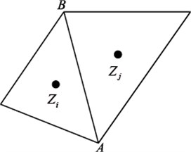
a) Volumes Zi and Zj
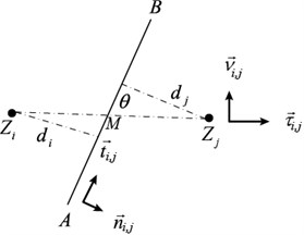
b) Vectors definition on -AB
In 2D plates, the net power flow density qi,j is assumed to be uniform on the common boundary ¯AB; thus, the power flux Qi,j can be easily expressed as:
where Lj is the length of ¯AB, and h is the thickness of the plate. In this work, the triangular grid is used for the plates; thus, the number of adjacent control volume for each grid, m in Eq. (12), is equal to 3, and qi,j is in the form of:
Note that the vectors τi,j and ti,j are non-collinear, so ni,j can be decomposed into ni,j=aτi,j+bti,j, where:
then the power flux density is resolved into these two directions, and a finite difference is used in each direction for numerical approximation, as in Vi one can obtain:
and similarly in Vj, the opposite net flow density is:
The symbol |¯P1P2| indicates the distance of the two involved points, P1 and P2.
The power flux through the common boundary ¯AB is continuous, which yields:
Substituting Eqs. (16), (17) to Eq. (18), eM can be easily solved as:
then substituting Eq. (19) into Eq. (16), and notice that:
One can eliminate uM and the approximation formula of qi,j can be written as:
From Eqs. (13) and (21), the power flux through one boundary of the element Zi is solved. This procedure is repeated m times and is superposed. Then, the superposition of all the power flux out of the element Zi can be worked out, which indicates that the first term of Eq. (10) is finally solved.
3.2. Calculation of Qi,j in 3D domain
As shown in Fig. 2, Zi and Zj denote the centroids of two adjacent tetrahedral grids in 3D domain, whose common boundary is a triangle denoted by ∆, and is the centroid of .
First, two functions should be introduced:
represents the volume of a tetrahedron whose vertices are , , and . An area vector, , is in the form of:
The use of commas emphasizes that the subscripts , and in Eq. (23) are directive, which is different from those in Eq. (22). The direction of vector is determined by right hand rule, starting from to and then to .
The governing equation of acoustic domains has the same form as that of plates (listed in Table 1), but the power flow flux from to , , is divided into three parts in 3D solution:
The gradient, in each part, for example, is averaged in a secondary tetrahedron, :
Otherwise, a similar approximation in while calculating will lead to:
To guarantee the conservativeness of the power flux through the common boundary :
Substituting Eqs. (25), (26) into Eq. (27), can be eliminated, and results in:
where the scalar coefficients can be solved as:
and:
Similar to Eq. (28), the other two parts of power flux, and , can be worked out. Once they are all determined, submit them into Eq. (24), then in 3D domain can be obtained.
Fig. 2Two adjacent control volumes in 3D domain
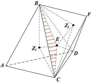
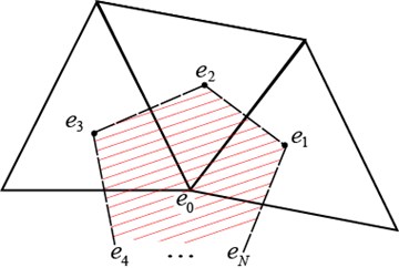
Fig. 3Interpolation diagram for computing vertex weighted average e0 from surrounding cell-centered ei
3.3. Node interpolation
When calculating in both 2D and 3D domains, the variable at the vertex, , is unknown, as shown in Fig. 3; it is evaluated by a weighted average of the surrounding cell-centered values, ∼, as [24]:
in which the weight functions are selected to ensure zero Laplacian of the linear function in the shadow region (Fig. 3). is the number of the surrounding cells.
Aiming at this, Lagrangian multipliers, , and , are employed, and the weight function is expressed as:
where are the spatial locations of the centroids of the cells, and is that of the vertex. The Lagrangian multipliers are computed by the local geometric parameters as:
where:
The interpolation coefficients are computed as:
3.4. Assembling the global equation
First, is initially computed for each common boundary in 2D and 3D domains, and if the boundary is on any joint, is computed using Eq. (2) instead. Then, the results are summarized into Eq. (10) and all the element stiffness equations are worked out. Lastly, the corresponding coefficients of each control volume are gathered, and the global equation can be written in a general form as:
where , and are the numbers of control volumes in plates and air cavities, respectively. The notations , , , and , represent the bending, longitudinal, shear, and acoustic waves, respectively. The diagonal matrices BB, LL, and so on, are assembled from of each wave domain, and the other matrices are from the power transfer of the junctions. is the energy density vector, and is the vector of corresponding power injected into every element.
4. Validation
In this section, two numerical examples are developed to confirm the validity of the proposed uEFEM0. The accuracy of the result obtained from uEFEM0 is verified by establishing corresponding models by AutoSEA [25], a commercial software of SEA. The result obtained from uEFEM0 is the distribution of energy densities and that of SEA is the lumped energy of each subsystem. For comparison, the results of uEFEM0 are integrated into the lumped energy of each subsystem defined by the SEA model as:
4.1. Seven-plate engine foundation model
Several researchers have investigated the 1:2.5 scale model of the diesel propulsion engine foundation and the hull structure of a frigate ship to study the solution of high-frequency structural vibration based on energy flow approach. Lyon [26] divided this model into 7 and 12 substructures and studied the significance of the in-plane energy in energy transmission by the SEA method. Vlahopoulos et al. [3] applied EFEM on this seven-plate structure and obtained consistent results with those of Lyon.
Fig. 4Seven-plate engine foundation model
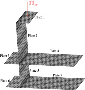
In this paper, the material properties and the dimensions of plates of the seven-plate model are the same as those in Ref. [3]. The uEFEM0 model comprises 660 nodes, 1170 triangular control volumes, and 27 P-P joints, as shown in Fig. 4.
The analysis is carried out in thirteen 1/3 octaves that cover from 1.25 kHz to 20 kHz, as listed in Table 2. In each octave band, a unit bending power of 1 W is injected at the center of plate 1, whereas it is applied on the top plate in the corresponding SEA model. On all the boundaries of the system, the boundary condition is set as .
Table 2Computing frequency range, thirteen 1/3 octaves
Octave ID. | 1 | 2 | 3 | 4 | 5 | 6 | 7 | 8 | 9 | 10 | 11 | 12 | 13 | |
Frequency (kHz) | Center | 1.25 | 1.6 | 2 | 2.5 | 3.15 | 4 | 5 | 6.3 | 8 | 10 | 12.5 | 16 | 20 |
Lower limit | 1.12 | 1.41 | 1.78 | 2.24 | 2.82 | 3.55 | 4.47 | 5.62 | 7.08 | 8.91 | 11.2 | 14.1 | 17.8 | |
Upper limit | 1.41 | 1.78 | 2.24 | 2.82 | 3.55 | 4.47 | 5.62 | 7.08 | 8.91 | 11.2 | 14.1 | 17.8 | 22.4 | |
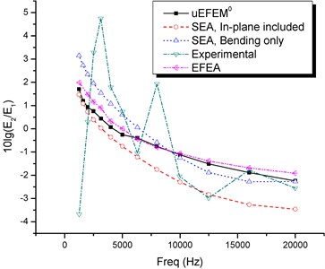
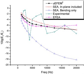
Fig. 5 shows the comparison of the total bending energy of plates 1, 4, and 7. The bending energy ratios between plates 7 to 1 and plates 2 to 1 are presented in Figs. 7(a) and 7(b), the results with the legend of ‘EFEA’ were developed by Vlahopoulos [3], and the experimental results were provided by Lyon [26].
It can be demonstrated that:
1) The bending energy results of the incident plate (Plate 1) fit well, whereas those of other plates have slight difference, which is less than 3 dB. This finding is attributed to the plates except the incident plate; the energy is induced by the joints, and different treatments are applied with the joints in uEFEM0 and SEA.
2) As observed in Figs. 7(a) and 7(b), the developed uEFEM0 shows the best overall correlation to the experimental data.
3) When only the bending mechanism is included in the formulation, power can be transferred from plates 1 to plate 7 only from the bending motion, while in fact an important amount of power is transferred from the in-plane motion of plates 2 and 5. Thus, the SEA result with only bending wave included shows a significant error on the energy ratio between plate 7 to plate 1.
4) The uEFEM0 formulation is based on a FEM mesh of the structure. Therefore, the spatial distribution of the energy density can be identified easily (Fig. 6).
Fig. 5Bending energy results in plates 1, 4 and 7 (results from uEFEM0, SEA/AutoSEA)
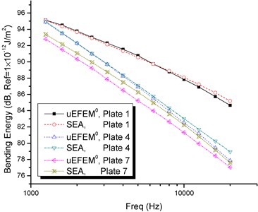
Fig. 6Distribution of bending energy density on the seven-plate model at 1.25 kHz (result from uEFEM0, and the unit: dB, ref = 1×10-12 J/m2)
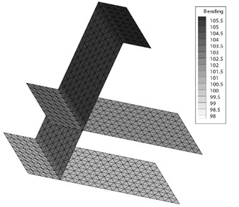
Fig. 7Bending energy ratio between plates (results from uEFEM0, SEA/AutoSEA, and literature)
a) Plates 2 to 1
b) Plates 7 to 1
4.2. Simplified passenger vehicle model
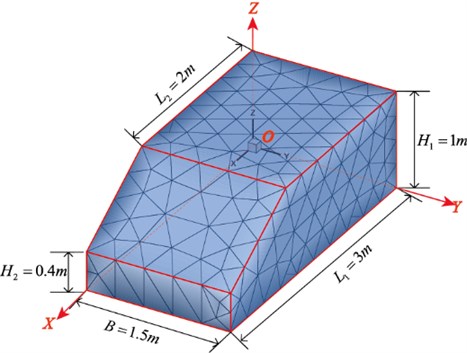
A passenger vehicle is simplified to seven structural plates with an internal air cavity. The plates are made of aluminum, with a uniform thickness 5 mm, and the internal cavity is filled with air. The dimensions and mesh of the vehicle are both shown in Fig. 8. The model comprises 468 structural plate elements and 1220 acoustic air elements, with 79 P-P joints and 468 P-A joints. The injected powers, 0.25 W each in any octave, are applied at about the positions of four wheels, which are (0.6, 0.3), (0.6, 1.2), (2.5, 0.3), and (2.5, 1.2) in the coordinate system set on the base plate. In the SEA model, a unit power of 1 W is applied at the base plate. The side plates are examples of plates with irregular shape, which would be difficult to deal with EFEM0 developed by Wang [5], but easy with this presented uEFEM0.
The material properties are listed in Table 3, and the analysis frequency range is the same as the prior numerical example, which is listed in Table 2.
Table 3Material properties of the vehicle model
Aluminum (plates) | Air (cavity) | |||||
Elastic modulus (GPa) | Density (kg/m3) | Poisson ratio | DLF* | Density (kg/m3) | Sound speed (m/s2) | DLF* |
70 | 2700 | 0.33 | 0.06 | 1.23 | 340 | 0.005 |
*DLF: Damping loss factor. The DLFs of all the three wave domains in plates are set the same as . | ||||||
Fig. 8uEFEM0 model of simplified vehicle
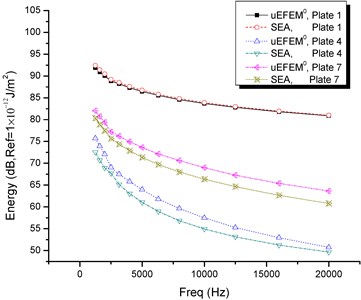
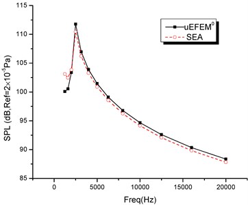
Figs. 9(a) and 9(b) show the comparison of results from uEFEM0 and AutoSEA, including the bending energy of plates and sound pressure level (SPL) of the cavity. The spatial variation of the energy density is presented in Fig. 10. From the analysis of the simplified vehicle, the following conclusions can be summarized:
1) Similar to the behaviors of uEFEM0 and SEA analysis in the prior numerical example, the total bending energy of the incident plate shows a good agreement, whereas the results in other plates are slightly deviated. The result of SPL fits well for these two methods.
2) As observed in Fig. 10, the bending energy level is highest at the loading points and decreases as the distance of the loading points increases. The in-plane energy takes its peak in the side plates, which have the same direction with the loading forces. This phenomenon explains the importance of the in-plane energy in the energy transmission in such structures including ‘L’ angles. The SPL shows a significant value at the corners between the base and side plates. This result is due to a number of plate elements with relatively high bending energy that radiate energy into the air cavity at those corners.
3) The simplified passenger vehicle application demonstrates how the uEFEM0 formulation can be utilized as a simulation tool for structural-acoustic car applications, thus it may potentially be further developed to be an NVH tool.
Fig. 9Comparison of bending energy in several plates and sound pressure level in air cavity
a) Bending energy
b) Sound pressure level
5. Conclusions
An unstructured zero-order EFEM formulation is developed for structural–acoustic problem, and both bending and in-plane waves are considered in the plate structure. The derived formulation is applied to predict the energy distributions of a seven-plate structure and a simplified vehicle model with an internal air cavity. The formulation is validated by comparing the results obtained from conventional simulation methods and experiments. The bending wave energy decreases as the distance of the location increases from the exciting point. The in-plane wave energy has significant values in the plates, which have the same direction with that of the input power, and the highest SPL most likely exists at the corners. Omitting the in-plane wave motion results in a significant underestimation in the structures far from the loading points.
Compared with SEA, the developed uEFEM0 formulation takes the advantage in determining the energy distribution. Moreover, uEFEM0 guarantees the conservativeness of energy in any elemental control volume and addresses the difficulty of traditional EFEM0 in dealing with irregular shapes. This work is the first to solve a structural-acoustic problem using a zero-order EFEM.
Fig. 10Cloud charts of energy density and sound pressure level, at f= 6.3 kHz (The unit of energy density is dB, ref = 1×10-12 J/m2, and that of SPL is dB, ref = 2×10⁻⁵ Pa)
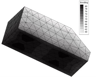
a) Bending energy density
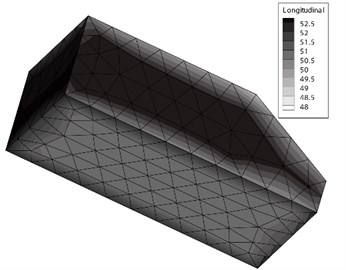
b) Longitudinal energy density
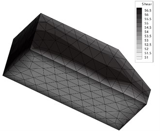
c) Shear energy density
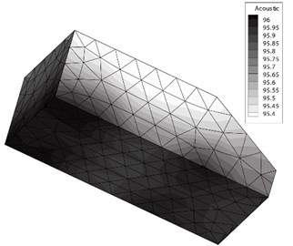
d) Sound pressure level
References
-
Wohlever J. C., Bernhard R. J. Mechanical energy-flow models of rods and beams. Journal of Sound and Vibration, Vol. 153, Issue 1, 1992, p. 1-19.
-
Lyon R. Statistical Energy Analysis of Dynamical Systems: Theory and Applications. MIT Press Cambridge, MA, 1993.
-
Vlahopoulos N., Garza-Rios L. O., Mollo C. Numerical implementation, validation, and marine applications of an energy finite element formulation. Journal of Ship Research, Vol. 43, Issue 3, 1999, p. 143-156.
-
Bouthier O. M., Bernhard R. J. Models of space averaged energetics of plates. AIAA-1990-3921, 1990.
-
Wang S. High Frequency Energy Flow Analysis Methods: Numerical Implementtation, Applications, and Verification. Ph.D. Thesis, Purdue University, 2000.
-
Nefske D., Sung S. Power flow finite element analysis of dynamic systems: basic theory and application to beams. Journal of Vibration Acoustics Stress and Reliability in Design, Vol. 111, Issue 1, 1989, p. 94-100.
-
Vlahopoulos N., Wu K., Medyanik S. Energy finite element analysis for structural-acoustic design of naval vehicles. Journal of Ship Production and Design, Vol. 28, Issue 1, 2012, p. 42-48.
-
Bitsie F. The Structural-Acoustic Energy Finite-Element Method and Energy Boundary-Element Method. Ph.D. Thesis, Purdue University, 1996.
-
Ichchou M. N., Jezequel L. Letter to the editor: comments on simple models of the energy flow in vibrating membranes and on simple models of the energetics of transversely vibrating plates. Journal of Sound and Vibration, Vol. 195, Issue 4, 1996, p. 679-685.
-
Park D. H., Hong S. Y., Kil H. G., Jeon J. J. Power flow models and analysis of in-plane waves in finite coupled thin plates. Journal of Sound and Vibration, Vol. 244, Issue 4, 2001, p. 651-668.
-
Zhang W. G., Wang A. M., Vlahopoulos N. An alternative energy finite element formulation based on incoherent orthogonal waves and its validation for marine structures. Finite Elements in Analysis and Design, Vol. 38, Issue 12, 2002, p. 1095-1113.
-
Kong X., Chen H., Zhu D., Zhang W. Study on the validity region of energy finite element analysis. Journal of Sound and Vibration, Vol. 333, Issue 9, 2014, p. 2601-2616.
-
Han J. B., Hong S. Y., Song J. H., Kwon H. W. Vibrational energy flow models for the 1-d high damping system. Journal of Mechanical Science and Technology, Vol. 27, Issue 9, 2013, p. 2659-2671.
-
Kwon H. W., Hong S. Y., Park D. H., Kil H. G., Song J. H. Vibrational energy flow models for out-of-plane waves in finite thin shell. Journal of Mechanical Science and Technology, Vol. 26, Issue 3, 2012, p. 689-701.
-
Xie M., Chen H., Wu J. Energy finite element analysis to high-frequency bending vibration in cylindrical shell. Journal of Xi’an Jiaotong University, Vol. 42, Issue 9, 2008, p. 1113-1116.
-
Xie M., Chen H., Wu J. H. Transient energy density distribution of a rod under high-frequency excitation. Journal of Sound and Vibration, Vol. 330, Issue 12, 2011, p. 2701-2706.
-
You J., Meng G., Li H. Random energy flow analysis of coupled beam structures and its correlation with sea. Archive of Applied Mechanics, Vol. 81, Issue 1, 2011, p. 37-50.
-
Langley R., Heron K. Elastic wave transmission through plate/beam junctions. Journal of Sound and Vibration, Vol. 143, Issue 2, 1990, p. 241-253.
-
Dong J., Choi K., Wang A., Zhang W., Vlahopoulos N. Parametric design sensitivity analysis of high-frequency structural-acoustic problems using energy finite element method. International Journal for Numerical Methods in Engineering, Vol. 62, Issue 1, 2005, p. 83-121.
-
Zhang W., Wang A., Vlahopoulos N., Wu K. High-frequency vibration analysis of thin elastic plates under heavy fluid loading by an energy finite element formulation. Journal of Sound and Vibration, Vol. 263, Issue 1, 2003, p. 21-46.
-
Leppington F., Broadbent E., Heron K. The acoustic radiation efficiency of rectangular panels. Proceedings of the Royal Society of London. A. Mathematical and Physical Sciences, Vol. 382, Issue 1783, 1982, p. 245-271.
-
Liu X. Z., Yu Y. L., Wang R. L., Lin Z. A cell-centered finite volume scheme for discretizing diffusion equation on unstructured arbitrary polygonal meshes. Journal on Numerical Methods and Computer Applications, Vol. 31, Issue 4, 2010, p. 259-270.
-
Yin D. S., Du Z. P., Lu J. P. An unstructured tetrahedral mesh finite volume difference method for the diffusion equation. Journal on Numerical Methods and Computer Applications, Vol. 26, Issue 2, 2005, p. 92-100.
-
Athavale M. M., Jiang Y., Przekwas A. J. Application of an unstructured grid solution methodology to turbo machinery flows. AIAA-95-0174, 1995.
-
Clifton S. M. AutoSEA User Guide. 1993.
-
Lyon R. H. In-plane contribution to structural noise transmission. Noise Control Engineering Journal, Vol. 26, Issue 1, 1986, p. 22-27.
-
Kim N. H., Dong J., Choi K. K. Energy flow analysis and design sensitivity of structural problems at high frequencies. Journal of Sound and Vibration, Vol. 269, Issue 1, 2004, p. 213-250.
