Abstract
The electromechanical integrated magnetic gear (EIMG) is a new type of the magnetic gears, in which the traditional field modulated magnetic gear, drive and control are integrated. Considering the torque wave, the dynamic model of the EIMG system with four subsystems was founded and the resonance responses were discussed. The results show that the strong resonances will occur when the excited frequency is close to the natural frequencies of the inner rotor, the outer ferromagnetic pole-piece and the outer stator torsional modes. The resonances hardly happen when the excited frequency is close to other natural frequencies.
1. Introduction
Magnetic gear is a kind of the magnetic transmission and has many advantages, such as non-contact, non-wear, lower vibration and noises, and so on. They overcome the mechanical fatigues and other disadvantages of the mechanical gears, and have some significant advantages, such as, reduced maintenance, improved reliability, no lubrication, overload protection, and so on [1]. Field modulated magnetic gear (FMMG) proposed by K.Atallah adopts the coaxial topology [2]. Compared with the traditional magnetic gears with the parallel shaft topology, FMMG has the higher utilization of the permanent magnets (PMs), the bigger output torque and the bigger torque density. So FMMG can be widely used in the medicine, chemical, vehicle, aerospace and other fields.
FMMG has attracted the attentions of many scholars because of the many advantages. The transmission mechanism [5], torque characteristics [6], structural optimization [7], transmission efficiency [8], rotor eccentricity [9] and so on have been studied widely. Lots of study results have been achieved. While, FMMG must be drived by the high performance motor. This make the FMMG system take up more room and the FMMG system is easy to be affected by the performance of the motor. For this reason, an electromechanical integrated magnetic gear (EIFM) was promoted by author, in which the traditional FMMG, drive and control are integrated. The EIMG system has a compact structure, the controllable torque and speed. So EIMG can be widely used in medicine, food, robot, agriculture and so on.
Because of the torque wave on the output component, the resonances always occur in the EIMG system. These will deteriorate the dynamic characteristics of the EIMG system and must be avoided. In this paper, the dynamic model of the EIMG system with four subsystems was founded. The forced responses were discussed. These can provided the theory basis for the parameter optimization.
2. Dynamic model of the EIMG system
EIMG shown in Fig. 1 is composed of the inner stator, the inner and outer ferromagnetic pole-pieces (FPs), the inner rotor and the outer stator. When the outer stator is fixed, the outer FPs will export the torque.
The undamped differential equations of the 10 DOF of the overall EIMG system can be given in matrix form as:
Fig. 1Topology and prototype of the electromechanical integrated magnetic gear
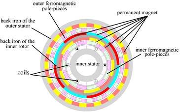
a)
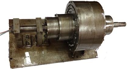
b)
The displacement vector , the mass matrix , the damping matrix and the load vector are given respectively as follows:
where , , , , , , , , , are the the equivalent masses and the masses of the inner stator, the inner FPs, the inner rotor, the outer FPs and stator, respectively; are the equivalent radius of gyration of the outer FPs. and is the wave amplitude and the excited frequency of the torque on the outer FPs. , , , , , , , , , , , are the damping coefficients among parts.
Because is a 10×10 matrix and bigger, the element in the matrix can be expressed as follows, respectively:
, , , , , , , , , , , , , , , , , , , , , , , , , , , , , , , , , , , , , , , , , , , , , , , , , , , , , , , , , , , , , , , ,
where , , , , are the transverse supporting stiffnesses of the inner FPs, the inner stator, the outer FPs, the inner rotor, the outer stator, respectively; , and are the torsional stiffnesses of the inner and outer stator, the FPs around their axes, respectively; , , and is the electromagnetic coupling stiffness among parts; , and are the relative displacement and the meshing angle among parts, respectively.
Fig. 2Dynamic model of the electromechanical integrated magnetic gear
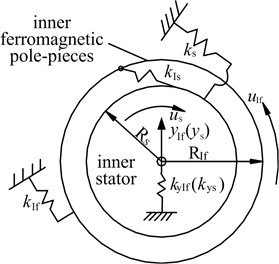
a) The inner stator/ inner FPs subsystem
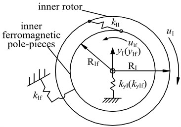
b) The inner FPs /inner rotor subsystem
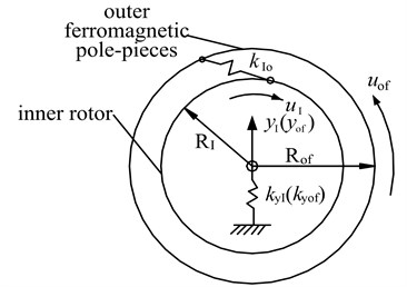
c) The inner rotor/outer FPs subsystem
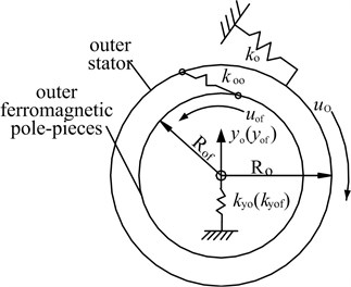
d) The outer FPs /outer rotor subsystem
The undamping differential equations of the EIMG system can be written in the matrix form as:
The natural frequencies of the EIMG system are . The normal mass matrix, the normal damping matrix, the normal force vector and the normal shape matrix are the , , and , respectively. The normal damping matrix isn’t the diagonal matrix in most cases. But the damping matrix is a diagonal matrix and the elements in the principal diagonal are much bigger than other elements. The new normal diagonal matrix can be obtained by selecting the elements in the principal diagonal. The normal differential equations of the EIMG system can be written as follows:
The general formula of the equation (3) can be expressed:
where is the damping coefficient of the -th order normal shape, .
The steady time responses of the -th order of the EIMG system can be calculated as follows:
where .
The time responses of the EIMG system in the original coordinate system can be got:
3. Forced responses of the EIMG system
The parameters of the example EIMG system are shown in Table 1. By substituting the dynamic parameters into the equation (2) to equation (6), the forced responses can be worked out and shown in Fig. 3.
Table 1Characteristic parameters of the example EIMG system
(kN/m) | (N·m) | (N·m) | (N·m) | (o) | (o) | (o) |
8.6444×10⁵ | 3.1446×10⁵ | 4.5467×10⁵ | 2.0416×10⁵ | 0.1014 | 0.1818 | 0.1435 |
(o) | (kg) | (kg) | (kg) | (kg) | (kg) | |
0.2022 | 1.3 | 1.3 | 11 | 6.2 | 7.7 | 3×10⁶ |
(N·m) | (N·m) | (N·m) | (N·m) | (N·m) | (N·m) | |
3×10⁶ | 3×10⁶ | 3×10⁶ | 3×10⁶ | 3×10⁶ | 3×10⁶ |
Fig. 3 shows that the resonance will occur when the excited frequency is close to the natural frequencies of the inner rotor torsional mode, the outer FPs and stator torsional modes. When the excited frequency is closed to the other natural frequencies, the resonances hardly happen. Meanwhile, when the resonances happen, the torsional displacements of the inner rotor, the outer FPs and stator will be bigger than the displacements of other degrees of freedom.
Because the electromagnetic coupling stiffnesses are smaller than the mechanical supporting sitffnesses, the relative displacements of the different degree of the freedom in all modes are larger different. In inner rotor torsional mode, the relative displacements of the inner FPs, the inner rotor, the outer FPs and the outer rotor are bigger. In the outer FPs torsional mode, the relative displacements of the inner rotor, the outer FPs and stator are much bigger than other degrees of the freedom. In the outer stator torsional mode, the relative displacements of the outer FPs and stator are much bigger than other degrees of the freedom. In other modes, the relative displacements are ten times different at least. So, the torsional resonance amplitudes of the inner rotor, the outer FPs and stator are much bigger than other degrees of the freedom.
Fig. 3Forced responses of the EIMG system
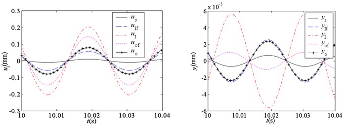
a)277 rad/s
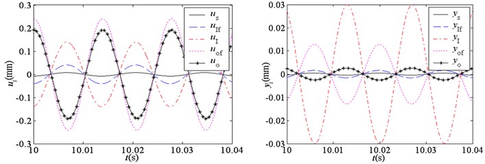
b)450 rad/s
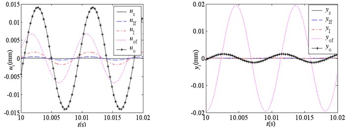
c) 694 rad/s
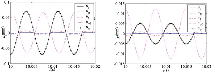
d) 830 rad/s
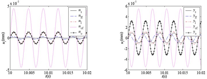
e) 1635 rad/s
4. Conclusions
Because of the torque wave on the output component, the resonances will occur when the excited frequency is closed to the natural frequencies of the inner rotor, the outer FPs and stator torsional modes. The resonances hardly happen when the excited frequency is closed to other natural frequencies. Meanwhile, the torsional displacements of the inner rotor, the outer FPs and stator are bigger and the displacements of other degrees of the freedom are smaller. The EIMG system can be widely used in the working conditions with low speed. So, the lower frequency resonances easily happen and must be avoided.
References
-
P. O. Rasmussen, T. O. Andersen, F. T. Joergense, O. Nielsen Development of a High Performance Magnetic Gear. IEEE Transactions on Industry Applications, Vol. 41, Issue 3, 2005, p. 764-770.
-
K. Atallah, D. Howe A novel high-performance magnetic gear. IEEE Transactions on Magnetics, Vol. 37, Issue 4, 2001, p. 2844-2846.
-
K. Atallah, J. Wang, D. Howe A high-performance linear magnetic gear. Journal of Applied Physics, Vol. 97, Issue 10, 2005, p. 516-516.
-
N. Niguchi, K. Hirata, Y. Hayakawa Study on transmission torque characteristics of a surface-permanent- magnet-type magnetic gear. IEEJ Transactions on Industry Applications, Vol. 131, Issue 3, 2011, p. 396-402.
-
L. N. Jian, G. Xu, J. Song, H. Xue, et al. Optimum design for improving modulating-effect of coaxial magnetic gear using response surface methodology and genetic algorithm. Progress In Electromagnetics Research, Vol. 116, 2011, p. 297-312.
-
Du Shiqin, Jiang Jianzhong, Zhang Yuejin, Gong Yu A Magnetic Gearing. Transactions of China Electrotechnical Society, Vol. 25, Issue 9, 2010, p. 41-46.
About this article
This project is supported by Natural Science Foundation of China (51205341), Research Program of Natural science at Universities of Hebei province (Q2012032), the Joint Fund of Specialized Research Fund for the Doctoral Program of Higher Education & Hebei Provincial Education Office (20121333120004).
