Abstract
The 21st century certainly poses new challenges for the construction of means and systems of transport, particularly in the greater metropolitan areas. Issues related with public transport are generally well-known. Research studies are constructively oriented towards finding solutions to reduce energy consumption, minimize construction and maintenance costs, guarantee profitability, reduce emissions of air pollutants, and first and foremost, solutions which would be human-friendly and specifically tailored to meet the needs of the people. This paper presents the concept of a new electric ECO-car designed within the remit of the scientific and research programme at Warsaw University of Technology. The car is equipped to carry both able-bodied passengers and the disabled. The car uses an integrated drive and brake-by-wire system, as well as powered by lithium-ion batteries and a super capacitor system. During the design process special attention was also paid to ergonomic issues. Due to the theme of the conference, special attention will be paid to the dynamic properties of a complex system of driver-vehicle-road. It will show dynamic phenomena in the implementation of the so-called moose test.
1. Introduction
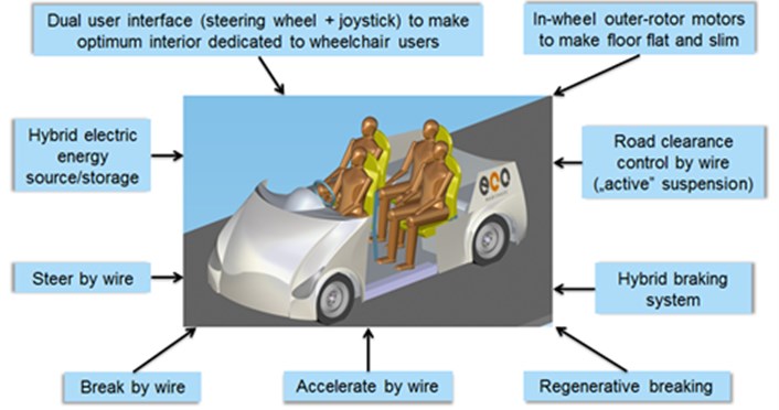
This paper presents a new concept of electric car for four passengers (both for able-bodied and disabled users). The term “adjustments for the disabled” means the vehicle allows disabled people in hand-powered wheelchairs to be able to drive the car (incl. getting into it) as well as transporting a passenger in an electric wheelchair. In the presented version of the car, the disabled are understood as those with disabilities of the lower limbs. The car has a top speed of 50 km/h and is intended for use in enclosed areas where conventional vehicle traffic is limited or forbidden. It is designed to function as part of a car rental system such as Park and Ride schemes. Therefore, such infrastructure problems such as rental and battery-charging systems, etc. must be addressed. This article focuses on selected issues related to these technical aspects. Fig. 1 illustrates some of the solutions used in the car’s design.
Fig. 1General characteristics of the presented car
Due to this paper’s limited scope, it will focus on the following issues:
– Vehicle’s computer simulation (regarding a disable driver);
– Ergonomic analysis.
Computer simulations, as mentioned previously, include an analysis of the dynamic properties of the system: the driver-car, during moose test. Thus, the system is analyzed comprehensively. The system takes into account the human factor and car dynamics.
2. ECO-car functionality and versatility
The notion of being “human-friendly and specifically tailored to meet the needs of the people” has been developed based on the assumption which radically differs from the design “philosophy” in the current means of transport. The vehicles should be “universal”, with construction allowing easy and independent handling both for fit persons and persons with disabilities, without extra-special equipment. The means of transport used today call for individual adjustments to meet the needs of persons with disabilities. The different approach is based on the fact that European societies are facing increasing rates of persons with disabilities and seniors; hence improvement of their mobility in a broad sense becomes critically important in the social and economic context. As it was mentioned a person with limited mobility will drive from the vantage position of their own wheelchair. This factor necessitated adequate space for boarding and positioning the wheelchair within the cabin. The vehicle is also equipped with a special securing system to prevent the wheelchair from moving around inside the cabin. Allowing wheelchair users to be drivers of the vehicle required a specific system for folding and maneuvering the front seat when necessary. The mechanism and accompanying microprocessor control system is an important innovation for the authors of this paper. A wheelchair can enter the vehicle either from the rear (with the aid of a special ramp) or from either side of the cabin. Using an air suspension system the car’s floor plate is lowered to 12 cm above the ground which allows easy and trouble-free access according to tests conducted with wheelchair users and who are further assisted with ergonomically located handles. For electric wheelchair users, access to the cabin is only through the rear of the car. The cabin is designed in such a way that the driver’s seat has no longitudinal adjustment and due to its height, neither any vertical adjustment. Both a wheelchair-user driver and an able-bodied driver in the driver’s seat occupy the same area in the cabin’s spatial structure. This is also shown in the dashboard design which, with both longitudinal and vertical adjustment features, can be set to facilitate drivers of all sizes. The Fig. 2 shows the location of the driver’s wheelchair and the dashboard.
Fig. 2Location of a driver’s active wheelchair and moveable dashboard
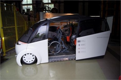
a)
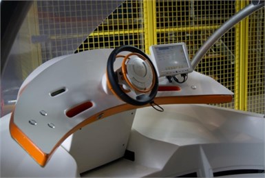
b)
The important element of of the eco-car is the circular multifunctional steering wheel (Fig. 2) that allows the driving of the car with the upper limbs only. The steering wheel is one of the elements of the “drive by wire” system that was used in the Eco-car. This means that the traditional mechanical connections (between the steering wheel and the wheel turning mechanism or between the brake pedal and the wheel braking mechanism) were replaced by using electrical or electro-mechanical systems for performing various vehicle functions. This solution is a fundamental part of the design inter alia due to allow the parameterization of the steering system (e.g. an analysis of “steering system sensitivity” – i.e. the variability in the ratio of the steering wheel rotation to the corresponding turning angle of the turning wheels).
Preliminary tests on laboratory model of the steer-by-wire carried out with the participation of people with reduced mobility of the lower limbs showed the presence of local vibration on the steering wheel. The multifunction steering interface is an essential element in the eco-car (which connects all control functions including acceleration and deceleration), accordingly, the local vibrations are more dangerous for the process than in a traditional car, in which the control is done by the lower and upper limbs. However, it is known that drivers with lower limb disabilities may have minimal difficulty in gripping the steering wheel. Therefore, simulation studies should determine whether it is reasonable to limit the turning range of the car’s steering wheel. It is assumed that a disabled driver will not be able to turn the steering wheel with the same speed as an able-bodied driver.
3. The driver model
This chapter presents simulation studies of the driver-vehicle-road system and the research will address the double lane change maneuver (“moose test”). Research in the driving process task is divided into the kinematics and dynamics analysis. The purpose of testing the vehicle’s kinematics, prior to testing the its dynamics, is to estimate the minimum velocity values in turning the steering wheel, resulting in a positive test result. The dynamics simulation studies are more important and in the case of our car, their purpose is to select a suitable structure for the electronic differential system of the drive motors as well as either examining the need to use an anti-roll bar with McPherson strut suspension or the steering force needed to turn the wheels. Currently, the “moose test” conditions are standardized in most countries but as an example it could be the German standard [1]. In literature one can also find publications containing the results of experimental studies on the analysis of the selected driver behavior during the “moose test”, i.e. an analysis of the angular speed of the steering wheel [2]. In order to retain this paper’s more manageable scope, the emphasis here is on the control aspect of the human driver and its subsequent conceptual or computer-based modelling. The function of the steering angle adjuster is performed by the “driver model” and its structure is shown in Fig. 3. The input value is a set value of the vehicle wheels’ steering angle. The adjustable steering angle relative to the chassis is subject to a time delay due to complicated human reactions, which according to various authors could include; the length of time of the signal’s reception or a decision making time lapse coupled with the motor’s reaction time length [3]. In the presented model, the decision-making duration is described indirectly as the distance travelled from the time of passing through the set point of beginning the manoeuver until the beginning of the reaction (therefore, there is no time delay in the structure of the driver model). Whereas the time of motility (turning the steering wheel through a certain angle) is related to the maximum steering wheel turning velocity υk. According to studies [2] the velocity of turning the steering wheel for the tests carried out in driving simulators produces values of 300-1200°/s ranges, when the test drive only achieves 100-300°/s. This limitation may be included in the Rate Limiter block. An inertial element (block of First Order Inertia) describes the dynamics of the steer-by-wire system. The Saturation block describes the design limitations of the adjustable steering angle of vehicle’s front wheels. The PID controller block is used for modelling the driver’s reaction to any deviation in the car’s trajectory from the desired “perfect” trajectory – Fig. 3. The task of the block is to steer the vehicle back to the desired trajectory.
The dynamic model of the examined object consists of partial models: the mechanical system, the electronic differential system for controlling the rotational velocity of the drive wheels, steer-by-wire system to change the driving direction and the steering system (the model described above). The mechanical system model is developed in accordance with the principles of MBS [4]. The model has been developed in a Matlab-SimMechanics environment. The structure of the model is described with Fig. 4: with indicated: C1-C2-S1-F – rocker arm (red), H-L-F-K – wheel carrier (blue), G, H – McPherson strut (light blue), M-K – steering gear bar (magenta). S1-S2 – anti-roll bar (green line).
Fig. 3The model structure of the steering system. Vehicle dynamics simulation during the double lane change maneuver – “moose test”

Fig. 4The structure of the McPherson strut suspension (front)
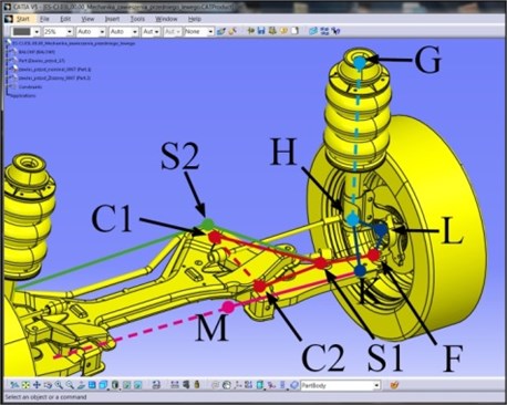
Fig. 5Block diagrams of regulating systems with velocity setting considered for applications in the designed ECO car with the infliction of a velocity difference. Marked: RW – velocity control regulator, RD – velocity difference regulator, RS – average velocity regulator, S1, S2 – electric traction motors, r1, r2 – regulators of traction motors, ωzA – the preset angular velocity of the replacement wheel at the point A of the front axle center, Δω1A, Δω2A – the preset difference of angular velocity between the replacement wheel and the first wheel, and the second wheel, ωz1, ωz2– preset angular velocity of motors, Δω12 – preset velocity difference
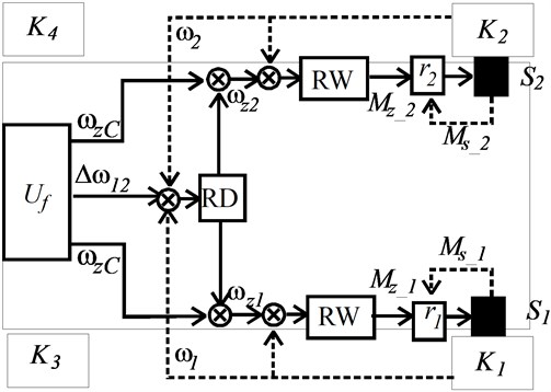
To present the dynamic properties of the tyres the TNO Delft Tyre package has been used [5] with the tyre parameters defined with the library file “TNO_car205_60R15.tir”. The solution of installing an electronic differential of propulsion motors [6], greatly affects the dynamic properties of the vehicle. Preliminary studies of dynamics simulations of the car model have shown that it is worth taking into account the following structures of motor regulatory systems: operating on speed difference for speed control or with the regulator of an average velocity in point A of the front axle of the car. The structures of the regulating systems are shown in Fig. 5 with the infliction of a velocity difference. Simulation results are presented in Fig. 6.
Fig. 6The results of driving simulation in the “moose test”. Front wheel steering angles of the driver model: Input (“reference”) and output (“resulting”)

4. Analysis of the required steering velocity of the front wheels in the moose test
The above simulation results show that the vehicle is able to pass the “moose test”. As stated above, it is assumed that the driver may, to some degree, have difficulties gripping the steering wheel, thus the analysis results of the turning velocity of the wheels should provide an answer to the question of how to adjust the maximum turning range of the steering wheel in the vehicle.
Fig. 7 shows the vehicle’s trajectory simulation results of the dynamics model. The “13” line indicates the distance of the vehicle’s central gravitational point from the road axis, in the case of limitation to the maximum velocity of turning the front wheels to the value υs=13°/s. In this case it failed to keep the vehicle within the required distance range from the road axis. The “15” line shows the velocity υs= 15°/s, line “20” – υs=15°/s, line “40” – υs=40°/s. The results show that for a steering velocity of at least υs=40°/s is required the positive test performance. For a maximum steering angle of the front wheels αmax= 35°/s, to be achieved through a 1.25 rotation of the steering wheel, the wheel would have to be turned at a velocity of at least υs=514°/s, and for a 0.5 rotation, just 206°/s.
Fig. 7The results of driving simulation in the “moose test”. Distance of the gravity center point of the car model from the road axis, for different preset values of the maximum speed of turning the steering wheel

5. Conclusions
This paper presents the transient vibration caused by lane change maneuver (called: moose test). The object of analysis was the innovative design of the eco car (equipped with, among others steer-by-wire system), the interface which consisted of multifunction steering wheel adapted for people with and without disabilities. Article demonstrated that the velocity of rotation of this wheel has extremely significant impact on the correctness of this type of maneuver. Computer simulation experiment required including it in the simulation model, the model of man. Preliminary results are very promising and the conclusions from them were used in the actual construction of Eco Car.
References
-
Driveability Testing Alliance – DTA. DTA-VDA-Ausweichtest-DE-B090602g.pdf, 2009.
-
Breuer J. J. Analysis of driver-vehicle-initeractions in an evasive manoeuvre – results of ”moose test“ studies. Daimler-Benz AG Germany, Paper Number 98-S2-W-35, 1998, p. 620-627.
-
Grabarek I. Modelling and simulation of the driver’s activity in the man-machine-environment system. Archives of Transport, Vol. 14, Issue 1, 2002, p. 5-28.
-
Blundell M., Harty D. The Multibody Systems Approach to Vehicle Dynamics. Elsevier Butterworth-Heinemann, 2004.
-
TNO Automotive Tyremodels. MF-Tyre and MF-Swift 6.1, User manual, The Netherlands, http://www.delft-tyre.nl/, http://www.automotive.tno.nl, 2008.
-
Gair S., Cruden A., McDonald J., Hredzak B. Electronic differential with sliding mode controller for a direct wheel drive electric vehicle. Proceedings of the IEEE International Conference on Mechatronics, 2004, p. 98-103.
