Abstract
The major characteristic is easy to produce saw chip in hard cutting process; the deformation process of chip has a huge impact on machining. Aimed at the generation of saw chip for the hardened bearing steel GCr15 in hard cutting process, the finite element model of 2D orthogonal cutting was built based on DEFORM, which made the simulation analysis on the distribution change the rule of stress field, strain field, temperature field and dynamic cutting force. Based on the method of hard cutting experiment combined with the 2D cutting finite element simulation and the chip cross-sectional microscopic analysis, this paper researched the deformation mechanism of saw chip forming process. When shear instability happened, the cutting tool squeezed the cut layer, and made the deformation and temperature higher on the tip of the cutting tool, which was easy to form the heat softening area. It appeared overload by reducing the loaded area of the chip root sliding area due to the heat softening area exist, the primary cause of saw chip formation is periodic adiabatic shear fracture for the hardened bearing steel GCr15. The deformation process of saw chip can be divided into the follow three stages: the cutting material changed trapezoid, adiabatic sheared slip, continued to slip formed chip unit.
1. Introduction
The most important characteristic is that it is easy to produce saw chip during hard cutting process, the fluctuations of the saw chip deformation could lead to periodic fluctuations of the cutting force in high frequency striking the cutting process system, inducing cutting vibration, and affecting machining precision, surface roughness, life of the tool and so on. The deformation process of chip has a huge impact on machining. So it is vital to analyze and research the characteristics of chips formation in hardened steel precision cutting.
At present, the formation mechanism of serrated chip hasn’t unified in academic circle. The main theoretical system includes adiabatic shear theory and periodic fracture theory. Komanduri etc. firstly proposed the adiabatic shearing theory in his theory, the serrated chip formation process can be divided into two stages. The first stage is respectively shear fracture that have adiabatic shear instability and lead to the shear fracture along the shear plane. The second phase is material uplift formed chip that the materials under the action of the cutting tool force and produce a small amount of plastic deformation and uplift, then finally form a chip [1, 2]. Davies and others believed that cutting speed increase reached a certain critical value would destroyed the dynamic balance state, and formation of serrated chip because of adiabatic shearing [3, 4]. T. J. Burns studied the chip morphology of hardened steel, he thought when increased the cutting speed can change the chip from the continuous chip to serrated chip. When low speed generated continuous chip, on the contrary produced serrated chip. With the change of cutting speed, serrated chip morphology change is regular [5]. Hou thought the serrated chip formation reason which was the shear deformation zone of the softening temperature and strain strengthen produce thermoplastic shear instability [6]. Barry J. and Byrne studied the serrated chip formation mechanism in turning G BS817M40 hardened steel. The results support the adiabatic shear theory, and point out that the adiabatic shear zone starts at the tip and extends to the free surface of workpiece [7]. Professor Wang Minjie at Dalian University of Technology and Dr. Duan Chun studied the adiabatic shearing behavior of serrated chip formation process in hard cutting. The formation of adiabatic shear band endured the martensite phase transformation, carbide precipitation and dynamic recrystallization process[8-10]. Professor Liu Xianli at Harbin University of Science and Technology and PhD Wen Donghui at Dalian University of Technology have taken cutting hardened bearing steel GCr15 experimental study. The results point out that the formation of serrated chip critical hardness of HRC50 [11]. Professor Wang Chengyong at Guangdong University of Technology and Dr. Qin Zhe typed serrated chip formation geometry model and pointed out that the serrated chip deformation degree determines the ease of hardened steel processing, and probed into the deformation law of serrated chip [12]. Professor He Ning at Nanjing University of Aeronautics and Astronautics has carried on the related experimental study to the adiabatic shearing behavior of high strength steel orthogonal cutting[13].
Shaw and Vyas proposed the theory of cycle of brittle fracture. They thought the serrated chip formation reason was chip from the free surface of workpiece to cutting edge extension of periodic integral fracture [14, 15]. Poulachon G. etc. studied the serrated chip formation mechanism when turning hardened steel 100Cr6. The conclusion supports periodic serrated chip formation fracture theory which the whole process of serrated chip formation is divided into four stages of [16]. Konig etc. studied the serrated chip formation mechanism when turning hardened steel. The conclusion supports the periodic fracture theory of serrated chip formation [17].
Finite element simulation technology which is introduced in the machining area used to simulate the cutting process in the 1970s. The United States Klamecki is the first who used finite element technique on the mechanism of chip formation in metal cutting processing system research in 1973 [18]. Shi and Guo used Zener Hollorn equation material model to simulate the process of cutting hardened steel, and to forecaste the cutting force, cutting heat and the generated sawtooth chip is, white layer [19, 20]. Ng and Umbrello used the model of John-Cook to establish finite element model in cutting. The simulation results with the experimental results have good consistency [21, 22].
2. The 2D cutting finite element model for hardened cutting
2.1. Geometric model and meshing
We used the FEA software DEFORM (Design Environment for Forming) to make the simulation analysis. When used the finite element model of 2D orthogonal cutting as the object of research to make the simulation analysis, the cutting parameters were mainly for the cutting thickness and the cutting speed. Took the length of simulation chip and machining deformation area into consideration, the size of workpiece was set to 0.8 mm×2 mm, when used the parallelogram plane strain unit, the bottom of workpiece was restrained, the grids were more intensive near the contact area. As shown in Fig. 1.
Fig. 1FEM simulation model of orthogonal cutting
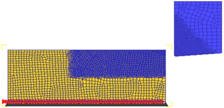
The boundary conditions are shown in figure, we set movement of the cutting tool, the way of the workpiece fixed, the environment temperature, and set the cutting temperature and the workpiece temperature for 20°C at the beginning of simulation.
Set the cutting tool for rigid body, the workpiece material for GCr15, the cutting tool materials for PCBN, the front rake angle of the cutting tool for 0 degrees, the tools back angle for 5 degrees, the cutting edges obtuse radius for 0.01 mm.
Set the cutting speed v for 200 m/min of finite element simulation, and the cutting thickness for 0.1 mm to make finite element simulation of 2D orthogonal cutting. The influence area of adiabatic shear zone was special narrow, strain gradient and temperature gradient were very large, and the insufficient grid density for which was difficult to simulate the adiabatic shear zone. When calculated, we used technology means by high-density grid division and high frequency grid redrawing, finally simulated the adiabatic shear behavior for hardened steel in cutting process and the deformation process of saw chip.
2.2. The constitutive model of workpiece material
We adopted John Cook material model, the flow stress is [23]:
where: σ is flow stress (MPa); ¯ε is equivalent plastic strain, A, B, and n are strain constants (MPa), strain hardening coefficient (MPa) and strain index; ˙¯ε is equivalent plastic strain speed, C is strain rate coefficient; ¯T is average temperature of cutting, it can be expressed as:
where: Tmelt and Troom are melt temperature and indoor temperature, m is temperature index.
2.3. The contact friction model of cutting tool and chip
We used the Coulomb friction model which was revised and commonly used in metal cutting simulation:
In the formula, τc, μ, σn, τs are critical shear force of sliding surface, friction coefficient, interface pressure, critical shear yield strength of soft materials in interface.
2.4. Grid redrawing
In order to make the convergence for calculation, we used the way of self-adaptation to make grid redrawing; it could avoid excessive distortion of the network and ensure the contact conditions between cutting tools and the workpiece.
We used the dense grid division window of the software to make the local dense division of grid in cutting area. The grid density was bigger close to the plastic deformation area and the grid density was smaller in other areas. These not only ensured the precision of the simulation calculation and can control the number of cells, but also reduced the computation time.
2.5. Fracture criterion
Fracture criterion used the Cockroft-Latham criterion:
where: Ci is fracture coefficient which is got in uniaxial tensile test; ¯σ is effective stress; σ* is maximum stress; εf is effective strain.
2.6. The calculation of temperature field
There are three heat sources in cutting process, which include the deformation plasticity of the workpiece in first deformation area, the friction of the cutting tools and chip, the friction of the cutting tools, workpiece and the surface processed. In this paper, the conversion factor and conversion efficiency factors were selected 0.9, when converted the power into heat, the friction heat came into the cutting tools and the chip respectively, we thought that the heat conduction was balanced for the generation of heat in interface, half imposed on workpiece, the other imposed on the cutting tools.
3. The finite element simulation results of saw chip forming process
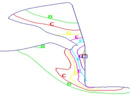
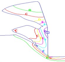
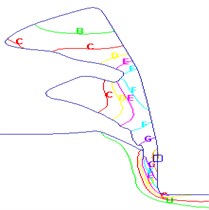
We intercepted the simulation result of six meaningful moments which were the result of a saw chip unit in all development process; these were moment a), b), c), d), e) and f). Then we got the simulation results of the equivalent stress, strain, cutting temperature and cutting force.
3.1. The simulation result of equivalent strain
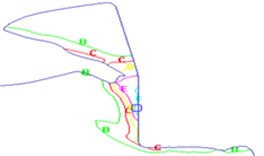
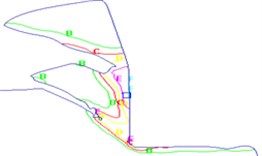
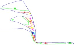
Fig. 2 shows the simulation result of equivalent strain for a saw chip unit in its development process, at the beginning of a chip unit forming, the biggest equivalent strain appeared on the tip of cutting tool, when it got to the point d), e), the biggest equivalent strain spread to the first deformation area, then formed two high equivalent strain area in the first deformation area, the interface of cutting tool and chip. At the moment when happened plastic instability in the shear plane, produced the concentrate shear slip, formed the adiabatic shear zone, and finally formed a serrated unit.
Fig. 2Equivalent strain for a unit of saw chip development process. Strain – Effective (mm/mm): A = 0.000, B = 0.506, C = 1.01, D = 1.52, E = 2.02, F = 2.53, G = 3.04, H = 3.54, I = 4.05
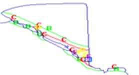
a)
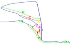
b)
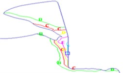
c)
d)
e)
f)
The deformation process of saw chip has two parts, the first part is adiabatic shear slip in the adiabatic shear zone, this part has a large deformation; another part of the deformation is relatively small, which is plastic deformation of chip segment internal to make the scraps surface uplift, and the parallelogram materials which need process became trapezoidal after cutting.
3.2. The simulation result of equivalent stress
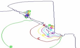
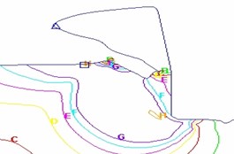
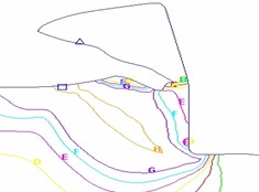
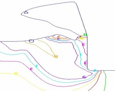
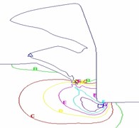
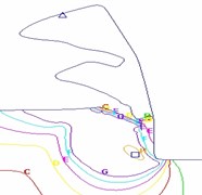
Fig. 3 shows the simulation result of equivalent stress for a saw chip unit in its development process. The initial stage a) and b) in the deformation process of saw chip unit, the biggest equivalent stress appeared on the tip of cutting tool, decreased gradually outside and distributed uniformly, in stage c) and d), the first deformation area appeared a large stress area, in the raw side of the first deformation area appeared the maximum equivalent stress, at the time d) happened adiabatic shear instability, the equivalent stress reached the material destruction stress in the first deformation area, then produced fracture, as shown in Fig. 3(e). At this time the maximum equivalent stress went back to tip area, and continued to happen plastic deformation, finally formed a unit of saw chip.
Fig. 3Equivalent stress for a unit of saw chip development process. Stress – Effective (MPa): A = 0.000, B = 187, C = 373, D = 560, E = 747, F = 933, G = 1120, H = 1310, I = 1490
a)
b)
c)
d)
e)
f)
3.3. The simulation result of cutting temperature
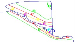
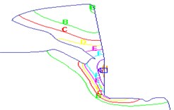
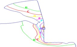
Fig. 4 shows the simulation result of cutting temperature distribution for a saw chip unit in its development process. In the early stage, the maximum temperature appeared on the tip of cutting tool and the near area which was the contact area of cutting tool and scraps, with the cutting proceeded, the first deformation area temperature raised gradually, after time d), there were a higher cutting temperature area appeared closed to the tip of cutting tool in the first deformation area, and subsequently happened plastic shear instability, there was a drop temperature process in the first deformation area, after that the temperature picked up, eventually formed a complete section saw chip.
3.4. The cutting force and cutting temperature description for a unit of saw chip development process
Fig. 5 and Fig. 6 are the cutting force simulation results for a unit of saw chip development process. The cutting temperature simulation result was close to tip of cutting tool in the first deformation area. The former in point a) was shown as serrated, it has already fully formed in point b), at the same time the surface of new chip unit began to swell under the cutting tool function, and produced a little deformation; the cutting force between point b) and point c) were in biggest area, in point c), the chip surface continued to uplift, and the sliding of chip bottom was less in rake face made the chip deformation for trapezoid, then the chip shape of this unit had basically formed, the maximum value of stress, strain rate and temperature had all appeared near the tip of cutting tool, which made the material on the tip of cutting tool soften and plastic shear instability in the shear plane, then the concentrate shear slip produced. The cutting force dropped quickly between point c) and point d), the chip unit which has slipped continued to slip under the cutting tools extrusion, the cutting force raised between time d) and time e), and in time e) the unit chip has already formed completely and the slip area of next unit chip.
Fig. 4Temperature distribution for a unit of saw chip development process. Temperature (C): A = 20.0, B = 118, C = 217, D = 315, E = 413, F = 512, G = 610, H = 708, I = 807
a)
b)
c)
d)
e)
f)
Fig. 5Cutting force simulation of saw chip development process
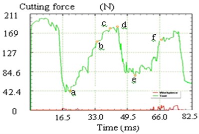
Fig. 6Cutting temperature simulation of saw chip development process
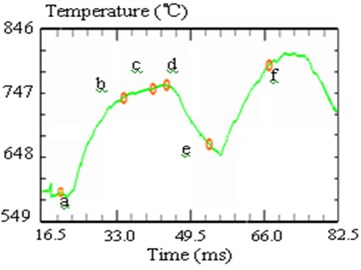
3.5. The description of simulation result at the time when happened shear instability
In point d) happened shear instability, observed the simulation results of the equivalent stress, strain, cutting temperature and the cutting force at this time, we can see the strain, the strain rate and temperature had the highest value on the tip of the cutting tool, the material on the tip of cutting tool became softened made the overload of the first deformation area dropped, then happened concentrate shear slip, after the saw chip unit formed, the cutting force dropped. The slipped chip unit continued to slip under the cutting tools extrusion, after point e) the cutting force appeared the trend of rise.
The time when happened shear instability could be described as: the cutting tool squeezed the cut layer, made the deformation and temperature higher on the tip of the cutting tool, which was easy to form the heat softening area, the overload appeared by reducing the loaded area of the root chip sliding area due to the heat softening area exist, at this time happened plastic instability.
4. The model of deformation process for saw chip
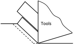
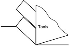
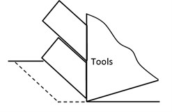
As shown in Fig. 7, the model of deformation for concentrate shear slip chip could be described the three stages as follows.
Fig. 7Model of saw chip development process
a)
b)
c)
1) The cutting material changed trapezoid: after the former chip unit has completely formed, the surface of new chip unit began to swell under the cutting tool function. The stress, strain rate and temperature increased significantly, and produced little deformation on the top of the cutting tool. The sliding of chip bottom was less in rake face, which made the chip deformation become trapezoid, then the chip shape of this unit has basically formed;
2) Adiabatic shear slip: the cutting tool squeezed the cut layer, made the temperature rise in local area, which formed the heat softening area ahead the cutting tool tip, and dropped the damage stress value of material, then happened adiabatic shear slip in adiabatic shear zone;
3) Continue to slip formed chip unit: the cutting tool continued to squeeze the cut layer material, and the chip unit which has slipped continued to slip, at the same time the slip area of next unit chip has already formed.
5. The cutting experiment of chip deformation for hardened steel GCr15
5.1. Experiment condition
The cutting experiment was made in the CA6140 engine lathe; we used the type of rigid clamping conventional cutter arbor and the basic configuration blade (rε=0.4 mm) of negative rake to cut the hardened bearing steel GCr15 by the type of external circular cutting, and studied for the characteristic of chip deformation, the Fig. 8 is the photo of experiment. We used the EMS JSM-6360LV and microscopic system KEYENCE to observe chip which was obtained in experiment.
5.2. The microscopic observation of the saw chip cross-section
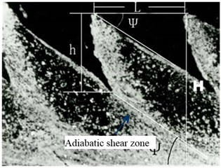
The Fig. 9 is the microstructure of saw chip cross-section; we could observe the white light adiabatic shear zone corroded clearly due to the adiabatic shear failure, the organization changed densification in adiabatic shear zone and the obvious slip line of dense distribution was shown, after the organization was stretched thin through large plastic deformation in slip line, the crack produced in direction of adiabatic shear zone.
Fig. 8Cutting experiment
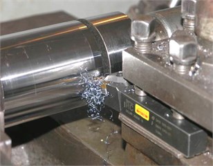
Fig. 9Microscopic observation of saw chip cross-section (×1500)
6. Conclusions
We could see that the strain, the strain rate and temperature had the highest value on the tip of the cutting tool where happened to soften made the overload of the first deformation area dropped, then happened concentrate shear slip and formed saw chip unit based on the FEA result of saw chip deformation process for the hardened steel precision cutting. At the time when happened shear instability, the cutting tool squeezed the cut layer, made the deformation and temperature were higher on the tip of the cutting tool, which was easy to form the heat softening area, made the overload appeared by reducing the loaded area of the root scraps sliding area due to the heat softening area exist, the primary cause of saw chip formation is periodic adiabatic shear fracture for the hardened bearing steel GCr15. The deformation process of saw chip can be divided into the follow three stages: the cutting material changed trapezoid, adiabatic sheared slip, continued to slip formed chips unit.
References
-
Komanduri R., Brown R. On the mechanics of chip segmentation in machining. Engineering for Industry, Vol. 130, Issue 1, 1981, p. 33-51.
-
Komanduri R., Schroeder T. A. On shear instability in machining a nickel iron base super-alloy. Engineering for Industry, Vol. 108, Issue 2, 1986, p. 93-100.
-
Davies M. A., Chou Y., Evans C. J. On chip morphology, tool wear and cutting mechanics in finish hard turning. Annals of the CIRP, Vol. 45, Issue 1, 1996, p. 77-82.
-
Davies M. A., Burns T. J., Evans C. J. On the dynamics of chip formation in machining hard metals. Annals of the CIRP, Vol. 46, Issue 1, 1997, p. 25-30.
-
Burns T. J., Davies M. A. On repeated adiabatic shear band formation during high-speed machining. International Journal of Plasticity, Vol. 18, 2002, p. 487-506.
-
Hou Z. B., Komanduri R. Modeling of thermomechanical shear instability in machining. International Journal of Mechanical Science, Vol. 39, Issue 11, 1997, p. 1273-1314.
-
Barry J., Byrne G. The mechanisms of chip formation in machining hardened steels. Journal of Engineering, Vol. 124, 2002, p. 528-535.
-
Wang Minjie, Duan Chunzheng, Liu Hongbo Experimental study on adiabatic shear behavior in chip formation during orthogonal cutting. Chinese Journal of Mechanical Engineering, Vol. 15, Issue 2, 2004, p. 243-248.
-
Duan Chunzheng, Wang Minjie Microstructure observation of adiabatic shear bands in cutting low alloy steel. Journal of Dalian University of Technology, Vol. 15, Issue 18, 2004, p. 1603-1606.
-
Duan Chunzheng Study on microcosmic mechanism of adiabatic shear behavior in orthogonal cutting of high strength steel. Ph.D. thesis, Dalian University of Technology, Dalian, 2005.
-
Wen Donghui The mechanism and technology of hard turning. Ph.D. thesis, Dalian University of Technology, Dalian, 2002.
-
Qin Zhe Studied hardened steel mechanism in high speed milling. Ph.D. thesis, Guangdong University of Technology, Guangzhou, 2009.
-
Lu Shihong, He Ning An experimental study of t he adiabatic shear behavior in orthogonal cutting of high strength steel. Mechanical Science and Technology for Aerospace Engineering, Vol. 28, Issue 2, p. 241-245, 2009.
-
Shaw M. C., Vyas A. Chip formation in the machining of hardened steel. Annals of the CIRP, Vol. 42, Issue 1, p. 29-33, 1993.
-
Shaw M. C., Vyas A. The mechanism of chip formation with hard turning steel. Annals of the CIRP, Vol. 47, Issue 1, 1998, p. 77-82.
-
Poulachon G, Moisan A. Hard turning chip formation mechanisms and metallurgical aspects. Journal of Manufacturing Science and Engineering, Vol. 8, Issue 122, 2000, p. 406-12.
-
Konig W., Berktold A. Turning versus grinding – a comparison of surface integrity aspects and attainable accuracies. Annals of the CIRP, Vol. 42, Issue 1, 1993, p. 39-44.
-
Klamecki B. E. Incipient chip formation in metal cutting – a three dimension finite analysis. Ph.D. thesis, University of Illinois at Urbana-Chanpaign, Urbana, 1973.
-
Shi J., Liu C. R. The influence of material models on finite element simulation of machining. Journal of Manufacturing Science and Engineering, Vol. 126, 2004, p. 849-857.
-
Guo Y. B., Liu C. R. Mechanical properties of hardened AISI 52100 steel in hard machining process. Journal of Manufacturing Science and Engineering, Vol. 124, Issue 1, 2002, p. 1-9.
-
Ng E. G., Tahany I., Wardany E. I., Dumitrescu M., Elbestawi M. A. Physics-based simulation of high speed machining. Machining Science and Technology, Vol. 63, 2002, p. 301-329.
-
Umbrello D., Ambrogio G., Flice L., Shivpuri R. A hybrid finite element method-artificial neural network approach for predicting residual stresses and the optimal cutting conditions during hard turning of AISI 52100 bearing steal. Materials and Design, Vol. 29, 2008, p. 873-883.
-
Mamalis A. G., Branis A. S. Modeling of precision hard cutting using implicit finite element methods. Journal of Materials Processing Technology, Vol. 123, 2002, p. 463-475.
About this article
This work was supported by National Natural Science Foundation of China (51175227) and Foundation for University Key Teacher of Heilongjiang Province of China (1252G057).
