Abstract
A theoretical model for the dynamics of composite rotor is presented. The composite shaft that includes rigid disks and is supported on rigid bearings is considered as a thin-walled Euler-Bernoulli beam. Internal damping of the composite shaft is taken into account. The equations of motion are derived using the thin-walled composite beam theory based on variational asymptotic method and Hamilton’s principle. The internal damping of shaft is introduced by adopting the multi-scale damping analysis method. Galerkin’s method is used to discretize and solve the governing equations. To demonstrate the validity of the present model, the convergence of the method is examined and the results are compared with those available in the literature. Numerical study shows the effect of design parameters on the natural frequencies, critical rotating speeds and instability thresholds of composite shaft. In addition, the free vibration responses due to the initial perturbations and the forced responses to unbalance for composite shaft are also presented.
1. Introduction
The rotating composite shaft is the primary component for helicopter power transmission and automotive drive system. This can be attributed to the improved properties of composites, such as high strength and stiffness as well as light-weight, compared to metals. On the other hand, composites have excellent damping characteristics, which make them play an important role on damping vibration of laminated plate and shell-like non-rotating structures [1]. Unfortunately, as the rotating speed is in the supercritical range, such damping may cause whirl instabilities of composite shaft. In the field of rotor dynamics, the damping in the composite shaft is called internal damping, which is also called rotating damping. Bucciarelli [2] demonstrated that increasing internal damping may reduce the instability threshold, whereas, the addition of external damping can improve rotor stability. Internal damping characteristics is very important for dynamical stability of composite shaft. Moreover, the destabilizing effect of internal damping can be easily influenced by the arrangement of the different composite layers: fiber orientation angles and number of layers. With the increasing demand for high speed composite rotors, the study of composite shaft based on accurate prediction of internal damping is becoming fundamental as it will provide more reasonable and safe rotor design.
The study of rotating shaft with internal damping was first presented by Kimball [3]. His’s results exhibited that internal damping causes shaft whirling above the first critical speed. Gunter [4] illustrated how above the first critical speed, internal viscous damping leads to instability in the rotating shaft. Vance and Lee [5] studied the stability of high speed rotors with internal viscous damping. The model they used included a single unbalance disk connected with a flexible shaft. The stability was predicted using mathematical methods and verified by numerical solutions of the equation of motion. Melanson and Zu [6] performed vibration analysis of an internally damped rotating shaft, modeled using Timoshenko shaft theory. Explicit analytical expressions for the complex frequencies and mode shapes were presented and the stability threshold was also determined. Montagnier and Hochard [7] studied dynamic instability of supercritical driveshaft with internal damping based on Euler-Bernoulli shaft model. The model taken into account the effect of translational and rotatory inertia. Simon and Flowers [8] presented an investigation of using adaptive control method to suppress instability and synchronous disturbance of a flexible shaft with internal viscous damping. However, all these foregoing literatures deal with only rotating metal shaft.
In recent years, dynamic analysis of the composite shaft with internal damping has also received some attention [9-11]. Singh and Gupta [9] presented the rotordynamic formulations which are applicable to the analysis of the composite shaft with internal damping, obtained by using a layerwise beam theory. Kim et al. [10] conducted the forced vibration analysis of a rotating tapered composite shaft. The stability of a rotating shaft driven through a universal joint has been investigated by Mazzei and Scott [11]. In the above studies, an equivalent viscous damping coefficient was introduced to account for the effect of composite internal damping, but no internal damping analysis has been proposed. To our best knowledge, very few models which incorporate damping estimations are available for predicting the dynamic behavior of composite shaft. Sino et al. [12] presented a dynamic analysis of composite rotating shaft. Internal damping was introduced by the complex constitutive relation of a viscoelastic composite.
The internal damping of composite shaft mainly comes from the dissipation of energy in the materials. Saravanos et al. [13] presented a hollow tubular beam finite element model to predict the damping properties of anisotropic thin-walled closed-section structures. However, this model is only applicable to non-rotating composite beams or blades.
An analytical model of rotating composite thin-walled shaft including internal damping is proposed. This model is based on the composite thin-walled beam theory, referred to as variational asymptotically method (VAM) by Berdichevsky et al. [14]. The internal damping of shaft is introduced via the multi-scale damping mechanics [15]. The flexible composite shaft is assumed supporting on on rigid bearings and containing of the rigid disks mounted on it. The equations of motion of the composite shaft are derived by Hamilton’s principle. Galerkin’s method is used then to discretize and solve the governing equations. The natural frequencies, critical rotating speeds, instability thresholds are obtained through numerical simulations. The effect of the ply angle is then assessed. The validity of the model is proved by comparing the results with those in literatures and convergence examination. Finally, the transient free vibration responses due to the initial perturbations and the steady state forced responses to unbalance are also obtained by using the time-integration method and the mode superposition method, respectively.
2. Composite shaft
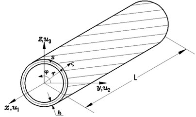
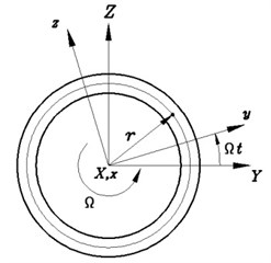
The slender thin-walled composite shaft subjected to a rotation along its longitudinal x-axis at a constant rotating speed Ω is shown in Fig. 1. The length, wall thickness and radius of the shaft are denoted by L, h and r, respectively. To describe the motion of the shaft the following coordinate systems are used: (I) (X,Y,Z)is inertial reference system whose originO is located in the geometric center, (II) (x,y,z) is rotating reference system with the common originΟ. (I,J,K) and (i,j,k) denote the unit vectors of the reference system (X,Y,Z) and (x,y,z), respectively. In addition, a local coordinate system (ς,s,x) is used, where ς and s are measured along the direction normal and tangent to the middle surface, respectively.
The variation of the strain energy of the cross-section can be expressed as:
where εTx,y={γ11γ122γ12}, γαβ(α,β=1, 2) are the in-plane tensorial strain components, A is the cross-sectional area of the shaft and ˉQij equivalent off-axis stiffness matrix of a composite ply with respect to the system οsxς.
The variation of the dissipated energy of the cross-section can be expressed as:
where ˉηij is equivalent off-axis damping matrix of a composite ply with respect to the system οsxς.
Fig. 1Geometry and coordinate systems of composite thin-walled shaft
Further, the variation of the kinetic energy of the cross-section with rotating motion is:
where diag(ρ)is a diagonal matrix with components equal to the mass density ρ of a ply.
The position, velocity and acceleration vectors for the deformed shaft are described as:
˙R=[˙u2-Ω(z+u3)]i+[˙u3+Ω(y+u2)]j+˙u1k,
¨R=[¨u2-2Ω˙u3-Ω2(y+u2)]i+[¨u3+2Ω˙u2-Ω2(z+u3)]j+¨u1k
where u1, u2 and u3 are the displacements of any point on the the cross-section of the shaft in the x, y and z directions, dot indicates the time derivative of the variable.
2.1. Equivalent cross-section stiffness matrix
To derive the strain energy and dissipated energy of the cross-section, the composite thin-walled beam theory proposed by Berdichevsky et al. [14] is employed in the following.
For the case of no internal pressure acting on the shaft, Eq. (1) can be simplified by using free hoop stress resultant assumption as:
where ∮(⋅) denotes the integral around the loop of the mid-line cross-section, and the reduced axial, coupling and shear stiffness A, B and Ccan be written as:
C(s)=4[A66-A226A22],Aij=∑Nk=1ˉQ(k)ij(zk-zk-1),i,j=1,2,6.
In Eq. (5), δUs can also be expressed with respect to the u, v, w and φ as:
where Δ is 4×1 column matrix of kinematic variables defined as ΔT=(u'φ'w''v''), and K is 4×4 symmetric stiffness matrix. Its components kij are given in Ref. [14].
2.2. Equivalent cross-section damping matrix
Similar to the derivation of the previous cross-section stiffness formulations, the variation of the dissipated energy of the cross-section [15]:
where:
Bd=Ad16+Ad61+2(A12A26A222)Ad22-(A26A22)(Ad12+Ad21)-(A12A22)(Ad26+Ad62),
Cd=4[Ad66+(A226A222)Ad22-(A26A22)(Ad26+Ad62)],
Adij=∫h/2-h/2ˉψilˉQljdς=2∑N/2k=1ˉψkilˉQklj(hk-hk-1),i,j,l=1,2,6.
The variation of the dissipated energy also be expressed in terms of the kinematic variables as:
where C is 4×4 symmetric damping matrix.
The formulation of its components cijis analogous to stiffness components kij, but the terms A, B and C in Eq. (6) should be replaced by the terms Ad, Bd and Cd in Eq. (9), respectively.
2.3. Equivalent cross-section damping matrix
Based on the displacement expressions presented in Ref. [14] and in view of Eqs. (3) and (4), the variation of the kinetic energy of the cross-section can be obtained as:
where:
I3=b1(¨w+2Ω˙v-Ω2w)+b2(¨φ-Ω2φ)-b3(2Ω˙φ+Ω2),
I4=b2(¨w+2Ω˙v-Ω2w)-b3(¨v-2Ω˙w-Ω2v)+(b4+b5)(¨φ-Ω2φ),
b1=∫Aρdsdς,b2=∫Aρydsdς,b3=∫Aρzdsdς,
b4=∫Aρy2dsdς,b5=∫Aρz2dsdς.
3. Rigid disks
3.1. Kinetic energy of rigid disks
According to Eqs. (11) and (12) the expression of variation of the kinetic energy of the rigid disks fixed to the shaft is written as:
in which:
ID3l=bD1l(¨w+2Ω˙v-Ω2w)+bD2l(¨φ-Ω2φ)-bD3l(2Ω˙φ+Ω2),
ID4l=bD2l(¨w+2Ω˙v-Ω2w)-bD3l(¨v-2Ω˙w-Ω2v)+(bD4l+bD5l)(¨φ-Ω2φ),
bD1l=∫AρDldsdς,bD2l=∫AρDlydsdς,bD3l=∫AρDlzdsdς,
bD4l=∫AρDly2dsdς,bD5l=∫AρDlz2dsdς,
where, ρDl denotes the mass density of the disk l. The symbol Δ(x-xDl) denotes Dirac delta function, ND the number of the disks mounted on the shaft and xDl the location of the lth disk.
3.2. Work of external forces
The external forces include the centrifugal force resulting from the unbalanced rigid disks. The virtual work done by the centrifugal force of rigid disks can be given by:
where, pux, puy and puz denote centrifugal force per unit length, Gux denotes centrifugal moment per unit length. They are given by:
puz=Ω2sinΩt∑NDl=1bD1lelΔ(x-xDl),Gux=0,
where, the mass unbalance associated with disks is assumed as the concentrated masses bD1l=∬ at points with small distances of eccentricity .
4. Equations of motion and approximate solution method
The equations of motion of the composite rotor can be derived by employing the following Hamilton’s principle:
In order to find the approximate solution, the quantities , , and are assumed in the form:
where , and are mode shape functions which fulfill all the boundary conditions of the composite shaft, , , and are the generalized coordinates.
Substituting Eq. (18) into the governing equations of motion, and applying Galerkin’s procedure, the following governing equations in matrix form can be found:
where is the mass matrix, is the damping matrix, is the gyroscopic matrix, the stiffness matrix. is the rotating softening matrix, is the generalized force vector. Their detailed expressions are follows:
where:
The solution for free vibration of Eq. (19) can be written in the form , from Eq. (19), one can obtain the following characteristic equation:
Complex eigenvalue can be expressed in the form:
The damping natural frequency or whirl frequency of the system is the imaginary part , whereas its real part gives the decay or growth of the amplitude of vibration. A negative value of indicates a stable motion, whereas a positive value indicates an unstable motion, growing exponentially in time.
It should be pointed out that the govering Eq. (19) is derived based on the rotating frame . In addition, for a CUS (Circumferentially Uniform Stiffness) configuration [16], Eq. (19) involving in terms of displacements can be split into two independent equation systems associated with both flapping bending-sweeping bending and extension-twist motions. The latter is important to helicopter blades. However, we will focus on the flapping bending-sweeping bending coupling only and give all numerical examples with reference to the inertial frame in this paper, the resulting govering equation are not shown for the sake of simplicity.
5. Numerical results
5.1. Model verifications
In order to examine the influence of the number of mode shape functions used in the solution of the equation on the accuracy of the results, the numerical calculations are performed by considering the shaft made of graphite-epoxy whose elastic characteristics are listed in Table 1. The shaft has rectangular cross-section of fixed width 0.32 m, wall thickness 0.01016 m and length 4.5952 m, whose layup is with clamped-free boundary conditions.
Table 1Mechanical properties of composite material [13]
(kg/m3) | (GPa) | (GPa) | (GPa) | (%) | (%) | (%) | |
1672 | 25.8 | 8.7 | 3.5 | 0.34 | 0.65 | 2.34 | 2.89 |
The numerical results of natural frequencies and modal dampings are shown in Tables 2 and 3 for an increasing number of mode shape functions. From these tables, it can be seen that to obtain the accurate results of the first two natural frequencies and dampings of flapping, sweeping and torsional mode no more than five mode shape functions are required. This indicates clearly that the convergence of the present model is quite good.
A comparison of predictions using the present model with those obtained in Ref. [13] are also shown in Table 2 and Table 3. A perfect agreement of numerical results with those in Ref. [13] can be seen.
Table 2Modal frequencies and damping of cantilever composite box beam: L/a= 14.36, a/b= 5, [90]16
Mode | Natural frequency (Hz) | Damping (%) | ||||||
Present | Ref. [13] | Present | Ref. [13] | |||||
1 | 3 | 5 | 1 | 3 | 5 | |||
First flapping | 1.80 | 1.81 | 1.81 | 1.80 | 2.39 | 2.38 | 2.38 | 2.35 |
Second flapping | – | 11.36 | 11.36 | 11.5 | – | 2.37 | 2.37 | 2.35 |
First sweeping | 5.67 | 6.20 | 6.20 | 6.50 | 3.03 | 2.53 | 2.53 | 2.35 |
Second sweeping | – | 39.21 | 39.21 | 39.7 | – | 2.36 | 2.36 | 2.37 |
First torsional | 37.83 | 37.84 | 37.84 | 37.7 | 2.89 | 2.89 | 2.89 | 2.89 |
Second torsional | 112.90 | 113.01 | 113.01 | 113.3 | 2.82 | 2.92 | 2.92 | 2.89 |
Table 3Modal frequencies and damping of cantilever composite box beam: L/a= 14.36, a/b= 5, [0]16
Mode | Natural frequency (Hz) | Damping (%) | ||||||
Present | Ref. [13] | Present | Ref. [13] | |||||
1 | 3 | 5 | 1 | 3 | 5 | |||
First flapping | 3.12 | 3.13 | 3.13 | 3.10 | 0.64 | 0.65 | 0.65 | 0.65 |
Second flapping | – | 19.02 | 19.02 | 19.8 | – | 0.69 | 0.69 | 0.67 |
First sweeping | 10.80 | 10.81 | 10.81 | 11.0 | 0.68 | 0.68 | 0.68 | 0.68 |
Second sweeping | – | 68.38 | 68.38 | 65.6 | – | 0.85 | 0.85 | 0.90 |
First torsional | 37.83 | 37.84 | 37.84 | 37.7 | 2.89 | 2.89 | 2.89 | 2.89 |
Second torsional | 112.91 | 113.01 | 113.01 | 113.3 | 2.33 | 2.92 | 2.92 | 2.89 |
Table 4Comparison of the non-dimensional natural frequencies of a rotating cantilever composite shaft
0 | 3.5160 | 3.5160 | 22.0345 | 22.0345 | 61.6973 | 61.6973 |
Ref. [17] | 3.5160 | 3.5160 | 22.0340 | 22.0340 | 61.6970 | 61.6970 |
2 | 1.5160 | 5.5160 | 20.0345 | 24.0345 | 59.6973 | 69.6973 |
Ref. [17] | 1.5160 | 5.5160 | 20.0340 | 24.0340 | 59.6970 | 63.6970 |
3.5 | 0.0160 | 7.0160 | 18.5345 | 25.5345 | 58.1973 | 65.1973 |
Ref. [17] | 0.0000 | 7.0160 | 18.5340 | 25.5340 | 58.1970 | 65.1970 |
4 | – | 7.5160 | 18.0345 | 26.0345 | 57.6973 | 65.6973 |
Ref. [17] | – | 7.5160 | 18.0340 | 26.0340 | 57.6970 | 65.6970 |
8 | – | 11.5160 | 14.0345 | 3.30345 | 53.6973 | 69.6973 |
Ref. [17] | – | 11.5160 | 14.0340 | 30.0340 | 53.6970 | 69.6970 |
The non-dimensional natural frequencies of a rotating cantilever composite shaft obtained using the present model together with those obtained in Ref. [17] are shown in Table 4 for different non-dimensional rotating speeds. A perfect agreement of numerical results with those in Ref. [17] can be seen.
5.2. Results and discussion
In the following numerical example, the composite rotor system is a composite shaft with one rigid disk supported by two rigid bearings at the ends, the disk is at the mid-point of the shaft. The material properties of the composite shaft are those in Table 1. The stacking sequence is . The length, the radius and the wall thickness of the shaft are assumed to be 2.47 m, 0.0135 m and 0.001321 m, respectively whereas those of a uniform rigid disk are 2.4364 kg, 5×10⁻⁵ m, 0.1901 kg/m2. The rotor system is shown in Fig. 2.
Fig. 2A composite shaft-rigid disk with rigid bearings
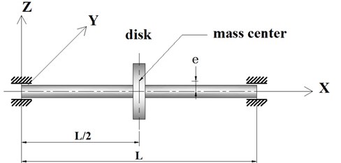
Fig. 3 shows the variation of the first two flexural natural frequencies vs. rotating speed for various ply angles, where, 1F denotes the first forward mode whereas 2F denotes the second forward mode. The synchronous whirl line is also presented in the same figure which is the well-known Campbell diagram. The intersection point of the line and the flexural natural frequency curves is referred to as the critical speed. The motion corresponding to positive flexural natural frequencies are in forward mode. The backward mode branch of the Campbell diagram with negative value of frequencies is on the lower half -plane and is symmetrical with respect to the axes. The curves corresponding to negative frequencies are not shown in this figure for the sake of simplicity.
Fig. 3The Campbell diagram of a composite rotor for various ply angles
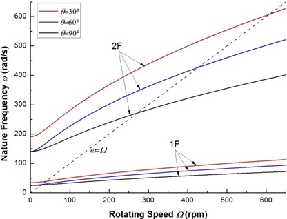
From Fig. 3, it is seen that in the inertial frame, natural frequencies of the rotating composite rotor become function of rotating speed as flapping bending and sweeping bending motions are coupled due to the presence of internal damping (there is no the Corilois effect in the inertial frame). In fact, natural frequencies of a rotating shaft are constant at all rotating speeds in the inertial frame if the influence of internal damping is not considered. The reason is that for the rotating shaft of circular section, the displacement and acceleration vectors and the elastic restoring force always have same direction [18]. As seen in Fig. 3, the effect of the ply angle and rotating speed appear to be more significant for the higher-mode ones.
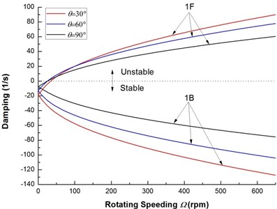
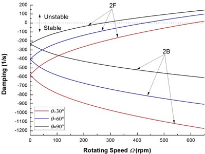
Fig. 4 shows the variation of the first two flexural dampings vs. rotating speed for various ply angles. It can be seen clearly that as the rotating speed is increased, the dampings of the backward modes decrease and remain negative for all rotating speed, so the backward modes are stable. From the results of Fig. 4, it can be also observed that the dampings corresponding to the forward modes are negative at low rotating speed and increase with increasing rotating speed, and at certain value of rotating speed the dampings vanish and then become positive. Transformation of dampings from negative to positive values marks the onset of unstable motion. The rotating speed corresponding to zero damping is the threshold of instability of the composite rotor. From Fig. 4 it seems that the effect of the ply angle on the damping of the mode 2 is more significant.
Fig. 4The decay plot of a composite rotor for various ply angles
a) Mode 1
b) Mode 2
Fig. 5Root locus of a composite rotor with internal damping
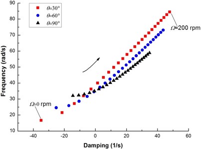
Fig. 5 shows the root locus plot of the complex eigenvalue as a function of rotating speed for various ply angles. For brevity, only the first mode is represented. In the figure the rotating speed is varied from 0.0 to 200 rpm in increments of 8.0 rpm. It is readily seen that the curve crosses the imaginary axis into the right hand side of the locus (the unstable region) with the increase of the rotating speed. It is also important to note that in the stable region, the decrease of ply angle will exert a stabilizing effect on the composite rotor, as seen by the curves with lower ply angles being further into the negative region of the locus. In contrast, in the unstable region, the decrease of ply angle promotes further instability, shown by the curves with lower ply angles being further into the right hand side of the locus.
Fig. 6 shows the effect of ply angle on the first critical rotating speed. It can be seen that as the ply angle increases, the critical rotating speed decreases and the critical speed is maximum at 0°.
Fig. 7 shows the effect of ply angle on the threshold of instability for the flexural mode. It is evident that the general effect of the ply angle on the threshold of instability is similar to that associated with the critical rotating speeds. By comparing Fig. 6 with Fig. 7, it may be noted that for the same ply angle the threshold of instability is larger than the critical rotating speed. This implies that the onset of instability always occurs after the critical rotating speed.
Fig. 6The variation of the first critical speed with ply angle
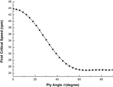
Fig. 7The variation of thresholds of instability with ply angle
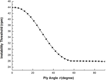
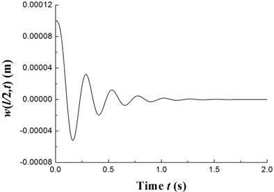
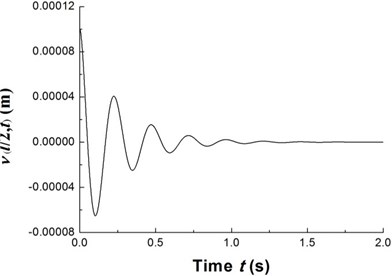
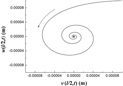
Fig. 8The time history of deflections and the trajectories of the geometric center of the rigid disk (Ω= 20 rpm)
a)
b)
c)
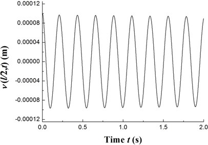
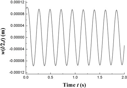
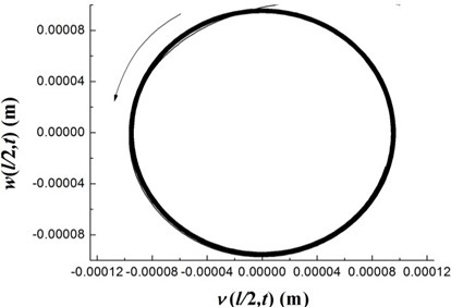
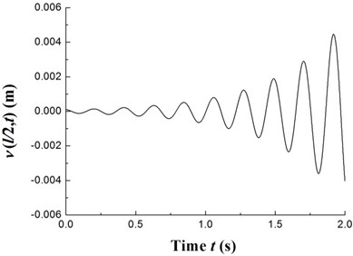
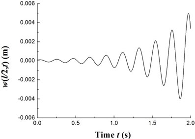
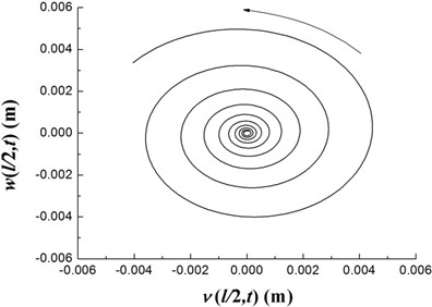
The transient responses for the geometric center of the rigid disk due to the initial perturbations are calculated by integrating Eq. (20) (with ) using the fourth order Runge-Kutta method. Figs. 8-10 present the time history of deflections and the trajectories of the geometric center of the rigid disk for rotating speeds 20 rpm, 27.89 rpm and 32.5 rpm, respectively. In the simulation, the ply angle 45°, and the initial conditions 10-5, 10-5, and are specified. Fig. 8 shows that at rotating speed below threshold of instability the oscillation in the two direction can be damped out by internal damping. Fig. 9 shows that when rotating speed is equal to the threshold of instability a whirling response with constant amplitude occurs as internal damping equals to zero in this case. It can also be noted from Fig. 10 that the forward mode of a supercritical composite rotor is unstable since the internal damping becomes positive in this case.
Fig. 9The time history of deflections and the trajectories of the geometric center of the rigid disk (Ω= 27.89 rpm)
a)
b)
c)
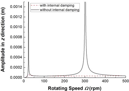
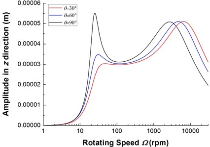
Finally, the steady state response of the composite rotor under the action of unbalance rigid disk is studied. The effect of internal damping on the steady state response is illustrated. In the simulation, the mode superposition method is used to obtain frequency response plots. Fig. 11 shows the two frequency response plots, the plot in dashed line corresponding to the case in which the internal damping are considered and the solid line corresponding to the case in which they are not. As can be seen from Fig. 11, internal damping tends to reduce resonance peak amplitude at critical speeds. This shows that the effect of internal damping on the the forced response is the same as external damping. Fig. 12 shows the effect of ply angle on unbalance steady state response with internal damping. It can be observed that the resonance peak amplitude of the lower mode is much stronger affected by internal damping, on the other hand, the effect of internal damping on the resonance frequency of the higher mode is more significant.
Fig. 10The time history of deflections and the trajectories of the geometric center of the rigid disk (Ω= 32.5 rpm)
a)
b)
c)
Fig. 11The frequency response of composite rotor with and without internal damping
6. Conclusions
A model was presented for the study of the dynamical behavior of the composite rotor with internal damping. The presented model was used to predict the natural frequencies, critical rotating speeds, instability thresholds, the transient free vibration responses and the steady state unbalance responses. Theoretical solutions of the free vibration of the system were determined by applying Galerkin’s method. From the present analysis and the numerical results, the following main conclusions were drawn:
1) The developed model provides means of predicting of the dynamic behavior of rotating composite rotors with internal damping.
Fig. 12The frequency response of composite rotor with various internal damping
2) The ply angle affect the steady state unbalance responses and instability behavior of composite rotors significantly.
3) There is an obvious decrease in the first critical rotating speed and instability threshold as the ply angle is increased. And the critical rotating speed and threshold of instability have their maximum values at 0°.
4) The onset of instability always occurs after the critical rotating speed.
References
-
Chandra R., Singh S. P., Gupta K. Damping studies in fiber-reinforced composites-a review. Composite Structures, Vol. 46, Issue 1, 1999, p. 41-51.
-
Bucciarelli L. L. On the instability of rotating shafts due to internal damping. Journal of Applied Mechanics, Vol. 49, 1982, p. 425-434.
-
Kimball Jr A. L. Internal friction theory of shaft whirling. General Electric Review, Vol. 27, 1924, p. 244-251.
-
Gunter E. J. Rotor-bearing stability. Proceedings of the First Turbo-machinery Symposium, 1972, p. 119-141.
-
Vance J. M., Lee J. Stability of high speed rotors with internal friction. ASME Journal of Engineering for Industry, Vol. 96, 1974, p. 960-968.
-
Melanson J., Zu J. W. Free vbration and stability analysis of internally damped rotating shafts with general boundary conditions. ASME Journal of Vibration and Acoustics, Vol. 120, 1998, p. 776-783.
-
Montagnier O., Hochard Ch. Dynamic instability of supercritical driveshafts mounted on dissipative supports-effects of viscous and hysteretic internal damping. Journal of Sound and Vibration, Vol. 305, 2007, p. 378-400.
-
Simon A., Flowers G. T. Adaptive disturbance rejection and stabilization for rotor systems with internal damping. Proceedings of the ASME International Design Engineering Technical Conferences and Computers and Information in Engineering Conference, IDETC/CIE, 2009, San Diego, California, USA.
-
Singh S. P., Gupta K. Composite shaft rotordynamic analysis using a layerwise theory. Journal of Sound and Vibration, Vol. 91, Issue 5, 1996, p. 739-756.
-
Kim W., Argento A., Scott R. A. Forced vibration and dynamic stability of a rotating tapered com posite Timoshenko shaft: bending motions in end-milling operations. Journal of Sound and Vibration, Vol. 246, Issue 4, 2001, p. 563-600.
-
Mazzei A. J., Scott R. A. Effects of internal viscous damping on the stability of a rotating shaft driven through a universal joint. Journal of Sound and Vibration, Vol. 265, Issue 4, 2003, p. 863-885.
-
Sino R., Baranger T. N., Chatelet E., Jacque T. G. Dynamic analysis of a rotating composite shaft. Composites Science and Technology, Vol. 68, 2008, p. 337-345.
-
Saravanos D. A., Varelis D., Plagianakos T. S., et al. A shear beam finite element for the damping analysis of tubular laminated composite beams. Journal of Sound and Vibration, Vol. 291, 2006, p. 802-823.
-
Berdichevsky V. L., Armanios E., Badir A. M. Theory of anisotropic thin-walled closed-cross-section beams. Composites Engineering, Vol. 2, Issue 5-7, 1992, p. 411-432.
-
Ren Y. S., et al. Structure damping of thin-walled composite one-cell beams. Journal of Vibration and Shock, Vol. 31, Issue 3, 2012, p. 141-146,152, (in Chinese).
-
Smith E. C., Chopra I. Formulation and evaluation of an analytical model for composite box-beams. Journal of American Helicopter Society, Vol. 36, Issue 3, 1991, p. 23-25.
-
Banerjee J. R., Su H. Development of a dynamic stiffness matrix for free vibration analysis of spinning beams. Computers and Structures, Vol. 82, 2004, p. 2189-2197.
-
Kim J. Rotation effects on vibration of structures seen from a rotating beam simply supported off the rotation axis. Journal of Vibration and Acoustics, Vol. 128, 2006, p. 328-337.
About this article
The research is funded by the National Natural Science Foundation of China (Grant Nos. 11272190), Shandong Provincial Natural Science Foundation of China (Grant Nos. ZR2011EEM031) and Graduate Innovation Project of Shandong University of Science and Technology of China (Grant Nos. YC130210).
