Abstract
Chainsaws are devices that exhibit intense dynamic effects. Their duty cycle can be divided into several stages. In particular: start-up, operational run and run-down. During each stage the motor unit is connected to or disconnected from the working part through centrifugal clutch. When driven by internal combustion motor, the unfavourable vibrations occur at the handles due to unevenness of its run. Chainsaw manufacturers pay special attention to emergency braking in critical situations. Time necessary for chain to stop from encountering the first emergency trigger is taken as a measure of effectiveness of the breaking system. To assess specific chainsaw systems, it is necessary to create detailed computational dynamic model.
1. Introduction
At the present time, the chainsaw manufacturers are not only focused on minimizing of vibration transferred to the operators’ hands, but also on effectiveness of emergency braking systems allowing rapid stop of the chain when critical conditions occur. Band brakes are used for these purposes. The braking effect depends mainly on the contact force of the band and the friction between the band and the drum. The diameter of the drum is usually driven by design requirements and cannot be arbitrarily enlarged. However, the joint action of the brake and the clutch – disconnecting the motor unit from the working unit of the chainsaw – is of particular importance. The immediate reduction of the inertial torque of the braked system leads to the significant reduction of time needed to stop the chain. The starting point of research on vibration minimizing and chain braking is a dynamic model of chainsaw. The correctly built model is particularly important for chainsaws that are powered by combustion motor. In this case –unlike the case of electric systems – not only the unevenness of the driving torque, but also the periodic variations of the moment of inertia of the moving parts have to be considered [1]. The required values of parameters of the chainsaw system can be obtained either by means of experiments or from the 3D design documentation. Determination of the driving forces lies in the measurement of pressure in the combustion chamber of the motor. The pressure is measured in dependence on angular position of the crankshaft running at different operation speeds. From these data, and from the design parameters of the crankshaft mechanism, drive torque of the motor can be obtained as a time dependent function [2].
2. Mechanical model
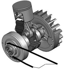
The moving parts of chainsaw involve combustion motor, flywheel with incorporated fan, centrifugal clutch drum, which is wrapped around by a band (not shown) with a wrap angle of 2π. The clutch connects the motor to the chain sprocket that drives the chain (Fig. 1).
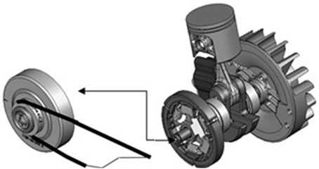
The moving assembly of the chainsaw can therefore be divided into two subassemblies; former consisting of moving motor parts with the fan and the inner part of centrifugal clutch, and the latter that comprises the outer part of the centrifugal clutch, which is the braked drum with attached sprocket and the chain (Fig. 2).
Moments of inertia JM(φM) and JS of both subassemblies are known.
Fig. 1Moving assembly of the saw

Fig. 2Two parts of moving assembly of the saw

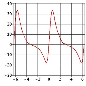
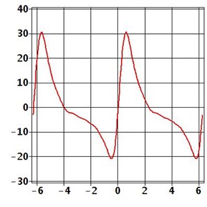
The gas pressure acts upon piston of the motor and generates the torque MM(φM), which is shown in the Fig. 3(a) as a function of the angular position of the crankshaft. The dynamic component Md(φM) is shown in the Fig. 3(b).
Fig. 3Motor torque: a) total, b) dynamic component

a)

b)
When reaching the crankshaft angular velocity ωM(t) the value ωMC, in our case is ωMC=600 rad/s, the drum with sprocket and chain starts to be connected to the crankshaft through centrifugal clutch by means of frictional joint. After that the sprocket rotates with the angular velocity ωS(t). The clutch will then transmit torque that can be calculated as Eq. (1):
where i is the number of inertial masses of the centrifugal clutch, fC is the friction coefficient between these masses and the drum, RC is their contact radius. The force FCm is given by centrifugal acceleration of one inertial mass and the force FCs represents the action of the return spring. The jump function ΨC(ωM,ωS) can have the form:
In the solved example it was taken a=0.25 and b=100.
The equations of motion of the system can be written as:
The drag torque MW(t) of the chain as a function of the square of angular velocity ωS of the sprocket can be expressed in the form:
Maximum value MWmax of this torque occurs at the highest motor speed when angular velocity ωM(t)=ωMmax(13500 rad/s); this value MWmax is equal to the average value of the motor torque MM(φM).
During braking by the band brake triggered at the time tB=2 s, the braking torque MB(t) is added to the rotating system. The value of the brake torque can be expressed as:
where RB is the radius of the braking drum, FB is the force acting on the braking band and fB is the friction coefficient between the band and the drum. The jump function ΨB(tM,ωS) can have the form:
In the solved example it was taken again a=0.25 and b=100.
Equation of motion of the chain part of the system under braking condition is now:
Fig. 4Time domain solution; velocities: a) whole assembly ωMt, ωSt, b) motor assembly ωMt, c) sprocket assembly ωSt. Moving assembly of the saw

a)

b)

c)
The system of equations of motion (3) and (8) can be solved by use of computational program such as Maple, thus getting the time domain solution of run-up and emergency brake phases (Fig. 4); with initial conditions:
3. Conclusion
Presented dynamic model of chainsaw allows examination of the formation and transmission of mechanical vibration to the operator's hands and helps effectively minimize the vibration by vibration isolation counter-measures. The model is divided into two parts; the driving and the driven one. In addition, it is possible to simulate chainsaw behaviour through its duty cycle, e.g. start-up of the engine and its connection to the chain unit via centrifugal clutch. An important finding, which can be obtained by the numerical model, is the load capacity of centrifugal clutch at a condition of peak power load of the chainsaw. Special attention is paid to the product safety by chainsaw designers. Safety of the chainsaw corresponds with the time needed for chain to be stopped by the emergency band brake. These considerations can be judged with help of developed numerical model.
References
-
Pešík L. Vančura M. Vibration of hand tool. In Proceeding of 27th International scientific Conference DIAGO. Technical University of Ostrava, 2008.
-
Pešík L., Vančura M. Antivibration system of hand-held tools with dominant vibration component. In 48th International Conference of Machine Elements and Mechanisms Department, Slovak University of Technology in Bratislava, 2007.
