Abstract
Shock wave energy generated by a blast can cause severe damage to buildings, as well as result in the loss of lives and properties. As explosive becomes increasingly powerful, the damaging effects generated by blast waves have become a weapon, not only on the battle field. Even explosions of gas utilized in various industries can be a source of great threat and destruction. Therefore, the study of the blast stress wave under the dynamic loading effect of an explosion is a subject to be carefully considered before construction planning and design, and research in this field is urgently needed. This study adopts the methods of field blasting experiment and numerical simulation analysis to analyze the shock wave energy and its attenuation characteristics by comparing the experimental results with data from the numerical simulation. The numerical analysis utilizes the Arbitrary Lagrangian-Eulerian algorithm with a 3-dimensional (3D) solid structural model and 8-node solid elements. The results show an increasing trend for blast pressure as the amount of explosive increases. With the same amount of explosive, the blast pressure extreme shows a decreasing trend as the distance from the blast center increases. The results of this study can facilitate accurate analysis of shock wave energy of a blast, assess its destructive power and provide references for the calculation of blast safe quantity-distance for the human body, as well as for the planning of building safety zones, facility shock absorption measures and disaster prevention, in order to reduce the potential danger of blast waves and ensure the safety of human lives and properties.
1. Introduction
Blast hazard can severely damage buildings and result in losses of properties. Because of the lack of shock-resistant and blast-resistant structural design requirements in their general design specifications, existing buildings have limited blast-resistant capability. Therefore, the shock wave is a phenomenon that should receive close attention in blast research. Improved shock-resistant protection in structural design is also an important topic in construction engineering, concerning situations such as high-speed collision and explosion, in order to ensure the safety of the population when disasters strike. Research in related fields is urgently needed.
An explosion is a process of fast release of physical or chemical energy, a phenomenon caused by the fast release of energy inside a limited space within a short amount of time. When an explosion occurs, the surrounding air will instantly be filled with high-pressure and high-temperature gases. A blast wave travels outward at an extremely high speed. When a shock wave comes into contact with other objects during its transmission process, it produces a shock pressure upon the objects. When an object is subjected to a blast effect, a strong stress wave occurs within it and affects its internal stability [1-5]. A blast wave causes damage to objects primarily by its impact force. Damage to facilities, buildings and various objects caused by the impact of a blast wave is called direct damage [2]. Near the blast center, an air shock wave has high speed and strength. These are key parameters in determining the effect of destruction caused by an explosion [1, 2, 6]. Scholars have adopted the energy conversion viewpoint, along with the theories of mass, energy and momentum conservation as the basis for discussing the blast wave parameters. According to the characteristics of shock waves, the effect of a blast can be analyzed by its vibration speed, acceleration, stress, displacement, etc. Therefore, analysis of the extent of hazard of near-ground and surface blasts is primarily based on the characteristics of the air shock wave [7, 8]. Kivity et al. [9] simulate an ammunition depot explosion experiment. The results indicated that, with same amount of explosive, the free-field blast pressure extreme was about 1/3 that of a surface blast. Also, when the simulation data were compared with the experimental results, the blast pressure extreme showed a 15 % relative error. Related research showed that the simulation results had higher errors near the blast center, and that the relative errors were smaller farther away from blast center [1, 4, 6, 10].
Because of its specificity and complexity, research concerning the shock wave phenomenon is conducted primarily by experiments and numerical methods to analyze the physical phenomenon of the blast. The execution of experiments can be time consuming, dangerous and costly, while numerical methods focus on obtaining parameters, as well as understanding and controlling errors. This study mainly focused on investigating explosions in the free air by analyzing the shock wave energy and the transmission characteristics of the pressure wave generated by the blast. The results can be used as a reference for rescue operations and safety protection engineering.
2. Research methods
The dynamics of the blast effect is extremely complex and should be treated as one of the geometric nonlinear, material nonlinear and contact nonlinear dynamic analysis problems. Because of the difficulty in carrying out a precise analytical analysis, research on blast effects is mostly conducted by mutual comparison and verification of experimental results and numerical analysis data. In this study, shock wave energy generated by free-field blasts was analyzed, field blasting experiments and numerical analyses were conducted and the experimental results and simulation data were mutually compared and further verified by the empirical equations of TM5-1300 [2] specifications.
2.1. Free-field blasting experiment
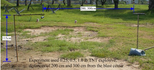
To provide a reference for comparison with data from the numerical analysis and the empirical equations, this study planned field experiments of free-field blasts. Blast pressure values were measured by a PCB 137A23 blast pressure gauge and retrieved by an Agilent oscilloscope; the data acquisition system included a signal conditioner and a power supply. Explosive was positioned 115 cm above the ground; blast pressure gauges were placed at 200 cm and 300 cm, respectively, from the blast center. Blast pressure values generated by 0.25 lb (113.389 g), 0.5 lb (226.796 g) and 1.0 lb (453.593 g) of TNT explosive were measured. The layout of the experiment site is shown in Fig. 1.
Fig. 1Field configuration scheme of blasting experiments
2.2. Numerical simulation method
This study employed hydrodynamic finite element code LS-DYNA to analyze the dynamic mechanical behaviors of a high-speed blast load. The program uses explicit time integration to process dynamic time integration problems. It also uses continuum dynamics theory as the basis for its hydrodynamic program.
2.2.1. Element type
LS-DYNA’s element types include mass element, beam element, link element, flat shell element, solid element, spring damping element, etc. This study used the Arbitrary Lagrangian-Eulerian algorithm with 3D solid elements to conduct the analysis. Elements are defined by 8 nodes. Eq. (1) is the shape function of the element [11, 12]. This type of element was used to simulate the three types of materials: soil, air and dynamite:
where ξj, ηj, and ζj are ±1 depending on different node positions.
Eqs. (2) and (3) are the stable conditions of the solid element. Eq. (4) is the characteristic length (Le) of an 8-node solid element:
The wave transmission speed of common elastic material is shown in Eq. (5), and the wave transmission speed of elastic material of a fixed volume modulus is shown in Eq. (6). The smallest time step is calculated automatically by the program during the calculation, as shown in Eq. (7):
where Q is the function of volume viscosity coefficients Ca and Cb; Le is the characteristic length; ˙εkk is the strain rate tensor; ve is the element volume; Aemax is the area at the longest side; cv is the sonic velocity in materials; ρ is the mass density; E is Young’s modulus; G is shear modulus; υ is Poisson’s ratio; and N is the number of elements.
2.2.2. Time integration
For transient finite element problems, it is better to utilize explicit time integration in the calculation process of the non-linear iterative method to avoid the convergent problem of non-linear numerical solutions. Because it uses smaller time steps, the calculation will take a relatively longer amount of time; however, because the duration of an explosion is short, smaller time steps can be used to meet its convergent conditions. Time step control, as described above, uses the smallest element to decide its value. If a time step scale factor is not set, LS-DYNA uses the smallest time step of all elements to perform the calculation; this is the conditional stability in explicit time integration. It uses the speed matrix of a known time moment in Eq. (8) to calculate its acceleration matrix, then uses Eqs. (9) and (10) to calculate the speed and displacement matrices [11, 12]:
where ¨U(tn) is the nodal acceleration matrix at tn; ˙U(tn) is the nodal velocity matrix at tn; M is the mass matrix; P(tn) is the matrix of external force vector; F(tn) is the sum of element internal force and contact force; C is the damping matrix and H(tn) is the hourglass resistance force.
2.2.3. Arbitrary Lagrangian-Eulerian (ALE) algorithm
The LS-DYNA program provides a Lagrangian algorithm, n Eulerian algorithm and an Arbitrary Lagrangian-Eulerian (ALE) algorithm. A Lagrangian algorithm is suitable for analyzing the deformation process of the material and tracking the substance particle’s time history. It can accurately describe displacements and deformation and is mainly used to analyze the stress and strain of solid structures. Its disadvantage is that the mesh will produce a severe twist deformation or negative volume in large displacement and large deformation problems and cause the calculation to stop because of numerical error. In an Euler algorithm, the mesh is independent of the object being analyzed; thus, the mesh system is fixed and will not produce a severe twist deformation. An Euler algorithm can effectively analyze the flow of fluid as well as the diffusion and mixing of gases. The disadvantage of an Euler algorithm is that the physical ratio taken up by the material in the mesh cannot be obtained easily, and that the element mesh has to cover the whole material space being described. The ALE algorithm uses Eqs. (11), (12) and (13) for the mass conservation equation, momentum conservation equation and energy conservation equation. This overcomes the disadvantages of the Lagrangian and Eulerian algorithms while keeping their advantages, i.e., improving the problem of interrupted numerical calculation caused by mesh deformation, as well as effectively controlling and tracking the movement of the boundary of the structure. It is often utilized in the dynamic real time analysis of coupled fluids and solids [13-16]:
where S(t) is a spatial region with unitary activities; ∂s(t) represents the region boundary; and vw is the velocity of ∂s(t).
3. Implementation of numerical simulation
A numerical analysis was conducted to analyze the dynamic responses of the blast waves. The scenario being considered was a free-field TNT explosive explosion, which formed a point blast center and transmitted energy outward in wave form. The actual situation was quite complicated. In the dynamic analysis, the stresses were the dynamic stresses generated by the explosion. In the analysis of free-field blast pressure extreme and its attenuation pattern, explosive and air were set up using Eulerian mesh, soil was set up using Lagrangian mesh and the ALE algorithm was used to construct the fluid-solid coupled numerical analysis model to analyze the shock wave generated by the blast. The simulation data was compared to the blast pressure duration curves from the experiment and mutually verified with data from the empirical equations of the TM5-1300 specifications.
3.1. Numerical model
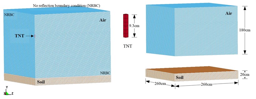
Fig. 2 show the simplified 1/4 model used in the numerical analysis. Mathematical and physical models of the free-field blast numerical analysis were planned according to the conditions of the field blasting experiment. The analysis used the ALE algorithm, with 3D Solid 164 solid elements, to conduct the simulation. The surrounding air dimensions were 260×260×180 (cm), with a non-reflective boundary to simulate a blast in unlimited space. The TNT had dimensions of 6.56×6.56×9.3 (cm), with a density of 1.63 g/cm3; dimensions of the soil were 260×260×20 (cm). The finite element mesh sizes for air, explosive and soil were 1.64 cm, 1.64 cm and 3.28 cm, respectively. The time step scale factor was set at 0.3 [11]. Numerical simulation models constructed as described above were used to analyze the free-field blast pressures at horizontal distances of 50, 100, 150 and 250 cm from the blast center, respectively, as well as the blast pressure duration curve.
Fig. 2Schematic diagram of simplified 1/4 model of free-field blast
3.2. Material parameters and equation of state (EOS)
An explosion is a highly non-linear problem with complex mechanical behaviors. The material constitutive law of the parameters is represented by the relationship between stress and strain. If the material contains a large deformation, a corresponding EOS (equation of state) should be adopted to describe the behavior of its volume change in order to realistically simulate its dynamic responses and ensure the accuracy of the analysis. EOS describes the relationships between the pressure, volume, density, temperature, volume change, material internal energy or specific internal energy of the material constitutive law.
Table 1 shows the material parameters of the TNT explosive, air and soil used in this study. According to the EOS provided in the explosive manual of the U.S. Lawrence Livermore National Laboratory (LLNL) [17], the MAT_HIGH_EXPLOSIVE_BURN material model was used to simulate the high explosive model, together with the Jones-Wilkins Lee (JWL) EOS, to describe the material behaviors of the explosive model. The equation is shown in Eq. (14). The air model also required EOS to describe its material behaviors. This study used the MAT_NULL material model, together with the EOS_LINEAR_POLYNOMIAL, to describe the air material, as shown in Eq. (15) [18]:
where A, B, R1, R2 and ω are constants representing characteristics of the explosive, V is the relative volume, E0 the initial energy of a unit volume, and Em the material internal energy:
where E0 is the initial internal energy in unit volume, μ is the coefficient of dynamic viscosity, C1, C2, C3, C4, C5, and C6 are constants and V is the relative volume.
The selection of the soil composition model should consider the porosity and its crushing and compacting behaviors, because the material, such as soil, rock or concrete, is compressible According to the above description, the MAT_SOIL_AND_FOAM was selected as the material model for the free-field blast numerical analysis [19].
Table 1Material parameters of TNT explosive, air, and soil
Element | Material and equation of state parameters (unit system: g, cm, μ-second) | ||||||
Air | MAT_NULL | ||||||
ρ | PC | μ | TEROD | CEROD | YM | PR | |
0.00129 | 0.0 | 0.0 | 0.0 | 0.0 | 0.0 | 0.0 | |
EOS_LINEAR_POLYNOMIAL | |||||||
C0 | C1, C2, C3 | C4 | C5 | C6 | E0 | V0 | |
–1.07E-06 | 0.0 | 0.4 | 0.4 | 0.0 | 2.53-06 | 1.0 | |
TNT | MAT_HIGH_EXPLOSIVE_BURN | ||||||
ρ | D | PCJ | BETA | K | G | SIGY | |
1.63 | 0.693 | 0.21 | 0.0 | 0.0 | 0.0 | 0.0 | |
EOS_JWL | |||||||
A | B | R1 | R2 | OMEGA | E0 | V0 | |
3.712 | 0.03231 | 4.15 | 0.95 | 0.3 | 0.07 | 1.0 | |
Soil | MAT_SOIL_AND_FOAM | ||||||
ρ | G | BULK | A0 | A1 | A2 | PC | |
1.8 | 0.000639 | 0.3 | 3.40E-13 | 7.03E-07 | 0.3 | –6.9E-08 | |
In the Table 1: ρ is the mass density, PC is the pressure cutoff, μ is the dynamic viscosity coefficient, TEROD is the relative volume for erosion in tension, CEROD is the relative volume for erosion in compression, YM is the Young’s modulus, PR is the Poisson’s ratio, E0 is the initial internal energy per unit reference specific volume, V0 is the initial relative volume, D is the detonation velocity, PCJ is the chapman-Jouget pressure, BETA is the beta burn flag, K is the bulk modulus, G is the shear modulus, SIGY is the yield stress.
4. Results and discussion
4.1. Blasting experiment
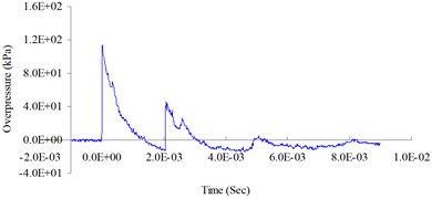
The purpose of the free-field blasting experiment was to obtain the blast pressure extreme and the attenuation characteristics of the blast wave to be used in the mutual verification of the numerical analysis and the TM5-1300 specifications’ empirical equations. Fig. 3-6 show the free-field blast pressure duration curves. The experimental results indicated a growing trend of the blast pressure as the amount of explosive increased. With the same amount of explosive, the blast pressure extreme decreased as the distance from the blast center increased. It can also be seen in the figures that the peak blast pressure showed a faster attenuation pattern with an increasing amount of explosive, and a slower attenuation pattern with an increase in distance.
Fig. 30.25 (lb) TNT blast pressure duration curve at 300 cm from the blast center, maximum peak pressure 18.00 kPa
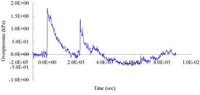
Fig. 40.25 (lb) TNT blast pressure duration curve at 200 cm from the blast center, maximum peak pressure 43.12 kPa
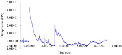
Fig. 50.5 (lb) TNT blast pressure duration curve at 200 cm from the blast center, maximum peak pressure 60.44 kPa
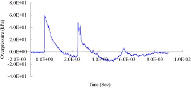
Fig. 61.0 (lb) TNT blast pressure duration curve at 200 cm from the blast center, maximum peak pressure 114.01 kPa
4.2. Dynamic finite element method
Peak blast pressures at horizontal distances (cm) of 50, 100, 150, 200 and 250 from the blast center were measured to analyze the transmission pattern of the blast wave. Fig. 7 shows the free-field blast pressure duration curves. Peak blast pressure values (kPa) were 586.77, 199.89, 133.00, 100.82 and 64.77, respectively. As can be seen in the figure, the peak blast pressure value showed a decreasing trend as the transmission distance increased.
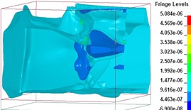
Figs. 8(a)-(f) show the free-field blast pressure wave transmission duration curves. The blast pressure wave pushed outward at a fast speed and its energy attenuation cycle was completed in several milliseconds. The blast pressure was not interfered with by a reflection wave while traveling in the air; a dynamic pressure similar to the wind pressure formed behind the blast pressure wave.
4.3. Comparison of numerical results and experimental results
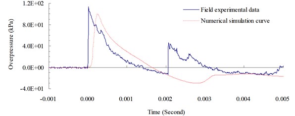
Fig. 9 shows a comparison of the blast pressure duration curves from the blasting experiment and simulation at a measuring point 200 cm from the blast center. The figure indicates that the transmission pattern of the free-field blast pressure matched the trend of the ideal blast pressure wave curve. The simulation’s peak blast pressure value of 100.82 kPa had a relative error of –11.57 % when compared to the experiment’s peak blast pressure value of 114.01 kPa. Relative error percentage (%) = (Blast pressure of numerical analysis -blast pressure of experiment) / Blast pressure of experiment × 100 %. At 200 cm from the blast center, the peak blast pressure of 109.6 kPa based on the TM5-1300 specifications’ empirical equations had a relative error of –3.87 % when compared to the peak blast pressure of the experiment. Relative error percentage (%) = (Blast pressure of the empirical equations-blast pressure of the experiment) / Blast pressure of the experiment × 100 %. Results from the numerical analysis were consistent with related literature and validated the accuracy, as well as the applicability, of the analysis and physical models in this study.
A comparison between the blast pressure duration curves from the experiments and the numerical analyses indicated that the blast pressure diffusion behavior of the explosions controlled by the EOS matched that of the experiments. The peak blast pressure had a relative error of –11.57 % and was within a reasonable range. This showed that the ALE algorithm could be used in the numerical analysis of the free-field blast to effectively analyze the pressure changes at various points during the pressure wave’s transmission process.
Fig. 7Free-field blast pressure duration curves
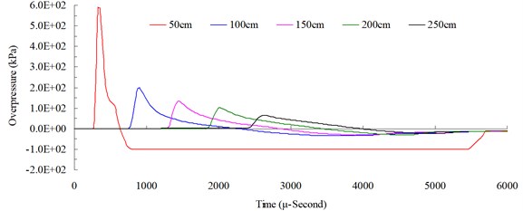
Fig. 8Free-field blast pressure wave transmission duration curves
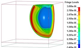
a)t=1017 μs
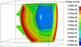
b)t=2008 μs
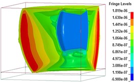
c)t=3027 μs
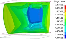
d)t=4018 μs
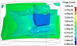
e)t=5006 μs
f)t=6000 μs
Fig. 9Blast pressure duration curves of experiment and simulation at 200 cm from the blast center
4.4. Comparison with TM5-1300 specifications
Fig. 10 shows a comparison of the peak blast pressure value between results from the simulation and the TM5-1300 empirical equations. Relative error percentage (%) = (Blast pressure of numerical simulation-blast pressure of empirical equations) / Blast pressure of empirical equations × 100 %. At a distance of 50 cm from the blast center, the peak blast pressure value of 586.77 kPa from the simulation had a relative error of –74.887 % when compared with the peak blast pressure value of 2,336.5 kPa from the empirical equations. When the distance was increased to 250 cm, the relative error (of peak blast pressure 69.3 kPa) dropped to only –6.537 %, which showed that the blast pressure from the simulation near the blast center could contain large errors. While the results from the simulation did not match that of the empirical equations exactly, they were basically consistent with the objective facts. The difference was caused mainly by the complexity of the explosion and the experimental conditions of the empirical equations. The overall trend was consistent with the attenuation characteristics of the shock wave energy.
Fig. 10Peak blast pressure values from numerical analysis and empirical equations
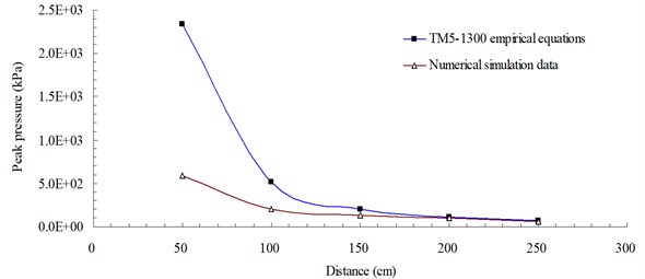
As described above, the results of this study showed that the free-field blast pressure at 200 cm from the blast center had an experimental value of 114.01 kPa, an empirical equation value of 109.6 kPa and a numerical analysis value of 100.82 kPa. The field experiment produced the highest pressure value and the numerical analysis produced the lowest pressure value. Therefore, it is recommended that data values from the numerical analysis should be adjusted by a proper magnification factor when used as a reference in blast-resistant engineering planning and design.
5. Conclusions
When explosions occur, the powerful shock wave transmitted to target objects by the flow of air affects the surrounding environment, facilities and personnel differently. This study, from the perspective of safety and disaster prevention, analyzed the transmission characteristics and attenuation pattern of the free-field blast wave and examined the shock wave effect and corresponding safety distance. Results of this study could be applied in determining safety distance and serve as a reference in safety protection design. The numerical simulation can eliminate the dangers associated with the blasting experiments. The use of a reasonably constructed numerical analysis model and a physical model, verified by the mutual verification of experimental results and simulation data as the basis for the blast analysis.
The results of this study confirmed that numerical analysis using the Arbitrary Lagrangian-Eulerian algorithm, with a 3D solid structural model and 8-node solid elements, could effectively analyze the shock wave energy generated by a blast. The results indicated that the blast pressure showed an increasing trend with an increasing amount of explosive; with same amount of explosive, the blast pressure extreme showed a decreasing trend as the distance from the blast center increased. However, data values from the numerical analysis should be adjusted by a proper magnification factor according to specific requirements when used as a reference in the design and planning of blast-resistant engineering and blast safe quantity-distance in order to minimize potential hazards caused by explosive.
References
-
Henrych J. The Dynamics of Explosion and its Use. Elsevier Scientific Publishing Company, New York, 1979.
-
Structures to resist the effects of accidental explosions, technical manual TM5-1300. US Army Engineers Waterways Experimental Station, Washington, DC, 1990.
-
Fundamental of protection design for conventional weapons, technical manual TM 5-855-1. US Army Engineers Waterways Experimental Station, Washington, DC, 1998.
-
Wu C. Q., Hao H. Modeling of simultaneous ground shock and airblast pressure on nearby structures from surface explosions. International Journal of Impact Engineering, Vol. 31, 2005, p. 699-717.
-
Lu W., Yang J., Chen M., Zhou C. An equivalent method for blasting vibration simulation. Simulation Modelling Practice and Theory, Vol. 19, 2011, p. 2050-2062.
-
Chapman T. C., Rose T. A.,Smith P. D. Blast wave simulation using AUTODYN2D: A parametric study. International Journal of Impact Engineering, Vol. 16, 1995, p. 777-787.
-
Stein L. R., Gentry R. A., Hirt C. W. Computational simulation of transient blast loading on three-dimensional structures. Computer Methods in Applied Mechanics and Engineering, Vol. 11, 1977, p. 57-74.
-
Jialing L. Numerical simulation of shock (blast) wave interaction with bodies. Communications in Nonlinear Science and Numerical Simulation, Vol. 4, 1999, p. 1-7.
-
Kivity Y., Shafri D., Ben-Dor G., Sadot O., Anteby I. The blast wave resulting from an accidental explosion in an ammunition magazine. International Symposium on Military Aspects of Blast and Shock Conference, Canada, 2006.
-
Klomfass A. Numerical investigation of fluid dynamic instabilities and pressure fluctuations in the near field of a detonation. Proceeding of the 20th International Symposium on Military Aspects of Blast and Shock Conference, Norway, 2008, p. 1-13.
-
LS-DYNA Theoretical Manual. Livermore Software Technology Corporation, 1998.
-
LS-DYNA Theory Manual. Livermore Software Technology Corporation, 2006.
-
Cook R. D., Malkus D. S., Plesha M. E. Concepts and Applications of Finite Element Analysis. John Wiley & Sons, Inc., London, 1989.
-
Benson D. J. Computational Methods in Lagrangian and Eulerian Hydrocodes. Dept. of AMES R-011 University of California, San Diego La Jolla, CA 92093, 1990.
-
Attaway S. W., Bell R. L., Vaughan C. T., Goudy S. P., Morrill K. B. Experiences with coupled codes for modeling explosive blast interacting with a concrete building. Proceedings of the Workshop on Coupled Eulerian and Lagrangian Methodologies, 2001.
-
Wang Y. T., Zhang J. Z. An improved ALE and CBS-based finite element algorithm for analyzing flows around forced oscillating bodies. Finite Elements in Analysis and Design, Vol. 47, 2011, p. 1058-1065.
-
Dobratz B. M. LLNL Explosive Handbook Properties of Chemical Explosives and Explosive Simulants. Lawrence Livemore National Laboratory, 1981.
-
LS-DYNA Version 971 User’s Manual. Livermore Software Technology Corporation, 2007.
-
Wang J. Simulation of Landmine Explosion Using LS-DYNA 3D Software: Benchmark Work of Simulation in Soil and Air. Aeronautical and Maritime Research Laboratory DSTO-TR-1168, 2001.
About this article
This study was partially supported by the National Science Council in Taiwan through Grant NSC 102-2218-E-145-001.
