Abstract
Special operation requirements are needed for repositing broken strands of extra-high-voltage (EHV) power transmission lines before repairing. Metamorphic mechanism is applied to satisfy the requirements and a novel structural synthesis method is proposed, considering the forms and structures of constrained metamorphic joints. Metamorphic cyclogram and equivalent resistance gradient matrix of metamorphic joints are obtained by analyzing the repairing operation. Meanwhile, the source metamorphic mechanism with structure of non-constrained metamorphic joints is selected. Constrained form/structure matrix of metamorphic joints is built according to metamorphic cyclogram and equivalent resistance gradient matrix. The relation between constraint force changes of joints and form/structure of metamorphic joints is then obtained; and all the eight corresponding structures of constrained metamorphic mechanism are synthesized. One of the eight mechanisms is chosen as the broken strands reposition metamorphic mechanism, and its topological transformations of working configuration are analyzed to verify the feasibility and practicality of structural synthesis method proposed in this paper.
1. Introduction
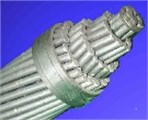
Broken strands repairing operation of EHV power transmission lines is one of the most important maintenance work of grid. At present, the most common way of repairing is still manually done by line workers on live-line, which is dangerous, costly and inefficient. In order to accomplish long-term maintenance operations and immediate repairing operations for broken lines, a live-line work mobile robot is urgently needed for the special operation condition. To develop the mobile robot repair/maintain system is one of the most available ways to solve the problems with efficiency and lower cost. The study of broken strands live-line repairing operation is still under development. The broken strands maintenance robot system was developed by IREQ in Canada 2005, and the LineScout can repair the broken strands of power transmission lines in live-line [1-2]. Currently, international researchers have done some work on live-line inspection robot to establish a research foundation for the broken strands repair robot system [3-8]. The system consists of a mobile robot and broken strands operation mechanism. Broken strands (Fig. 1(b)) must be reposited to the original form (Fig. 1(a)) before repairing. The development of broken strands reposition mechanism is one of the most important work for live-line repairing operation of EHV power transmission lines.
Metamorphic mechanism, which was first proposed a decade ago, is a variable mobility, changeable topology mechanism [9-10]. According to the required working stages and working sequences, metamorphic mechanism can change its topology to satisfy different requirements and achieve under-actuated operation by constraining the metamorphic joints of the mechanism alternately. This is based on kinematic geometry arrangements, geometric and/or force constraints, designated profiles of links and/or joints, etc [11-12]. At present, structural synthesis study of the metamorphic mechanism is more concentrated on source metamorphic mechanism and its topological transformation [13-15]. That lacks the research on obtaining forms/structures of constrained metamorphic joints and all the corresponding metamorphic configurations according to the same source metamorphic mechanism, especially structural synthesis method of practical constrained metamorphic mechanism in the special operation condition. According to the special operating and technology background of the broken strands repair process, a 2-DOF metamorphic mechanism is selected as the broken strands reposition mechanism, considering the demand of multi-mobility, under-actuated operation, specific motion requirements, and the special operation condition. Based on the changing of resistance in the metamorphic process [16], a structural synthesis method is proposed to determine the constrained forms/structures of metamorphic joints and all the corresponding metamorphic mechanisms. This research provides a reference for the structural synthesis study of practical metamorphic mechanisms.
Fig. 1a) Normal strands, b) broken strands
a)

b)
2. Operating condition
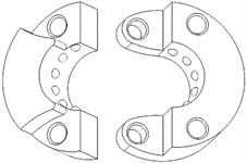
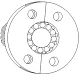
For the broken strands repair robot of EHV power transmission lines, broken strands reposition component is a kind of repositing nut with rolling element in its inner wall, which sleeves EHV transmission lines and makes the rolling element embed into the gap between adjacent strands. The process of broken strands repositing is equivalent to the meshing course between the repositing nut pushed by a mobile robot and the strands, which will complete broken strands reposition operation of lines. Because EHV transmission lines are closed, the repositing nut must be made of two cut-open nuts as shown in Fig. 2(a), which would clamp the live-line and be locked into a unite one (Fig. 2(b)) to prevent the cut-open nuts from bulging open while the mobile robot pushes them moving along the line during the broken strands reposition operation.
Fig. 2The cut-open nut
a)
b)
3. Design of source metamorphic mechanism
3.1. Operational requirements
According to the operating requirements, the reposition mechanism must be designed with 2 DOFs. One DoF is the motion of making two cut-open nuts clamp EHV power lines, the other is the motion of locking the two cut-open nuts into a united one through pins. Because of the special operation condition, it is required to reduce the weight of repair mobile robot, to simplify the control system, and to save the carrying energy (usually lithium battery). Therefore, 2-DOF constrained metamorphic mechanism is designed as the reposition mechanism which completes the two motions above with only one driver.
3.2. The design of source metamorphic mechanism
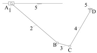
In accordance with the kinematic requirements and operating condition, the metamorphic mechanism is designed with 2 DOFs and two rotational constrained metamorphic joints. Metamorphic processes are achieved during the configuration transforming. The working statuses of constrained metamorphic joints will transfer between moving and static depended on the changing of constrained forces to form the corresponding working stages, while the diver joint and general joints keep working. The displacement (turning angle or moving distance) θ of the driver is shown in horizontal axis, and the working conditions of joints J (J=R for revolute joint, J=P for prismatic joint etc.) in corresponding working stages (or metamorphic configurations) is shown in vertical axis. The working configuration transferring and the working statuses of metamorphic joints can be described in metamorphic cyclogram as shown in Fig. 3 [16], which shows the working statuses of all the joints with the movement of driver in the corresponding working stages. Finally, the metamorphic cyclogram of 2-DOF reposition metamorphic mechanism is obtained as shown in Fig. 3. Configuration I and Configuration II denote two working configurations of the metamorphic mechanism. Suppose the driving link obtains translational motion of screw driven by a motor, a kind of corresponding planar 5-bar mechanism, i.e. source metamorphic mechanism is designed as shown in Fig. 4.
Fig. 3Metamorphic cyclogram of the metamorphic mechanism
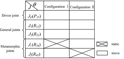
Fig. 4The source metamorphic mechanism of broken strands reposition
4. Structural synthesis method of constrained metamorphic mechanism
4.1. Equivalent resistance gradient sketch of metamorphic joints
Fig. 5Equivalent resistance gradient sketch
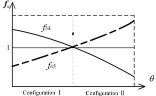
Based on Fig. 3 and equivalent resistance gradient model proposed in reference [16], the equivalent resistance gradient sketch of constrained metamorphic mechanism (Fig. 4) is obtained as shown in Fig. 5, in which fe denotes equivalent resistance coefficient and θ denotes the displacement of the driver.
The equivalent resistance gradient sketch of metamorphic joints can be described as matrix, i.e. the equivalent resistance matrix:
where, working configurations are shown in columns of the matrix, constrained status of metamorphic joints with different working configurations are shown in rows, and fij denotes that metamorphic joint Rij keeps constrained, 0 means Rij keeps working.
4.2. The structural topology matrix of constrained metamorphic mechanism
4.2.1. Constrained metamorphic joints
Typical constrained structures and constrained matrixes of metamorphic joints are shown in Fig. 6. Fig. 6(a) shows the turning joint and prismatic joint with geometric constraint which overlaps two links into one and provides infinite constraint force at the point. Fig. 6(b) shows the turning joint and prismatic joint with spring force constraint. Fig. 6(c) shows the turning joint and prismatic joint with geometric constraint controlled by spring which provides limited constraint force at the point. Fig. 6(d) shows the turning and prismatic joints with geometric constraint and spring force constraint respectively. Fig. 6(e) shows the turning and prismatic joints with geometric constraint and geometric constraint controlled by spring respectively. In constrained matrixes, 0 denotes that metamorphic joint Rij keeps moving and 1 denotes that Rij keeps static. Suppose g=r,p which denotes revolving or prismatic metamorphic joints with geometric constraints. s=rk,rt,pk,pt, where rk, rt denote revolving metamorphic joints with spring force constraint and geometric constraint controlled by spring respectively, and pk, pt denote prismatic metamorphic joints with spring force constraint and geometric constraint controlled by spring respectively. sg=rkg,rtg,pkg,ptg, which denotes metamorphic joints (revolving or prismatic) with spring force constraint and geometric constraint, and with geometric constraint and geometric constraint controlled by spring.
Fig. 6Typical constrained structures of metamorphic joints

a)g=r, p

b)s=rk, pk

c)s=rt, pt

d)sg=rkg, pkg

e)sg=rtg, ptg
4.2.2. The structural topology matrix of constrained metamorphic mechanism
In order to build the connection between constrained structures of metamorphic joints and its equivalent resistance matrixes in corresponding with working stages, structural topology matrix C of constrained metamorphic mechanism and constrained structures matrix Rij of constrained metamorphic joints are built:
In matrix C, working configurations are shown in columns and constrained structures matrix Rij of metamorphic joints are shown in rows. Compared the rows of Eq. (2) with constrained structures of Fig. 6, constrained structures matrix of metamorphic joints can be deduced:
Taking Eq. (3) into Eq. (2), structural topology matrix of constrained metamorphic mechanism is obtained:
According to Eq. (4) and permutations and combinations theory, the eight structural topology matrixes can be calculated as:
C5=[0rtrk0],C6=[0rtrt0],C7=[0rtrkg0],C8=[0rtrtg0]
There are eight constrained structures of metamorphic joints together, which means eight corresponding constrained metamorphic mechanisms can be designed theoretically to satisfy broken strands reposition operation.
4.3. Structural diagram of constrained metamorphic mechanism
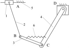
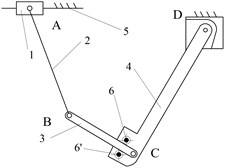
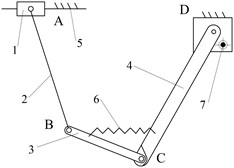
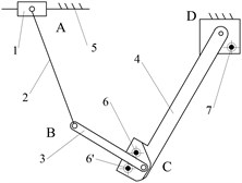
According to the structural topology matrix Ci(i= 1, 2,…, 8), the eight structural diagrams of reposition metamorphic mechanisms are illustrated in Fig. 7.
5. Structural design and working configurations analysis of the reposition constrained metamorphic mechanism
5.1. Design of the practical reposition metamorphic mechanisms and its topological transformations
The selection of the structural form is based on the reliable working configuration transforming ability and the structure simplicity. In this point of view, the mechanisms of Fig. 7(c) and Fig. 7(d) can both achieve reliable metamorphic process in metamorphic joint C. Fig. 7(c) mechanism is selected as the practical broken strands reposition metamorphic mechanism because the structure of joint C is simpler than that of Fig. 7(d). The mechanisms of Fig. 7(e)-(h) are ignored, because the form combinations of metamorphic joints with spring force constraint and geometric constraint controlled by spring are less reliable in the configuration transforming than that of Fig. 7(c). The joints C in mechanisms of Fig. 7(a) and Fig. 7(b) only have spring force constrains (no geometric constrains), which make them deselected. The mechanism in Fig. 7(c) is selected as the practical broken strands reposition metamorphic mechanism. Metamorphic joint C is spring force constraint and geometric constraint, and D is geometric constraint. Considering the symmetrical operation of practical mechanism, the practical broken strands reposition metamorphic mechanism is finally designed (Fig. 8).
Fig. 7Structural diagrams of reposition metamorphic mechanisms
a)
b)
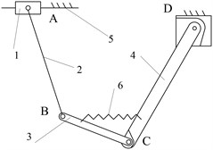
c)
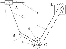
d)
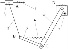
e)
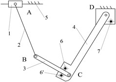
f)
g)
h)
Fig. 8The proposed broken strands reposition metamorphic mechanism

a) The main 2-mobility clamping metamorphic mechanism
b) The locking mechanism
This mechanism mainly consists of 2 parts, a main clamping metamorphic mechanism and a locking mechanism. The main clamping mechanism is a 5-bar metamorphic mechanism, which is comprised of screw nut 1, link 2, link 3, clamp 4 and the frame 0 in x-y plane (Fig. 8(a)). Cut-open nut 11 is embedded in clamp 4, and spring 10 and a geometric structure constrains joint C, and the geometric limitation (strand 12) constrains pair D. This mechanism can provide 2 motions, one for carrying two cut-open nuts clamping EHV power lines, and the other for providing driving motion (link 3) for the locking mechanism below.
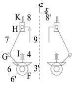
The locking mechanism is made up of crank 6, link 7, slider 8 and the frame 0 in x-z plane, which actually is a crank-slider mechanism, as is shown in Fig. 8(b). It can provide the motion of locking the two half cut-open nuts into a united one through pins. The main clamping mechanism and locking mechanism are connected through a pair of bevel gears 3’ and 6’, which are rigidly connected to link 3 and crank 6 respectively. Pin 9 is a joining pin used to lock the two half cut-open nuts, while the pin on the other side is just part of slider 8’ used to disassemble the united nut after the repairing operation.
5.2. The working configurations analysis of metamorphic process
The reposition metamorphic mechanism proposed will be carried by a mobile robot and mounted onto the EHV power line. In its initial working configuration (Fig. 9), link 3 and clamp 4 are fixed together by spring 10 and a special geometrical constraint.
When operation starts, screw 5 rotates driven by a motor, and screw nut 1 moves towards the symmetrical centre, which drives clamp 4 to swing around D to carry the cut-open nut 11 to clamp and tighten the EHV power line 12, as shown in Fig. 9.
Fig. 9The configuration of changing work stage
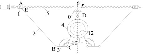
Fig. 10The locking configuration of the main clamping metamorphic mechanism
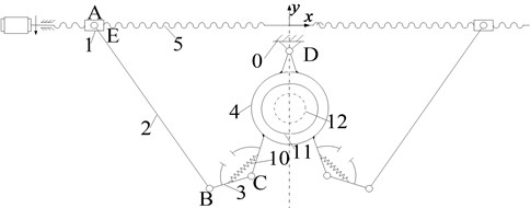
When clamping operation is finished, clamp 4 will be fixed as a part of the frame. Along with the motion of screw nut 1, link 3 begins to rotate around joint C after overcoming the spring resistance to provide a driving motion for the locking mechanism as shown in Fig. 10.
Beginning to rotate around joint C, link 3 drives bevel gear 3’ (Fi. 8(b)) to rotate relative to clamp 4 in x-z plane. Through the bevel gears 3’ and 6’ (Fig. 8(b)), movement and power are transferred to the locking mechanism which moves along with crank 6, and makes slider 8 move toward the cut-open nuts. Pin 9 connects the two cut-open nuts into a united one. The motor rotates inversely, so slider 8 moves toward the opposite direction, and joining pin 9 will remain in the pin hole. While on the right side, pin 9’ will move with slider 8’ retreating from the corresponding hole, and then the locking operation is finished. After moving back to the initial configuration, the united cut-open nut meshes with the strands to perform the reposition operation. The disassemble operation of the united cut-open nut will be done by the mechanism when the mobile robot pushes the nut to a position where the nut’s phase angle is 180°relative to the initial orientation.
6. Kinematic analysis and computational simulation
6.1. Main kinematic structure size
Table 1 shows the designed key structural parameters of the broken strands reposition metamorphic mechanism.
Table 1Kinematic parameters of the mechanism
Quantity | L0 | L2 | L3 | L4 | L6 | L7 |
Value (mm) | 15 | 120 | 25 | 80 | 25 | 35 |
Where Li denotes the length of link i, L0 represents the vertical distance from the centre of joint D to the centre of screw 5. | ||||||
6.2. Position analysis of the mechanism
6.2.1. Position analysis of the main metamorphic mechanism
Fig. 11 shows the vector diagram of the main mechanism, which is a 5-bar metamorphic mechanism in x-y plane. A closed loop vector equation can be deduced:
where, S1 is the position of slider 1. Eq. (6) can be derived according to the geometrical relationship:
+arccosL23+L24-2L3L4cosθ34+S21+L20-L222√S21+L20√L23+L24-2L3L4cosθ43,
where θ denotes the location angle of link. When the mechanism keeps in configuration I, θ3 and θ4 will be fixed relatively, and θ43=θ4-θ3=75°. However, when the mechanism keeps in configuration II, clamp 4 will be fixed as a part of the frame which means θ4 becomes a constant (255°). Thus θ3 can be calculated as:
+arccosL23+S21+L20+L24+2(S1L4cosθ4-L0L4sinθ4)-L222L3√S21+L20+L24+2(S1L4cosθ4-L0L4sinθ4).
6.2.2. Position analysis of locking mechanism
Fig. 12 shows the vector diagram of the locking mechanism, which is a crank-slider mechanism in x-z plane. A closed loop vector can be calculated as:
Eqs. (9) and (10) are deduced according to the geometrical relationship:
where, θ60=40.5358° which is the initial location angle of the crank, as is shown in Fig. 12. i3'6'=0.7, which is the transmission ratio of the bevel gear pair. According to the Eqs. (5) to (10), the relationship between S1 and S8 can be obtained, as well as functional relationships of angle θ3, θ4 and position of the slider S8 against S1, as shown in Fig. 13. The values in key points are listed in Table 2.
Fig. 11The vector diagram of the metamorphic mechanism
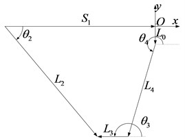
Fig. 12The vector diagram of the locking crank-slider mechanism
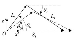
Fig. 13Relations of θ3, θ4 and S8 against S1
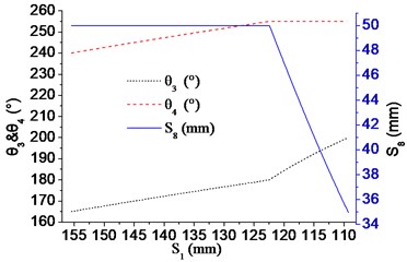
Table 2The key kinematic parameters transforming from Configuration I to Configuration II
S1 (mm) | θ4 (°) | θ3 (°) | θ6 (°) | S8 (mm) | |
Configuration I | 155.50-122.42 | 240-255 | 165-180 | 40.5358 | 50 |
Transforming | 122.42 | 255 | 180 | 40.5358 | 50 |
Configuration II | 122.42-109.27 | 255 | 180-200 | 40.5358-69.0752 | 50-34.98 |
6.3. Simulation
Practical metamorphic process (1 to 4) is simulated with a 3D modelling software package (Solidworks 2010).
1) The initial configuration of the mechanism which is carried by a mobile robot and mounted onto EHV power line is shown in Fig. 14.
2) The configuration of clamp 4 (two clamps) which carries the cut-open nuts clamping the EHV power line is shown in Fig. 15.
3) During the working Configuration II, link 3 drives bevel gears and locking mechanism to insert the pins into the holes of cut-open nuts for connecting the two cut-open nuts as a united one, as is shown in Fig. 16.
4) Slide 1 moves back and joining pins remains in the pin holes of the cut-open nuts to keep two cut-open nuts as a united one, as shown in Fig. 17. The mechanism moves back to the initial configuration, and the mobile robot can push the united nut to mesh with power transmission lines for the broken strands reposition operation, as shown in Fig. 18.
Fig. 14The initial configuration of the mechanism
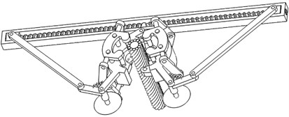
Fig. 15The cut-open nuts clamping the EHV line
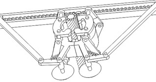
Fig. 16The locking mechanism inserts pins into cut-open nuts
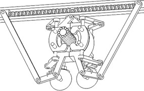
a)
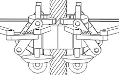
b)
Fig. 17The phase of finishing inserting the pins
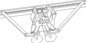
Fig. 18The configuration describing the starting of the broken strands reposition operation
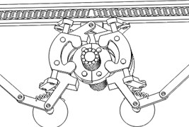
7. Conclusions
According to the special operation requirements, and the application condition of broken strands repair mobile robot used in EHV power transmission lines, a practical structural synthesis method for metamorphic mechanism is proposed. Applying the method, all the eight theoretical structures of the reposition metamorphic mechanism and forms/structures of constrained metamorphic joints are obtained. Finally, the reposition metamorphic mechanism designed can achieve multi-mobility with single-drive, which reduces the weight of the robot and save the energy carried. The results indicate that the method provides a novel way for designing broken strands repair operation mechanism of EHV power transmission lines, also for the similar design requirements of under-actuated mechanisms.
References
-
Montambault S., Pouliot N. Design and Validation of a Mobile Robot for Power Line Inspection and Maintenance Field and Service Robotics. Berlin Heidelberg, Springer, p. 495-504.
-
Toussaint K., Pouliot N., Montambault S. Transmission line maintenance robots capable of crossing obstacles, state-of-the-art review and challenges ahead. Journal of Field Robotics, Vol. 26, 2009, p. 477-499.
-
Montambault S., Pouliot N. LineScout technology: development of an inspection robot capable of clearing obstacles while operating on a live line. 11th International Conference on Transmission and Distribution Construction Operation and Live-Line Maintenance, 2006, p. 1-9.
-
Montambault S., Pouliot N. The LineScout technology: considerations for multi-span robotic teleoperated live-line inspection. 9th International Conference on Live Maintenance, Torun, Poland, 2008.
-
Wang L. D., Fang L. J., Wang H. G., Zhao M. Y. Development and control of an autonomously obstacle-navigation inspection robot for extra-high-voltage power transmission lines. International Conference on SICE-ICASE, Busan, Korea, 2006, p. 5400-5405.
-
Tang L., Fu S. F., Fang L. J., Wang H. G. Obstacle-navigation strategy of a wire-suspend robot for power transmission lines International Conference on Robotics and Biomimetics, Shenyang, China, 2004, p. 82-87.
-
Zhu X. L., Zhou J. P., Wang H. G., Fang L. J., Zhao M. Y. Experiments and Mechanism of Obstacle Negotiation of an Inspection Robot for Transmission Lines. Journal of Mechanical Engineering, Vol. 45, 2009, p. 119-125.
-
Song Y. F., Wang H. G., Ling L. Research on the influence of the driving wheel and robot posture on climbing capability of a transmission line inspection robot. 6th International Conference on Industrial Electronics and Applications, Beijing, China, 2011, p. 1632-1639.
-
Dai J. S., Rees J. Mobility in metamorphic mechanisms of foldable/erectable kinds. Journal of Mechanical Design, Vol. 121, 1999, p. 375-382.
-
Liu C. H., Yang T. L. Essence and characteristics of metamorphic mechanisms and their metamorphic ways. 11th World Congress in Mechanism and Machine Science Mechanical Engineering Press, Tianjin, China, 2004, p. 1285-1288.
-
Wang D. L., Dai J. S. Theoretical foundation of metamorphic mechanisms and its synthesis. Chinese Journal of Mechanical Engineering, Vol. 43, 2007, p. 32-42.
-
Li S. J., Zhang Y. L., Yang S., Wang H. G. Joint-gene based variable topological representations and configuration transformations. International Conference on Reconfigurable Mechanisms and Robots, London, United Kingdom, 2009, p. 348-354.
-
Li S. J., Dai J. S. Augmented adjacency matrix for topological configuration of the metamorphic mechanisms. Journal of Advanced Mechanical Design, Systems, and Manufacturing, Vol. 5, 2009, p. 187-198.
-
Li S. J., Dai J. S. Structure synthesis of single-driven metamorphic mechanisms based on the augmented Assur groups. Transactions of ASME, Journal of Mechanisms and Robotics, Vol. 4, 2012, p. 031004-1-8.
-
Li S. J., Dai J. S. The equivalent resistance gradient model of metamorphic mechanisms and the design approach. International Conference on Reconfigurable Mechanisms and Robots, Tianjin, China, 2012, p. 53-62.
About this article
The authors would like to acknowledge the financial support of the State Key Laboratory of Robotics of China (2012-O16), and the National Natural Science Foundation of China (Grant No. 51175069, 51205052).
