Abstract
This paper covers the essential information associated with recently developed piezoelectric rotary drive being able to act as the basis for most of forthcoming relevant devices. The aim of the work is to investigate such a novel table the operation of which relies on transformation of resonant ultrasonic standing wave oscillations into continuous or start-stop motion. Angular position of the device is registered by means of integrated optical encoder-type subsystem. A significant attention is paid to the structure, numerical analysis and dynamic characteristics of the drive.
1. Introduction
Due to the constantly increasing global demand for compact, high precision, low-cost angular positioning systems applied in vast areas ranging from science to military and commercial applications [1-4], it has been decided to meet the aforementioned criteria and present one of potential solutions towards this issue. While rotary piezotables currently existing on the market are mostly featured only by some of the previously stated qualities [5-7], there is still a gap in terms of optimal device.
2. Table design and operation principle
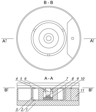
The construction discussed further in this article is basically a piezoelectric cylinder (32 mm (outer diameter) × 28 mm (inner diameter) × 14 mm (height)) incorporating sectioned electrodes for motion generation, optical encoder-type subsystem for angular position determination, and other intermediate components. Piezoceramic element PZT-4 was used because of its high resistance to depolarization and low dielectric losses even under high electric load [8]. Incremental float glass-chromium scale (64 mm×32 mm×4 mm, grating period 50 µm) combined with miniature reflective optical head unit (AEDR-8400) led to qualitative detection of angular displacement resolution. Overall structure of the table is disclosed below in Fig. 1.
When single phase high frequency signal U(t) is applied to sectioned electrodes of piezoceramic cylinder, which rests on three supporting base elements, standing wave resonant oscillations generated by the cylinder are passed to rotor via three equally displaced frictional supports. In this case ultrasonic vibrational motion featured by elliptical trajectory is induced. Rotor position with respect to its axis of rotation is ensured because of both rotor shaft, which is rigidly fixed in precise bearing, and interaction (force) between magnet and the shaft. Depending on the desired direction of motion, appropriate electrodes of piezoelement are excited. Angular position of the device is detected and identified when using rotary encoder-type subsystem consisting of incremental glass-chromium scale and displacement readout with optical head. AEDR-8400 is the smallest unit of a kind employing reflective technology for motion control purposes on the market. This optoelectronic device houses an LED light source and a photo-detecting circuitry in a single package [9].
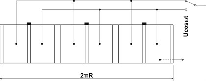
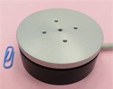
Fig. 1a) Structure of high resolution rotary table based on ultrasonic standing waves: 1 – case, 2 – supporting base elements, 3 – piezoceramic cylinder, 4 – frictional supports, 5 – rotor, 6 – rotor shaft, 7 – bearing, 8 – magnet, 9 – non-magnetic material, 10 – incremental glass-chromium scale, 11 – displacement readout with optical head; b) development and topology of piezocylinder sectioned electrodes (R – radius of piezocylinder outside); c) and d) views of rotary table
a)
b)

c)
d)
3. FEM analysis
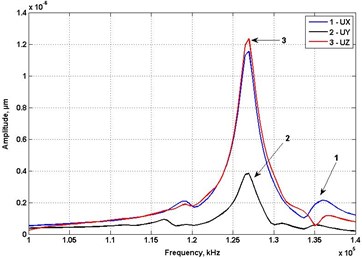
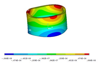
Piezoceramic cylinder modal and harmonic analyses were carried out using ANSYS software. Resonant frequency was expected to attain values in between 120 kHz and 130 kHz. However, in order not to miss other possible resonant frequencies a range of 100-140 kHz was chosen and investigated during harmonic analysis. The major results were summarized and shown in Fig. 2. The highest amplitude values of three contact points displacement with respect to X (UX), Y (UY) and Z (UZ) directions were observed at nearly 125.5 kHz. The average of displacement top amplitudes for all points is 1.15 µm in X (tangential), 0.39 µm in Y (radial) and 1.22 µm in Z (axial) direction (Fig. 2(a)). The greatest deformation and displacement of piezoelement expected to appear in the latter direction is shown in Fig. 2(b).
Fig. 2Results of piezocylinder numerical analysis: a) average of three contact points displacement amplitudes in 100-140 kHz range; b) overall body deformation in Z direction (125.5 kHz)
a)
b)
4. Experimental results
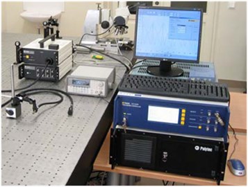
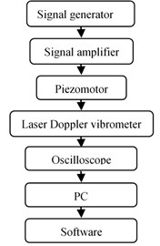
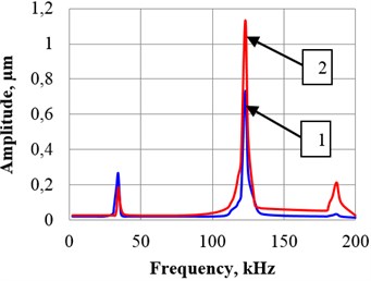
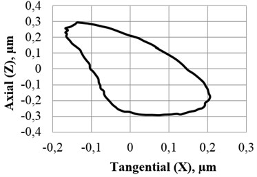
The experimental setup for measurement of trajectories of 2D vibrations with respect to the rotary table is shown and explained schematically in Fig. 3. During the measurement process employed software enabled one to extract necessary data dealing with registration of vibrations of piezoceramic cylinder unitary (singular) point in tangential and axial directions. When grouping obtained results the characteristic ellipse-like motion trajectory was formed. The same equipment was used to determine amplitude-frequency characteristics of the drive. The main results are revealed in Fig. 4.
Fig. 3Experimental setup: a) and its schematic representation, b) for measurement of amplitude-frequency characteristics and trajectories of 2D vibrations with respect to the analysed rotary table
a)
b)
Fig. 4Dynamic properties of high resolution rotary table based on ultrasonic standing waves: a) amplitude-frequency characteristics with respect to tangential (1) and axial (2) direction; b) trajectory (axial vs tangential) of 2D vibrations of unitary (singular) point (applied voltage – 70 V, excitation frequency – 124 kHz)
a)
b)
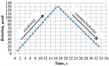
Resolution is another meaningful technical feature describing how minimally one is able to rotate the piezotable. For this to be found out nearly the same experimental stand was employed. Signal generator was set to induce vibrations in the piezocylinder by supplying 3 trigger cycles every second (voltage – 70 V) to it. Positions of the table were registered applying readout device ARCS CS 3000 and expressed in microradians by means of the following plot. Time interval from 0 to 16 s stands for clockwise motion, while interval from about 18 to 33 s is related to counterclockwise direction. Intermediate interval stands for transient process when changing direction of motion. Observed resolution attained values of 7.9 µrad and 6.9 µrad for the mentioned directions, respectively.
Fig. 5Resolution of investigated piezotable – 7.9 µrad in clockwise direction and 6.9 µrad in counterclokwise direction
5. Conclusions
Based on the results, the following conclusions are formulated:
FEM analysis indicates that resonant frequency of piezocylinder is 125.5 kHz with respect to X (tangential) and Z (axial) directions, while the average of displacement maximal amplitude values is 1.15 µm and 1.22 µm for three contact points in corresponding directions.
Piezocylinder experimental amplitude-frequency characteristics shows that values of eigenfrequency in X (tangential) and Z (axial) directions are the same (124 kHz), and maximal amplitudes are equal to 0.73 µm and 1.13 µm, respectively.
Trajectory of induced standing wave type vibrations in terms of X and Z directions attains nearly elliptical shape, what represents a qualitative and uniform rotational motion of the rotor.
Resolution of investigated piezotable is 7.9 µrad in clockwise and 6.9 µrad in counterclokwise direction, meaning that piezodrive is a non-linear system but is featured by high precision.
References
-
Kim S. H., Cho M. Y. Design and modeling of a novel 3-DOF precision micro-stage. Mechatronics, Vol. 19, Issue 5, 2009, p. 598-608.
-
Zheng J., Salton A., Fu M. Design and control of a rotary dual-stage actuator positioning system. Mechatronics, Vol. 21, Issue 6, 2011, p. 1003-1012.
-
Gao W., Sato S., Arai Y. A linear-rotary stage for precision positioning. Precision Engineering, Vol. 34, Issue 2, 2010, p. 301-306.
-
Kuo M. W., et al. Precision nano-alignment system using machine vision with motion controlled by piezoelectric motor. Mechatronics, Vol. 18, Issue 1, 2008, p. 21-34.
-
Catalogue of company PI, http://www.physikinstrumente.com/en/solutions/index_E_PDF_catalog.
-
FBR series rotary stage, Nanomotion.
-
http://www.nanomotion.com/index.aspx?id=2572&itemID=1573.
-
Attocube – pioneers of precision. Product catalog, 2012&2013, Munich.
-
Morgan electro ceramics, http://traktoria.org/files/sonar/piezoceramics/morgan/properties_of _piezoelectric_ceramics_(pzt-4_pzt-5a_pzt-5h_pzt-8).pdf.
-
Reflective encoder AEDR-8400, Avago Technologies, http://www.avagotech.com/docs/AV02-0262EN.
