Abstract
A dynamic model of offset press gear transmission system made up of gears, cylinders and bearings is proposed in this study. The model based on finite element method (FEM) includes some nonlinearity such as time-varying meshing stiffness, backlash, static transmission error and contact nonlinearity, which lead to complex nonlinear coupling. The Darren Bell principle and Lagrangian approach are applied to derive the motion equations of system, then the Newmark method is used to solve the equations for meshing force, acceleration, shoulder iron and rubber contact force. Eigenvalue solution is used to predict the critical speed, moreover, the influence of the radial and axial stiffness on the first-order critical speed is discussed. Considering the importance of acceleration and meshing force, the RMS value of acceleration and dynamic factor are also studied in this paper. The dynamic orbits of system are observed from the phase diagram, power spectrum, Lyapunov exponent and Poincare map. The figures clearly indicate that there are various forms of periodic and chaotic motions in different conditions. The simulation results show that with the increase of rotating speed, dynamic orbits transfer from periodic motion to chaotic motion in the cylinder discrete state.
1. Introduction
With the increased demand for high speed and high precision offset press, the dynamic characteristics of gear-cylinder-bearing are still a matter of considerable focus in terms of noise and vibration even though there have been many papers on this topic. Researchers paid their attention to the vibration issue on different aspects such as mathematical model, experiment and solving method.
An extensive review of gear system was given by Ozguven and House [1] in the 1980s. With the development of technology, the previous gear pair model had changed into gear-shaft-bearing model which was considered to be more accurate. Vaishya and Singh [2] established a gear pair model with sliding friction parameter and applied the Floquet theory to obtain the forced vibration response. Qiang Gao et al. [3] developed a finite element program to analyze the contact-impact behavior of gear-rotor system under high rotational speed condition. Lagrangian approach were applied to obtain the differential equations of motion for each component of dual rotor system in [4] and investigated start-up simulation. C. W. Chang Jian [5] presented a model of gear-rotor-bearing system under strong nonlinear effects (e.g. nonlinear oil-film force, nonlinear rub impact force and nonlinear gear mesh force). The results showed that there were non-periodic motion in the system under enumerative nonlinear effects. Reynolds equation for finite length journal bearing was used to computer hydrodynamic bearing force in [6], in which used to analyze dynamic behavior of gear transmission system. An Sung Lee et al. [7] built a model including lateral and torsional vibration to simulate dynamic response of gear-rotor-bearing system. Their study matched well with that of previous researches. C. H. Kang et al. [8] investigated the dynamic behaviors of gear-rotor system with the effects of transmission error and the residual shaft bow. The results showed that the magnitude and phase angle of residual bow had tremendous influence on the first-order critical speed when the system mounted on the stiff viscoelastic supports. Aydin Gunduz and Rajendra Singh [9] built a model based on the Hertz theory to obtain the stiffness matrix of double row angular contact ball bearing. The Timoshenko beam theory was employed to text the nonlinear response of spindle milling system by S. H. Gao et al. [10]. It was found that suitable constant bearing stiffness could be adopted to replace the nonlinear Hertz stiffness in prediction of the critical cutting depth.
This work is inspired by [11] and extended to further research, then shoulder iron and rubber contact condition are introduced into the model, which were usually neglected but actually very serious factors. The objective of the paper is to investigate the dynamic characteristics of gear-scylinder-bearing system to improve printing speed and quality. First, the equations of motion are derived from Lagrangian approach by assembling each component. Then, the procedure integrates FEM and the Newmark method to obtain the dynamic characteristics of system parameters such as critical speed, meshing force, acceleration, shoulder iron and rubber contact force. The effect of the radial and axial stiffness on the first-order critical speed, the RMS value of acceleration and the dynamic factor are also discussed. Finally, the nonlinear behavior of system is characterized by using the phase diagrams, power spectrum (FFT), the maximum Lyapunov exponent and Poincare map, which provide better understanding of the operating conditions.
2. Dynamic model and component equations
The configuration of gear-cylinder-bearing system is shown in Fig. 1(a). The system consists of one helical gear pair, two cylinders, four tapered roller bearings and stepped shafts. Cylinder and stepped shafts are cast into integration and the shoulder iron distribute on the ends of cylinder surface. The helical gear pairs mounted on the stepped shafts and the four tapered roller bearings supported on the frame are treated as two rigid disks and flexible elements, respectively.
Fig. 1The model of gear-cylinder-bearing system and rotor coordinates
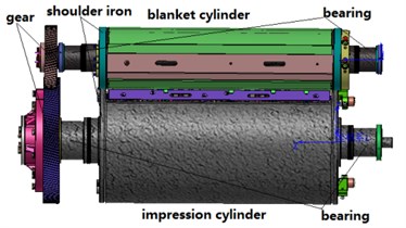
a) 3D model
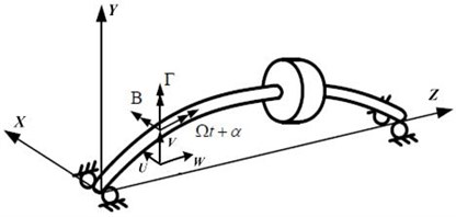
b) Rotor configuration and coordinates
As shown in Fig. 1(b), a fixed reference coordinate, X-Y-Z, is utilized to described the system motion. The six degrees of freedom U, V, W, Β, Γ, α are considered at each nodal point of the shaft, where U and V denote the lateral displacements in the X-Y directions and W denotes the axial displacement in the Z direction. Β and Γ are the rotational angles about the X-Y directions and the torsional displacement denotes by α.
2.1. Gear pair
As Fig. 2(a) shown, a three-dimensional dynamic model of helical gear pair based on [12] is extended to nonlinear model including time-varying meshing stiffness, backlash, static transmission error, eccentricity and torque ripple. The gears i and j connect to each other by a time-varying meshing spring kij(t) [13] on the plane of action. ψij is defined as the angle between the plane of action and the positive of y-axis, cij=εkave is meshing damping and β is helix angle.
Each gear has six degrees of freedom, hence a displacement vector can be defined as:
Fig. 2The dynamic model of a helical gear pair and schematic diagram of beam element
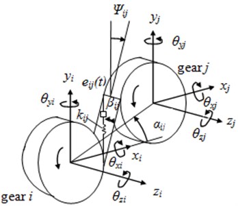
a) Helical gear pair model
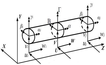
b) Timoshenko beam element and coordinates
The equations of motion for gear pair are given as:
where m, I and J(i,j) are the mass, transverse moment of inertia, rotary inertia, respectively. T(i,j) are the torque and load, r(i,j) are the radius of basic circle. The relative displacement at the gear meshing in a direction normal to contact surfaces is defined as:
+(-zi+zj+riθxisinψij+rjθxjsinψij+riθyicosψij+rjθyicosψij)sinβij-eij(t).
The time-varying meshing, the static transmission error excitation function and the torque ripple can be expressed as the discrete Fourier series:
where kave, e0 and T(i,j) arethe average meshing stiffness, the average static transmission error and the average torque of gear (i, j). kn, en, Ti0, Tj0 and γn, νn, χn, ηn are the nth harmonic amplitude and phase angle. wm and w(i,j) are the gear meshing frequency and rotating speed of gear (i, j). According to [14], R= 5 is applied in the harmonic equations.
The backlash bz can be described in three piecewise linear regimes by:
The stiffness matrix [Kg], the mass matrix [Mg], the damping matrix [Cg], the gyroscopic matrix [Gg] and the external vector [Fg] constitute the motion equations of gear pair and can be described as:
2.2. Cylinder and shaft element
In this paper, cylinders and stepped shafts considered the effects of shear deformation and gyroscopic moment are treated as Timoshenko beam. As shown in Fig. 2(b), a two-node shaft with six degrees of freedom at each nodal point is used for the finite element formulation. The kinetic energy for each beam element due to bending, shear and axial deformation is described as:
∙(˙BsΓs-˙ΓsΒs)}ds.
The strain energy of Timoshenko beam element is given by:
where ρ, A, Is and Js are the density, the area of cross-section, transverse moment of inertia and rotary inertia of the shaft, respectively. Es, Hs, Gs and ks are Young’s modulus, area moment of inertia, shear modulus and shear form factor of the shaft, respectively. The displacement vector of beam element is described as:
With Lagrangian approach, the motion equations of the shaft element can be obtained as:
where [Ms], [Cs], [Gs] and [Ks] represent the mass, damping, gyroscopic and stiffness matrices of the shaft element, respectively. [Fs] is the external force vector acting on the shaft.
2.3. Bearing
The inherent nonlinear characteristics of bearing derive from time-varying bearing stiffness, therefore the Hertz contact theory is applied to obtain tapered roller bearing stiffness matrix in various operating conditions. The motion equations of bearing and the displacement vector {qb} can be described as:
where [Mb] and [Kb] represent the mass and stiffness matrices of bearing element, damping is neglected due to weak effect on system [15]. [Fb] is the external force vector acting on the bearing.
The [Mb] and [Kb] can be obtained by several times of iterative computation in the commercial software Romax designer which has been proven to be effective [16]. The five dimensional matrix varied in different conditions includes the radial, axial and tilting stiffness.
2.4. Shoulder iron and rubber
In the process of printing, there exist two kinds of state between blanket cylinder and impression cylinder, for example, the contact state and the discrete state (Fig. 3(a)). Generally, the change of state is achieved by eccentric bearing and on-off pressure mechanism. In this section, the friction is neglect and the stress-strain relationship submits Hook’s law. Based on the assumption, shoulder iron contact is considered to be ideal Hertz contact and the load-deflection relationship is used to obtain Hertz contact stiffness. By means of formulation derivation, the shoulder iron contact stiffness can be described as:
where L is contact width. Vi, Ri and Ei (i= 1, 2) are Poisson’s ratio, radius of curvature and elasticity modulus, respectively. R is composite radius of curvature and d is pressed depth.
Fig. 3Schematic of cylinder contact and the rubber contact stiffness
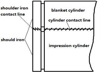
a) Schematic of cylinder contact
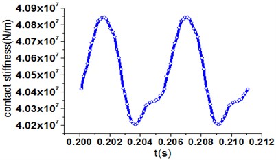
b) The rubber contact stiffness
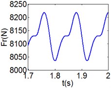
Due to strong nonlinearity, the rubber contact model [17] was built in NASTRAN software to simulate the contact process. The rubber contact stiffness Kr is obtained by analysis of load-deflection relationship. As Fig. 3(b) shown, Kr is a periodic function of time, therefore, FFT to the discrete data is implemented by using spline interpolation. Kr can be described as:
where Aave, Am, wr and κm are the average value, the mth harmonic amplitude, the fluctuation frequency and phase angle, respectively. u is equal to 5 just like [14].
2.5. Assembly and system equations
The assembly finite element model is shown in Fig. 4(a), it has 18 nodes in total and accordingly a total of 108 degrees of freedom. By assembly equations of each component, the motion equations of system can be expressed as:
where [M], [C], [G] and [K] represent the system mass, damping, gyroscopic and stiffness matrices, respectively. [F] is the external force vector due to mass eccentricity, static transmission error, motor torque and load.
Fig. 4The assembly finite element model and ANSYS model
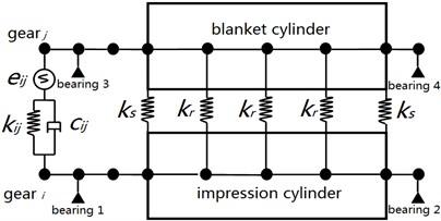
a) Finite element model of system
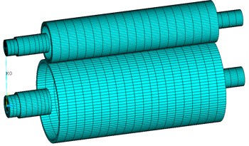
b) ANSYS model
3. Results of numerical simulation
To demonstrate the mathematical model and the efficiency of solving method, numerical simulation was carried out to obtain the critical speed, steady state response and dynamic characteristics. Due to limited space, a complete list of all parameters involved is not feasible. Therefore, Table 1 and 2 only list a small number of significant parameters of gear pair and bearings (in 15000 revolutions per hour).
Table 1Parameters of gear pair and bearings
Gear | i | j | Bearing (15000 r/h) | 1 | 2 | 3 | 4 |
mn (mm) | 4 | 4 | kxx (N/m) | 2.534E9 | 5.722E8 | 3.369E9 | 1.606E9 |
z | 140 | 70 | kyy (N/m) | 1.868E9 | 5.702E8 | 2.459E9 | 1.613E9 |
β(°) | 15.09 | 15.09 | kzz (N/m) | 3.088E8 | 6.056E7 | 4.219E8 | 2.330E8 |
m (kg) | 90.96 | 17.6 | kθxθx (N·m/rad) | 5.989E4 | 8.129E4 | 1.288E5 | 5.385E4 |
I (kg·m2) | 2.42 | 1.106 | kθyθy (N·m/rad) | 8.667E4 | 8.147E4 | 2.378E5 | 5.323E4 |
J (kg·m2) | 5 | 0.2 | kθzθz (N·m/rad) | 0 | 0 | 0 | 0 |
Table 2Parameters of gear meshing
Kave (N/m) | Aave (N/m) | e0 (um) | cij (N·s/m) | bz (mm) |
1.277E9 | 4.05E7 | 2 | 1.28E4 | 0.24 |
As Table 1 listed, the stiffness kxx(kθxθx) and kyy(kθyθy) are not the same, the phenomenon reveals that bearing stiffness based on Hertz contact theory can accurately reflect the roller deformation in different directions.
3.1. Effect of stiffness on the critical speed
The first-order nature frequency of system is zero due to the rigid body motion in the rotation direction. After neglecting the damping, gyroscopic moment and external force, Eq. (19) is rearranged to determine the eigenvalues and eigenvectors. The eigenvalues are equal to the critical speeds and the eigenvectors are related to the mode shapes. As Fig. 4(b) shown, a more accurate ANSYS model, including the beam, spring, bearing and mass elements, is used to compute nature frequencies with the Block Lanczos method, and then we make a comparison between the mathematical model and the ANSYS model.
Table 3The first ninth critical speeds of system
Order | 1 | 2 | 3 | 4 | 5 | 6 | 7 | 8 | 9 |
Mathematical model (r/s) | 98.8 | 157.1 | 167.2 | 178.5 | 192.0 | 213.1 | 277.4 | 383.7 | 418.5 |
ANSYS (r/s) | 101.3 | 152.4 | 174.3 | 186.4 | 199.7 | 228.2 | 293.6 | 364.8 | 393.2 |
ε% | 2.47 | 3.08 | 4.07 | 4.53 | 3.86 | 6.62 | 5.52 | 5.19 | 6.43 |
The first ninth critical speeds of system are displayed in Table 3 and an excellent agreement is observed, the relative error (ε %) is less than 7 % for the first ninth critical speeds. In contrast, the relative error of high order critical speeds are greater than the low order’s.
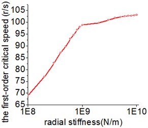
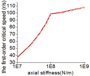
In general, the stiffness of supports has a great effect on the dynamic performance of system. Fig. 5 presents the relationship between the bearing stiffness and the critical speed. It is obvious that the radial and axial stiffness have a similar effect trend on the first-order critical speed. The first-order critical speed is easy to be changed when the stiffness alters within a certain range. In addition, the effective range of the radial stiffness is about ten times the value of the axial stiffness.
Fig. 5The influence of the radial and axial stiffness on the first-order critical speed
a) Radial stiffness
b) Axial stiffness
3.2. RMS value of acceleration and dynamic factor
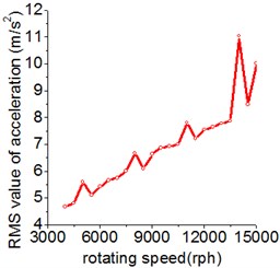
The RMS (root mean square) value of acceleration is an impactful tool to measure the vibration intensity. Fig. 6(a) displays the RMS value of gear i acceleration fluctuation against the rotating speed, the range of rotating speed is from 4000 to 15000 rph (revolutions per hour). With the increase of rotating speed, the RMS value of acceleration raise accordingly in general. The peaks correspond to the resonant response and the force acting on gear are amplified under dynamic condition, leading to the larger dynamic load and impact.
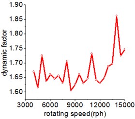
The mathematically calculated dynamic factor (DF) in this study is defined as the maximum meshing force to the static meshing force. The influence of rotating speed on dynamic factor is shown in Fig. 6(b) and the curve also includes several peaks corresponding to the critical speed just as Fig. 6(a) shown. That means the influence of rotating speed on the acceleration and dynamic factor can be applied to accurately predict the resonance speed of system.
Fig. 6The influence of rotating speed on the RMS value of acceleration and dynamic factor
a) RMS value of acceleration
b) Dynamic factor
3.3. Nonlinear dynamic of system
The dynamic trajectories offer a basic instruction to judge the behavior of system such as periodic, quasi-periodic and chaotic motion. In this paper, the unconditionally stable Newmark method is applied for time integration of motion equations. The primary mission is to investigate nonlinear dynamic of system by using effective tools. For example, time domain response, phase diagram, power spectrum, the maximum Lyapunov exponent and Poincare map.
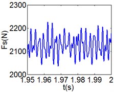
Fig. 7(4T motion, 4000 rph) Dynamic behavior of system in cylinder contact state
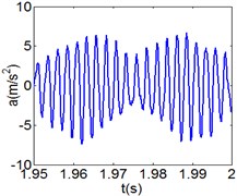
a) Acceleration
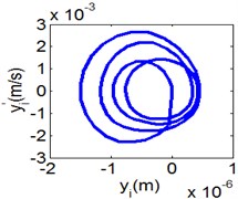
b) Phase diagram
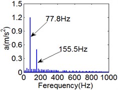
c) Power spectrum
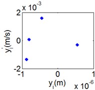
d) Poincare map
e) Shoulder iron contact force
f) Rubber contact force
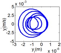
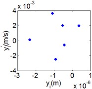
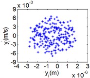
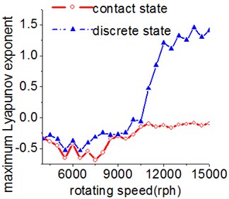
Time domain response and phase diagram make it easy for researchers to analyze the stability of motion and long-period motion. FFT method derived from the power spectrum is used to distinguish vibration frequency. The Lyapunov exponent of dynamic system characterizes the rate of separation and provides with available inspection for the presence of chaos. Negative maximum Lyapunov exponent represents periodic motion and positive maximum Lyapunov exponent denotes chaotic motion. Wolf method is used to calculate the maximum Lyapunov exponent due to the complexity of differential equations and the results of time series. Poincare map derived from Poincare section is a hypersurface in the state space. By definition, for nT-periodic motion, there are n discrete points on the map. A close curve on the map represents quasi-periodic motion and the irregularly distributed points indicate chaotic motion.
In this study, the simulation includes cylinder contact state (shoulder iron contact) and cylinder discrete state (shoulder iron separate). The dynamic behavior of system is tested by using rotating speed as a control parameter.
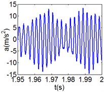
Fig. 8(6T motion, 11000 rph) Dynamic behavior of system in cylinder contact state
a) Acceleration
b) Phase diagram
c) Power spectrum
d) Poincare map
e) Shoulder iron contact force
f) Rubber contact force
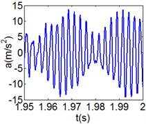
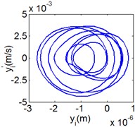
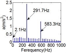
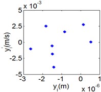
Fig. 9(8T motion, 15000 rph) Dynamic behavior of system in cylinder contact state
a) Acceleration
b) Phase diagram
c) Power spectrum
d) Poincare map
e) Shoulder iron contact force
f) Rubber contact force
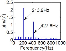
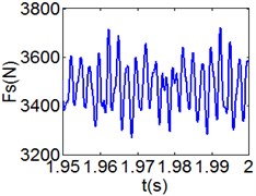
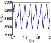
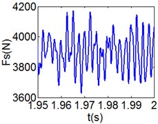
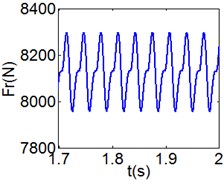
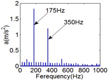
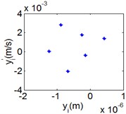
Fig. 7 shows the dynamic characteristics of system at 4000 rph. Fig. 7(a)-(d) display the acceleration of gear i, phase diagram, FFT and Poincare map. The 4T motions repeat themselves at every four mesh periods and have the small 1/4 order harmonic in the FFT spectrum. It is obvious that the first-order meshing frequency (77.8 Hz) and the second-order meshing frequency (155.5 Hz) dominate the power spectrum. A closed curve around four laps shows in the phase diagram and the Poincare map contains four points. The histories of both shoulder iron and rubber contact force are periodic but not 4T motions.
Fig. 8 and Fig. 9 show 6T and 8T motions and display 1/6 and 1/8 order harmonics, respectively. Fig. 7 to Fig. 9 have a similar trend and belong to sub-harmonic motion. On the other hand, with the increase of rotating speed, the acceleration, velocity, displacement, harmonic amplitude and shoulder iron contact force accordingly increase. In Fig. 9(c), the eccentric mass leading to the vibration frequency (2.1 Hz) becomes obvious at high speeds. The rubber contact force remains approximately unchanged which is crucial to ensure printing quality. The main reason for this phenomenon can be explained as shoulder iron avoids strong vibration.
Fig. 10(6T motion, 9000 rph) Dynamic behavior of system in cylinder discrete state
a) Acceleration
b) Phase diagram
c) Power spectrum
d) Poincare map
Fig. 11(Chaotic motion, 15000 rph) Dynamic behavior of system in cylinder discrete state
a) Acceleration
b) Phase diagram
c) Power spectrum
d) Poincare map
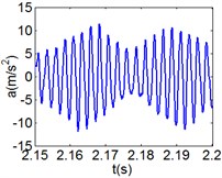
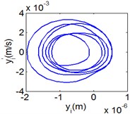
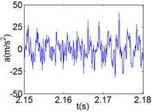
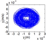
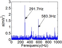
Fig. 10 and Fig. 11 respectively display 6T and chaotic motions when the system is in cylinder discrete state. Cylinders separated at high speeds results in chaotic motions and the phase diagram displays highly disordered. Comparing with the contact state, the acceleration, velocity and displacement have significantly increased. As Fig. 12 shown, the maximum Lyapunov exponents are calculated to judge chaotic motion. In contact state, the maximum Lyapunov exponents are negative in the range of rotating speed. In discrete state, the exponents are positive when rotating speed exceeds 11000 rph.
Fig. 12Maximum Lyapunov exponent
4. Conclusions
This study based on finite element method presents a numerical analysis of high speed offset press gear-cylinder-bearing. A dynamic model formed by gears, cylinders and bearings is proposed instead of lumped parameter model which is not accurate enough. Nonlinearity such as time-varying meshing stiffness, backlash, static transmission error and nonlinear Hertz contact are introduced to analyze the strong coupling among the transverse, torsional, axial and rotational motions. Lagrangian approach and the Newmark method are applied to obtain the critical speed and dynamic response. The critical speed obtained by mathematical model match well with ANSYS result. Bearing axial and radial stiffness significantly influence critical speed of system in a certain range. Peak values of acceleration and dynamic factor are proved to relate to nature frequencies. Nonlinear behavior of system is characterized by using the phase diagrams, power spectrum, the maximum Lyapunov exponent and Poincare map. It is obvious that there are periodic and chaotic motions in the dynamic trajectories, and the first and second-order meshing frequencies dominate power spectrum. This work provides a foundation for further improvement of the dynamic of gear system.
References
-
Özgüven H. Nevzat, Houser D. R. Mathematical models used in gear dynamics-a review. Journal of Sound and Vibration, Vol. 123, 1988, p. 383-411.
-
Vaishya M., Singh R. Analysis of periodically varying gear meshing system with coulomb friction using Floquet theory. Journal of Sound and Vibration, Vol. 243, 2001, p. 525-545.
-
Gao Oiang, Tanabe Makoto, Nishihara Kazue Contact-impact analysis of geared rotor systems. Journal of Sound and Vibration, Vol. 319, 2009, p. 463-475.
-
Fei Zhong Xiu, Tong Shui Guang, Wei Chao Investigation of the dynamic characteristics of a dual rotor system and its start-up simulation on finite element method. Journal of Zhejiang University – Science A, Vol. 14, 2013, p. 268-280.
-
Chang Jian C. W. The bifurcation and chaos of a gear pair system based on a strongly non-linear rotor-bearing system. Proceedings of the Institution of Mechanical Engineers, Part C: Journal of Mechanical Engineering Science, Vol. 224, 2010, p. 1891-1904.
-
Baguet S., Jacquenot G. Nonlinear couplings in a gear-shaft-bearing system. Mechanism and Machine Theory, Vol. 45, 2010, p. 1777-1796.
-
Lee An Sung, Ha Jin Woong, Hoon Dong Coupled lateral and torsional vibration characteristics of a speed speed increasing eared rotor-bearing system. Journal of Sound and Vibration, Vol. 263, 2003, p. 725-742.
-
Kang C. H., Hsu W. C., Lee E. K. Dynamic analysis of gear-rotor system with viscoelastic supports under residual shaft bow effect. Mechanism and Machine Theory, Vol. 46, 2011, p. 264-275.
-
Gunduz Aydin, Singh Rajendra Stiffness matrix formulation for double row angular contact ball bearings: analytical development and validation. Journal of Sound and Vibration, Vol. 332, 2013, p. 5898-5916.
-
Gao S. H., Meng G., Long X. H. Study of milling stability with Hertz contact stiffness of ball bearings. Archive of Applied Mechanics, Vol. 81, 2011, p. 1141-1151.
-
Maliha Rafiq, Dogruer Can U., Ozguven H. Nevzat Nonlinear dynamic modeling of gear-shaft-disk-bearing systems using finite elements and describing functions. Journal of Mechanical and Design, Vol. 126, 2004, p. 534-541.
-
Kubur M., Kahraman A., Zini D. M., Kienzle K. Dynamic analysis of a multi-shaft helical gear transmission by finite elements: model and experiment. Journal of Vibration and Acoustics, Vol. 126, 2004, p. 398-406.
-
Cai Y. Simulation on the rotational vibration of helical gears in consideration of the tooth separation phenomenon. Journal of Mechanical Design, Vol. 117, 1995, p. 460-469.
-
Cui Yahui, Liu Zhansheng, Wang Yongliang, Ye Jianhuai Nonlinear dynamic of a geared rotor system with nonlinear oil film force and nonlinear mesh force. Journal of Vibration and Acoustics, Vol. 134, 2012, p. 1-8.
-
Hernot X., Sartor M., Guillot J. Calculation of the stiffness matrix of angular contact ball bearings by using the analytical approach. Journal of Mechanical and Design, Vol. 122, 2000, p. 83-90.
-
Lin Chiwei, Lin Yangkuei, Chu Chihhsing Dynamic models and design of spindle-bearing systems of machine tools: a review. International Journal of Precision Engineering and Manufacturing, Vol. 14, 2013, p. 513-521.
-
Li Wenwei Multidisciplinary Synthesis Design Optimization of a High-Speed Multi-Color Offset Press. Southeast University, Nanjing, 2012, (in Chinese).
About this article
This research was supported by the National Natural Science Foundation of China (Grant No. 51205058) and the Transformation of Scientific and Technological Achievements Foundation of Jiangsu Province, People’s Republic of China (Grant No. BA2014110).
