Abstract
The paper introduces the principals and methods of universal multiscale modeling, and simply verifies them. It also derives the vibration equations of the bridge and the vehicles, and programs the universal program for analyzing two-axle vehicle-bridge coupled vibration via Ansys and Matlab software based on Newmark-β method. It proposes the universal method for analyzing vehicle-bridge coupled vibrations of long-span cable-stayed bridge based on multiscale model, and takes a single pylon cable-stayed bridge as an example to analyze and verify it.
1. Introduction
Long-span bridges are playing an increasingly important role in modern transportation. The long-span bridges such as river-crossing bridge and sea-crossing bridge etc. often have very complicated structures; therefore, and people often face the contradiction between the sophistication of local details and simplification of the entire structure when designing and analyzing the bridges [1-3]. Currently, in numerical analysis on the bridge structures, researchers often analyze the entire structural performance of the bridge by means of large scale beam element model, and analyze the local stress performance of the structure by means of modeling by comparatively sophisticated shell element or solid element. With many in-use bridges ceaselessly suffer the problems such as local damage and fatigue crack etc. during use, it gradually exposes various disadvantages in traditional modeling methods. As a result, multiscale model which can build models with different accuracies for different parts emerges quickly and develops well; this method can solve the problems of calculation accuracy and efficiency[4-7]. For long-span bridges, the vehicle-bridge vibration caused by passing vehicles cannot be ignored; such vibration will amplify the stresses at different parts of the bridges, the stresses of some parts may be much larger than the vehicle impact effect considered during designing, thus accelerating the damage and degradation of the bridges[8-12]. Therefore, the researchers need to analyze the dynamic characteristics of each part of the bridge under vehicle-bridge coupled vibration, thus guiding the designing work for the bridges.
Given the disadvantages existing in the uniform calculation method related to span or base frequency as adopted by vehicle impact coefficient in the specifications of bridges and culverts, this paper proposes the method for analyzing vehicle-bridge coupled vibrations of long-span cable-stayed bridge based on multiscale model in order to analyze the similarities and differences of vehicle impact effect at different parts of the bridges, with the problems of calculation accuracy and efficiency of long-span bridges taken into consideration. Firstly, the paper introduces the method and process of universal multiscale modeling method of long-span bridge, and verifies this modeling method with a simple example; then it introduces the analysis model of vehicle-bridge coupled vibration which is applicable to multiscale model; finally, it takes an actual single pylon cable-stayed bridge as an example to verify the method and process proposed in this paper.
2. Multiscale modeling method for long-span structure
2.1. Multiscale modeling method
When conducting multiscale modeling for a long-span bridge, comparatively sophisticated local models shall be built to carry out accurate analysis on the concerned parts of stress concentration and the parts where fatigue cracks are prone to occurring. For other parts of the bridge, in order to ensure the boundary conditions of the local models and the accuracy of the stress characteristics of the entire structure, the comparatively simplified model can be adopted to carry out analysis. When dividing the modeling scales of each part of the bridge, the vulnerable parts of the bridge structure can be determined in line with existing inspection reports on the bridge and the static and dynamic analysis results of the simplified model of the target bridge.
The effective connection between the interfaces of the simplified large scale model and sophisticated small scale model in the multiscale model is the key to ensuring the calculation accuracy of the multiscale model. The degrees of freedom of the models with different scales are often different due to their different element types; they are often connected by rigid beam or rigid zone in reality, but this method will generate stress concentration at the interface; therefore, it needs to minimize the redundant constraints of local small scale models as far as possible while avoid damaging the degrees of freedom of large scale models[13-15]. Adopting constraint equations can solve this problem better; the models with different scales can meet the plane cross-section assumption at the interface.
For a long-span bride structure, its sophisticated small scale models can be built by solid elements or shell elements, while its simplified large scale models can be built by beam elements; the two shall be connected via constraint equation at the interface, which can increase the calculation accuracy and efficiency of complicated structure models.
2.2. Verification on the connection of multiscale models
To verify the feasibility of multiscale model in bridge structure modelling and the accuracy of its calculation results, this paper takes the steel box girder which is commonly used in long-span bridges as an example, and cuts out a section of U-shaped ribbed stiffener and carrier plate to build a multiscale model. The thickness of the carrier plate of the steel box girder is 14 mm, the thickness of the U-shaped ribbed stiffener is 8 mm, the width of the carrier plate at this section is 0.6 m, the height of the ribbed stiffener is 0.28 m; take a section of 3 m between two diaphragm plates at longitudinal direction, simply support both ends for constraint. Build models via large universal finite element software ANSYS, build large scale beam element models with Beam189, and build small scale shell element model with Shell63, and built a multiscale model with blended elements. The three finite element models of the section are as shown in Fig. 1.
Fig. 1Finite element model of a section
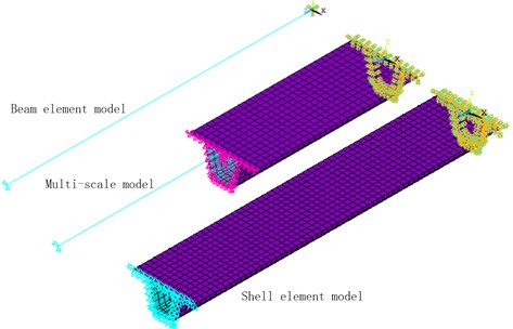
Modal analysis shall be carried out on the three models built; see Table 1 for the vibration frequencies of the first 6 stages of each model, and see Fig. 2 for the first-stage modality of the section of each model. According to the modal analysis results of each model, compared with beam element model, the natural vibration frequencies of the first 6 stages of multiscale model are closer to the natural vibration frequency of sophisticated shell element model, which indicates that this method has good calculation accuracy; meanwhile, it can increase the calculation efficiency to a great extent. For large structures with complicated structures, multiscale modeling method can better reflect its advantages in terms of both calculation accuracy and efficiency.
Table 1Modal analysis data of the section
Modality | Beam element model | Multiscale model | Shell element model |
Frequency (Hz) | Frequency (Hz) | Frequency (Hz) | |
1 | 110.10 | 111.01 | 110.95 |
2 | 129.42 | 132.85 | 131.03 |
3 | 194.04 | 195.25 | 196.34 |
4 | 225.60 | 223.63 | 219.39 |
5 | 232.15 | 230.35 | 225.54 |
6 | 246.02 | 242.21 | 235.47 |
Fig. 2The first-stage modality of the section

a) The first modal of the beam element model

b) The first modal of the multi-scale element model

c) The first modal of the shell element model
3. Methods for analyzing vehicle-bridge coupled vibration
3.1. Vehicle model
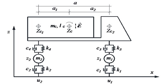
Vehicle models shall be two-axle vehicle models; the car body and the axle shall be simplified to be rigid body with certain mass, and they are connected by springs and damping systems. In view of the vertical displacement at the contact part between the two wheels and the bridge floor, the vertical displacements at both ends of the car body as well as the roll-angle and displacement of the barycenter, there are 8 degrees of freedom in total. See Fig. 3 for the vehicle model.
According to Alembert principle, the vibration equation of the simplified vehicle model shall be obtained as follows:
In the equation, M, C and K are the mass, damping and stiffness matrix of the vehicle respectively; P is the vector of the vehicle under the acting force of vehicle-bridge coupling; Z, ˙Z, ¨Z are the generalized displacement, speed and accelerated speed vector of the vehicle respectively.
Fig. 3Vehicle model
3.2. Pavement evenness model
Pavement evenness is an important reason that causes the vehicle-bridge vibration; its influence on the bridge vibration cannot be ignored. Its mechanism is that the rough pavement will cause redundant displacement, speed and accelerated speed at the vehicle-bridge contact surface, thus changing the acting forces between them. Generally, the pavement unevenness is deemed as to comply with Gauss random distribution [16-17]:
where, r(x) is the roadway profile, ϕ(∙) is the power spectral density function (m3/cycle/m), nk is wave number (cycle/m), Δn is frequency increment, θk is phase angle.
This paper simulates the pavement unevenness by means of trigonometric series superposition method, and divides the pavement unevenness into five grades of “excellent”, “good”, “general”, “bad” and “worse” [18]. Surface roughness is a function associated with the road surface roughness coefficient (ϕ(n0)), pavement roughness coefficient values are shown in Table 2.
Table 2Surface roughness coefficient values
No. | Grades | ϕ(n0) |
1 | Excellent | 2×10⁻⁶≤ϕ(n0)<8×10⁻⁶ |
2 | Good | 8×10⁻⁶≤ϕ(n0)<32×10-6 |
3 | General | 32×10-6≤ϕ(n0)< 128×10-6 |
4 | Bad | 128×10-6≤ϕ(n0)< 512×10-6 |
5 | Worse | 512×10-6≤ϕ(n0)<2048×10-6 |
3.3. Methods for analyzing vehicle-bridge coupled vibration
When analyzing vehicle-bridge coupled vibration, it needs to treat the bridge in a finite element discretization manner, thus obtaining the vibration equation under the system with several degrees of freedom:
In the equation, Mb, Cb and Kb are the mass, damping and stiffness matrix of the vehicle respectively; Pb is the vector of the vehicle under the acting force of vehicle-bridge coupling; Zb, ˙Zb, ¨Zb are the generalized displacement, speed and accelerated speed vector of the vehicle respectively.
After solving the dynamic equations of the bridge and the vehicle in line with the aforesaid method respectively, assume that the vehicle tyres and the pavement have never separated, the dynamic equations of the vehicle system and the bridge system can be coupled together by way of the compatibility condition between displacement and force at the contact point of the two [19]. This paper programs the universal program for analyzing two-axle vehicle-bridge coupled vibration via Ansys and Matlab software based on Newmark-β method.
4. Analysis on the vehicle-bridge coupled vibration of cable-stayed bridge based on multiscale model
4.1. Multiscale finite element model of cable-stayed bridge
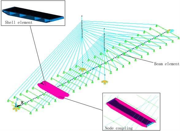
A single pylon cable-stayed bridge is taken as an example in this paper to build the multiscale finite element model of the bridge via ANSYS software in line with the aforesaid methods. The span of this bridge is 150 m+150 m, the girder is orthotropic steel bridge deck slab, the main pylon is gate-type pylon with uniform sections; the 24 pairs of inhaul cables are distributed symmetrically. Seen from existing survey results of the long-span bridge and the dynamic analysis on the model, the midspan part is the vulnerable position of the bridge structure. Therefore, this paper selects the middle part of the left span of the cable-stayed bridge for sophisticated small scale modeling, with the length of 3 intervals between diaphragm plates taken in the longitudinal direction; large scale finite element models are built by means of fish bone model for other parts; the finite element model of the bridge is as shown in Fig. 4. The small scale section of orthotropic steel bridge deck slab shall be built by Shell63 shell element, other girders and the main pylon shall be built by Beam188 element, the inhaul cable shall be built by Link8 element; the nodes shall be coupled on the interface between girder models of beam element and shell element by way of building constraint equation.
Fig. 4Multiscale finite element model of cable-stayed bridge
4.2. Analysis on vehicle-bridge coupled vibration
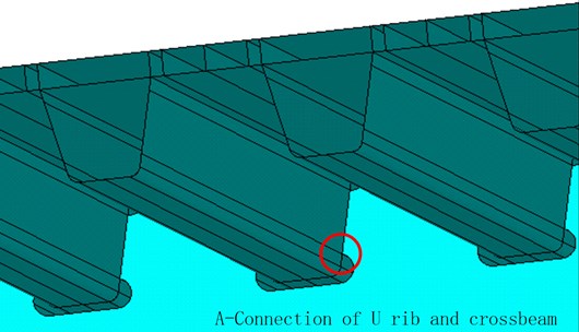
Under the vehicle load effect, the force conditions of different parts of the bridge made of the orthotropic steel bridge deck slab are different; some parts are prone to causing stress concentration. Therefore, even under one force application, the stress amplitude it bears shall be much larger than that borne by other parts in the same cross section, hence it will see fatigue failure earlier. To accurately learn the stress amplitudes of the vulnerable parts of the bridge, this paper, based on the statistics of existing inspection data of steel bridge cracks[20-21], selects the connection of longitudinal ribs and diaphragm plates from the shell element model of multiscale model to be the object area of this analysis, as shown in Fig. 5.
Fig. 5Connection between A-longitudinal rib and diaphragm plate
Analyzing this multiscale model of cable-stayed bridge by the aforesaid processes of vehicle-bridge coupled vibration can obtain stress time-history curve at each detailed fatigue part of the orthotropic steel bridge deck slab; it can be converted into equivalent stress amplitude by rain-flow counting method, thus guiding the anti-fatigue design for the bridge. This paper only illustrates A fatigue details. Point A is located on the cross-section, which is 75 m away from the main tower. To compare the influences of whether considering vehicle-bridge coupled vibration on stress history, the same bridge model is loaded by the aforesaid vehicle-bridge coupled vibration process and moving static load respectively. The stress histories at A under the two working conditions are as shown in Fig. 6 and Fig. 7. Pavement evenness is “general”, and the sample function of surface roughness at this moment is acquired based on the method for simulating pavement evenness. The 8 degrees of freedom vehicle model at fatigue standard travels across the bridge at the velocity of 80 km/h in the paper, the stress equation at A can be acquired. Fig. 6 shows the dynamic response curve at A in the structure when the vehicle passes the bridge at the premise of considering the effect of vehicle-bridge coupling. Fig. 7 shows the dynamic response curve at A in the structure under the condition that the vehicle is deemed as a moving static load to apply load on the structure without considering the effect of vehicle-bridge coupling. In Fig. 7, the vehicle load is placed on different positions of the bridge to apply the load, and the stress at A is acquired at this moment. Essentially, it’s a combination of many static force loads. Pavement unevenness is not involved in the static force loading. Therefore, the stress history curve is a smooth curve. The horizontal axis of Fig. 6 is the distance from the bridgehead of the vehicle load, and the vertical axis is the stress value of point A at this time. As can be seen form the figure, when the vehicle passes A, here the stress reaches a maximum value, this is consistent with actual situation. This sufficiently reflects the advantages of multiscale model; unlike large scale beam element model, it can accurately extract the stress history at different parts of the same cross section of the girder.
Fig. 6 and Fig. 7 are analyzed based on the same multiscale model. The effect of vehicle-bridge coupling is considered in the former, while the vehicles travelling on the bridge are deemed as moving static load to apply load in the latter. A comparison between them shows that the amplitude of the stress history curve is caused by vehicle-bridge coupled vibration instead of the multiscale model of the bridge. However, there is some difference in term of calculation accuracy based on different bridge models.
To compare the amplification effect of pavement evenness on the stresses at each part of the girder, the researchers carry out loading analysis on the vehicles on the pavement at five grades of “excellent”, “good”, “general”, “poor” and “very poor”, so as to obtain the impact coefficients under each road condition. See Fig. 8 for specific values.
Fig. 6The dynamic response at A in the structure at the premise of considering the effect of vehicle-bridge coupling
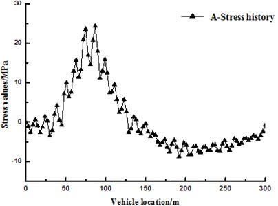
Fig. 7The dynamic response at A in the structure under static load
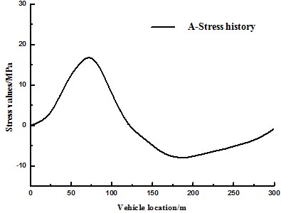
Fig. 8Influence of pavement evenness on impact coefficient
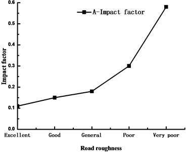
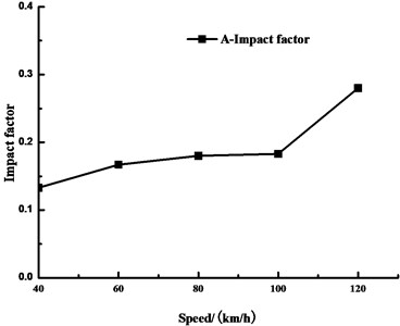
Fig. 9Influence of vehicle speed on impact coefficient
According to Fig. 8, when the pavement evenness is “excellent”, “good” and “general”, its influence on the impact coefficient of the stress at A is not so large; when the pavement evenness is “poor” and “very poor”, it will cause the travelling vehicles to suffer drastically continuous bumping, thus making the impact coefficient of the girder stress soar. Therefore, considering from the perspective of extending the service life of the bridge, the pavement needs to be overhauled and maintained frequently.
To compare the amplification effects of the travelling vehicles on the stresses at each part of the girder, make the loaded vehicles pass a bridge with “general” pavement evenness at the speed of 40 km/h, 60 km/h, 80 km/h, 100 km/h and 120 km/h respectively, obtain the impact coefficients of the stresses of the girder under different vehicle speeds. This paper only illustrates A; see Fig. 9 for the impact coefficients of the stresses of the girder at A under different vehicle speeds.
According to Fig. 9, in the speed range of 40 km/h-100 km/h, the vehicle speed variation doesn’t affect the amplification effect of the stress at A so obviously; that is to say, the impact coefficient at A is not sensitive to the vehicle speed in this range; however, when the vehicle speed increases to over 100 km/h, the impact coefficient at A increases to a great extent. Therefore, considering from the perspective of extending the service life of the bridge, the vehicle speed shall be limited in a reasonable range in actual operation of the bridge.
5. Conclusions
1) Multiscale modeling method can significantly increase the calculation efficiency under the premise of ensuring calculation accuracy, and has good universality; it can well apply to dynamic structural analysis of long-span bridges.
2) Unlike conventional large scale beam element model, analysis on the vehicle-bridge coupled vibrations of long-span cable-stayed bridge based on multiscale model can extract the stress histories at each part of the same cross-section in a sophisticated small scale model in line with the researchers’ different demands, thus increasing the accuracy of the analysis results. The method for analyzing the vehicle-bridge coupled vibrations of long-span cable-stayed bridge based on multiscale model is more applicable to anti-fatigue design for each part of the bridges.
3) Serious degradation of pavement evenness will significantly amplify the impact coefficients of each part of the bridge, thus reducing the service life of the bridge.
4) The vehicle speed in certain range doesn’t have an obvious influence on the impact coefficients of the bride; however, when the vehicle speed increases to over 100km/h, the impact coefficient of the bridge will increase to a great extent.
References
-
Li Zhaoxia, Sun Zhenghua, Guo Li, Chen Hongtian, Yu Yang Concurrent multi-scale modeling of structures and damage analyses. Journal of Southeast University, Vol. 37, Issue 2, 2007, p. 251-260, (in Chinese).
-
Li Z. X., Zhou T. Q., Chan T. H. T., Yu Y. Multi-scale numerical analysis on dynamic response and local damage in long-span bridges. Engineer Structures, Vol. 29, Issue 7, 2007, p. 1507-1524.
-
Chen Z., Yue X. Numerical homogenization of well singularities in the flow transport through heterogeneous porous media. Multiscale Model Simulation, Vol. 1, Issue 2, 2003, p. 260-303.
-
Efendiev Y., Ginting V., Hou T. Y., et al. Accurate multiscale finite element methods for two-phase flow simulations. Journal of Computational Physics, Vol. 220, Issue 1, 2006, p. 155-174.
-
Murat S., Jag Mohan H. Dynamic analysis of buildings for earthquake resistant design. Canadian Journal of Civil Engineering, Vol. 30, 2003, p. 338-359.
-
Oskayc Fish J. Multi-scale modeling of fatigue for ductile materials. International Journal of Multi-Scale Computational Engineering, Vol. 2, Issue 3, 2004, p. 1-30.
-
Ladeveze P. A Multiscale computational approach for contact problems. Computer Methods in Applied Mechanics and Engineering, Vol. 191, Issue 43, 2002, p. 4869-4891.
-
Xia H., Xu Y. L., Chan T. H. T. Dynamic interaction of long suspension bridges with running trains. Journal of Sound and Vibration, Vol. 237, Issue 2, 2000, p. 263-280.
-
Xu Y. L., Guo W. H. Dynamic analysis of coupled road vehicle and cable-stayed bridge systems under turbulent wind. Engineering Structures – Journal, Vol. 25, Issue 4, 2003, p. 473-486.
-
Xu Y. L., Xia H., Yan Q. S. Dynamic response of suspension bridge to high wind and running train. Journal of Bridge Engineering, Vol. 8, Issue 1, 2003, p. 46-55.
-
Alvandi A., Cremona C. Assessment of vibration-based damage identification techniques. Journal of Sound and Vibration, Vol. 292, 2006, p. 179-202.
-
Cawley P., Adams R. D. The location of defects in structures from measurements of natural frequencies. Journal of Strain Analysis, Vol. 4, Issue 2, 1979, p. 49-57.
-
Chu J., Efendiev Y., Ginting V., Hou T. Y. Flow based oversampling technique for multiscale finite element methods. Advances in Water Resources, Vol. 31, Issue 4, 2008, p. 599-608.
-
Chen J. R., Cui J. Z. A multicale finite element method for elliptic problems with oscillatory coeffcients. Mathematics of Comptation, Vol. 50, Issue 1, 2004, p. 1-13.
-
Thomas Y. H., Wu X. H. A multiscale finite element method for elliptic problems in composite materials and porous media. Journal of Computational Physics, Vol. 134, 1997, p. 169-189.
-
Honda H., Kajikawa Y., Kobori T. Spectra of road surface roughness on bridges. Journal of structural division ASCE, Vol. 108, Issue ST9, 1982, p. 1956-1966.
-
Zhang Wei, Cai C. S. Fatigue reliability assessment for existing bridges considering vehicle speed and road surface conditions. Journal of Bridge Engineering, Vol. 17, Issue 3, 2012, p. 443-453.
-
Au F. T. K., Chen Y. S., Cheung Y. K. Effects of random road surface roughness and long-term deflection of prestressed concrete girder and cable-stayed bridges on impact due to moving vehicles. Computers and Structures, Vol. 79, 2001, p. 853-853.
-
Huang D. Z. Dynamic analysis of steel curved box girder bridges. Journal of Bridge Engineering, Vol. 6, Issue 6, 2001, p. 506-513.
-
Wouter De Corte, Philippe Van Bogaert An evaluation of the use of fracture mechanics for the design of orthotropic decks. Key Engineering Materials, Vol. 348, 2007, p. 285-288.
-
Choi Dong Ho, Choi Hang Yong, Chung Sang Hwan, et al. Mixed-mode fatigue crack growth in orthotropic steel decks. Key Engineering Materials, Vol. 321, 2006, p. 733-738.
