Abstract
The falling weight deflectometer (FWD) is a non-destructive testing technology used to calculate the stiffness-related parameters of pavement structures and has been widely used in the pavement engineering field. Deflection basin testing data have an obviously affecting effect on the modulus backcalculation of an asphalt pavement. Identifying effective data of dynamic deflection basins is an important task to perform modulus backcalculation. The objective of this paper is to study the distribution features of dynamic deflection basins of cracked asphalt pavements using a three dimension dynamic finite element method. Based on the systematic analysis, the criteria used to filter effective data of FWD deflection basins were presented and verified with an in-situ case study. The study results demonstrated that the crack width of 0.2 mm was a critical value to determine the existence of contact behavior between vertical crack surfaces. The distribution characteristics of dynamic deflection basins showed a significant difference between intact and cracked pavements. The established criteria, involving surface deflection indicator and surface modulus indicator, were verified to be reasonable and viable for filtering the FWD testing data.
1. Introduction
With the recent developments and enhancements of the falling weight deflectometer (FWD) technology in the computations of stiffness related parameters of the pavement structures, non-destructive evaluation of physical properties and performance of pavements has taken up new capabilities. One of the critical technologies enabled by FWD is the estimation of in-situ elastic (Young’s) moduli of individual pavement layers by using backcalculations [1]. The FWD backcalculation is mathematically an inverse problem that could be solved with either a deterministic or a probabilistic approach. A review of the currently used backcalculation procedures indicates that the calculation is generally based on a homogeneous, continuous, and linear elastic multi-layer system. From these theoretical assumptions, a typical backcalculation method, such as the iterative method or the database searching method, can generally yield satisfactory back calculation results by fitting to the highest degree the theoretically estimated deflection basins with the measured deflection basins.
Obviously, the result of the backcalculation of an FWD test would depend on the physical condition of the pavement structure and therefore the occurrence of any type of pavement distresses may result in a difference in the result of the FWD backcalculation. Asphalt pavements are subject to environmental factors, such as cumulative traffic loading, material aging, and inclement weather conditions, which with time gradually deteriorate the existing asphalt pavements during service lives, resulting in various types of cracking distresses, such as transverse and longitudinal cracking, fatigue cracking, and block cracking. Under such circumstances, asphalt pavements manifest discontinuous and anisotropic characteristics [2]. If under FWD loading, the dynamic deflection basins of a cracked asphalt pavement would present discontinuous shapes due to the cracks occurring in the pavement structure, which might be significantly different from the distribution features of intact asphalt pavements [3]. Therefore, without considering the effect of distressed asphalt pavements on the surface deflection testing data, the backcalculation results derived based on the aforementioned assumption may have a large variability, and might not reflect the actual performance of the structural layers of an asphalt pavement.
Over the past two decades, several studies have been conducted to investigate the possible factors that may contribute to the differences in interpretation and backcalculation of FWD test results. For instance, Uddin et al. performed a significant number of dynamic analyses, taking into consideration the discontinuous asphalt pavements. The study results demonstrated that FWD deflection basins near the crack locations could not be used as the basis for the backcalculation of a moduli, since the deflection values close to the crack position tended to increase abruptly [4, 5]. Similarly, Lee et al. reported that the cracking distress of asphalt pavements had a significant influence on the backcalculation of moduli in the engineering practice [6]. Interestingly, Simon et al. and Mehta et al. demonstrated respectively the obvious variations in the pavement deflection basins before and after cutting seams to the pavement structures. The studies suggested that the deflection basin parameters, instead of structural layer moduli, could be used directly to evaluate the performance of distressed asphalt pavements [7, 8]. In addition, the results projected by National Cooperative Highway Research Program (NCHRP) Project 1-37A on the design of new and rehabilitated pavement structures indicates that the deflection basin parameters should be regarded as reasonable indicators to reflect the performance of distressed asphalt pavements, rather than backcalculated layer moduli [9].
In summary, the abovementioned research findings indicated that the measured pavement conditions should satisfy the theoretical assumptions set for the modulus backcalculation, when implementing the backcalculation to estimate the structural layer modulus. Otherwise, the backcalculated moduli might not truly constitute the capacity of evaluating the performance of asphalt pavements. Consequently, identifying effective data of dynamic deflection basins has become an important task to be done for the accurate performing of modulus backcalculation. Therefore, the main objective of this paper is to discuss the distribution features of dynamic deflection basins of asphalt pavements with crack distresses, and present the reasonable indicators and corresponding criteria to filter the testing data of FWD deflection basins. Finally, the paper also serves to validate the established criteria by conducting an in-situ case study.
2. Structural dynamics analysis basis
2.1. Dynamic equilibrium equation
The general dynamic equilibrium equation when the time element factored into the dynamic analysis can be presented in Eq. (1) [10]:
where, and are the acceleration vector and the velocity vector of system nodes, respectively. , , , and are the mass matrix, the damp matrix, the rigidity matrix, and the loading vector, respectively. The unit mass matrix is expressed as a consistent mass matrix to correspond with the direct integration Newmark- solution method. The damp matrix employs the Rayleigh form as shown in Eq. (2):
where, is the viscous damping parameter and is the structural damping parameter, which are the function of the critical damping ratio, and the inherent frequency, .
It is reasonable to assume to be 0.05 for general pavement structures. The inherent frequencies may be calculated by structural modal analysis. Considering that employing the first two principal modes to calculate the damping parameters can improve the accuracy of the results compared with the results obtained using only the first principal, the damping parameters for and can be indicated by Eq. (3):
2.2. Equation solution method
The traditional solution methods to dynamic equilibrium equations include mode superposition and direct integration. We assume that the solution up to time is known when the direct integration method is used, and the central difference method is used to determine the solution at time . The displacement, velocity, and acceleration are calculated using the Newton-Raphson iteration algorithm to satisfy the convergence condition. The basic solution equation in the analysis is indicated as Eq. (4):
where, and are the parameters constructed based upon known accuracy and stability. The function is stable when 0.5 and 0.25 ()2 based on the Newmark- algorithm. In the paper, and are assumed to be 0.505 and 0.2525, respectively, and the time step is limited to less than 1/50 of the basic period time [10].
3. Numerical analysis of dynamic response
3.1. Analysis model
A typical asphalt pavement is composed of an asphalt layer (AC), a cement treated base layer (BC), an unpaved subbase layer (sub-BC), and subgrade (SG). The material properties of various layers are presented in Table 1. The three-dimensional 10-node solid element was employed in the finite element method (FEM). The length of the element side was assumed to be 5 cm and the non-uniform mesh mapping method was adopted in consideration of the deployment of FWD testing points. To reduce the boundary effect, the optimized dimensions of the analysis model were assumed to be 5 m×5 m×4 m. The fixed displacement constrain was assigned to the bottom of the model, whereas the normal displacement constrain was applied to four side areas of the model. The interface condition between structure layers is considered fully bonded. The quarter of the mesh model and the quarter of the stress diagram for the analyzed asphalt pavement are illustrated in Fig. 1.
Table 1Material properties of asphalt pavements
Layer | Thickness (m) | Modulus (MPa) | Poisson ratio | Density (kg·m-3) | Damp ratio |
AC | 16 | 3 000 | 0.35 | 2 200 | 0.05 |
BC | 40 | 5 000 | 0.25 | 2 100 | |
Sub-BC | 15 | 250 | 0.35 | 1 900 | |
SG | – | 150 | 0.40 | 1 800 |
3.2. FWD loading model
The applied FWD force is an impulsive loading with a sinusoidal distribution feature, as listed in Eq. (5). The loading radius is 15 cm. The corresponding deflections were measured at a distance of 0, 20, 30, 60, 90, 120, 150, 180, and 210 cm from the load center. The layout scheme of nine sensors is presented in Table 2. The distance between the applied FWD load center and the crack edge was 16 cm. For measurements, the deflection sensors were placed across the transverse crack:
where, is loading peak value, 0.7 MPa. is FWD loading effect time, 0.03 s.
Table 2FWD sensor layout plan
Number | |||||||||
Distance | 0 | 20 | 30 | 60 | 90 | 120 | 150 | 180 | 210 |
Fig. 1FEM mesh model and stress diagram

a) Finite element mesh model
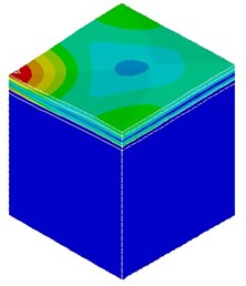
b) Stress diagram under FWD impulsive loading
3.3. Damping parameters solution
The modal analysis was used to determine the inherent frequencies, and the corresponding damping parameters, and , which are key parameters for conducting dynamic response analysis of asphalt pavements. The three kinds of algorithms including Block Lannzos (BL), Subspace (SS), and PowerDynamics (PD) were considered by the finite element method. It can be seen from Table 3, the three types of algorithms exhibit nearly same values of inherent frequencies and the damping parameters for and are 3.32 and 0.001, respectively.
Table 3Natural frequencies and damping coefficients of different methods
Mode | BL | SS | PD | ||||||
1 | 61.22 | 3.32 | 0.001 | 61.22 | 3.32 | 0.001 | 61.15 | 3.32 | 0.001 |
2 | 72.59 | 72.59 | 72.50 | ||||||
The effect of subentry damping parameters on surface dynamic deflection is illustrated in Fig. 2(a). The calculating conditions involve and concurrence, only , and only . The result indicates from Fig. 2(a) that the same time-history distribution of surface dynamic deflection is observed between and concurrence, and only . However, the damping parameter, , has little impact on the time-history distribution of surface dynamic deflection. Therefore, it may be neglected for the dynamic analysis of asphalt pavement structures.
The effect of layer material damping feature on surface dynamic deflection is presented in Fig. 2(b). The result demonstrates that the SG damping behavior has a salient effect on surface dynamic deflection when compared with other structural layers. The damping behaviors of structural layers including AC, BC, and Sub-BC have almost no effect on surface dynamic deflection, which is similar to the non-damp condition of the studied asphalt pavement. It indicates that the damping parameter, , can be determined solely upon the subgrade condition and has nothing to do with the other structural layers. It further implies that various surface crack conditions of asphalt pavements do not affect the damping parameter calculation value. The finding provides a very important support to conduct the dynamic response analysis of cracked asphalt pavements.
Fig. 2Effect of damping parameters on surface dynamic deflection
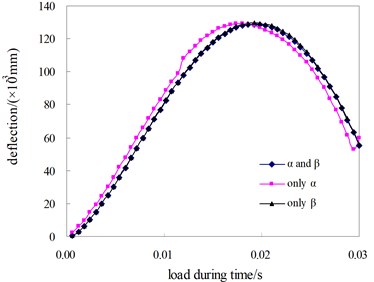
a) Effect of subentry damping parameters
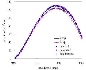
b) Effect of lay material damping parameters
4. Contact analysis of vertical crack surfaces
4.1. Overview of crack distresses
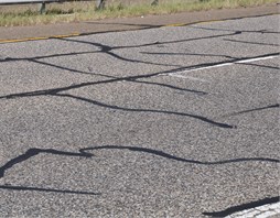
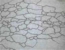
According to extensive field surveys, the crack distress is a common problem of structural damages for asphalt pavements. The typical crack distresses include transverse/longitudinal cracks, block cracks and alligator cracks. The illustration of the different cracks distresses is shown in Fig. 3. As shown from Fig. 3, a longitudinal crack is typically parallel to the pavement centerline, while transverse cracks extend across the centerline. Such longitudinal and transverse cracks are caused under several conditions, including shrinkage of asphalt surface due to low temperatures, asphalt hardening, or due to reflective cracks caused by cracks beneath the asphalt surface, which accounts for almost 80 % of all the distresses. On the other hand, the block or alligator crack is a series of interconnecting cracks caused by the fatigue failure of the cement treated base under repeated traffic loading. These block cracks propagate to the surface initially as one or more longitudinal parallel cracks.
Fig. 3Different crack distresses illustration
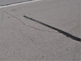
a) Transverse/longitudinal cracks
b) Block cracks
c) Alligator cracks
To introduce the discontinuity condition into the simulation system, interface elements were used to simulate the vertical cracking contact condition. In general, the vertical contact condition between cracks is governed by the maximum allowable shear stress and friction coefficient [11]. In the study, a typical distressed asphalt pavement with a transversal crack cutting through from the asphalt layer to the base layer was chosen to analyze the effect of the crack width and the friction coefficient on surface deflection with the three-dimensional dynamic finite element models.
4.2. Results and discussion
The implementation plan of the contact analysis, including crack width and friction coefficient, is described in Table 4. As illustrated in Fig. 4, pavements with more than 0.2 mm crack width, such as A1, A2, B1, and B2, yield the same surface deflections irrespective of values of friction coefficients. This could be attributed to the fact that the gaps remain a separate condition in that the deformations between the crack surfaces are smaller than 0.2 mm. On the other hand, when the crack width is less than 0.2 mm, the deflections gradually decrease with the decreasing of the crack width and with the increasing of the friction coefficient. Similar conclusions are reported by Lee et al. and Uddin et al. [5, 6]. The field surveys indicate that the typical gap of various crack distresses is often more than 1 mm, therefore, it is feasible to ignore the vertical contact conditions of crack interface surfaces.
Fig. 4Deflections under different contact parameters
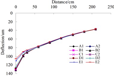
Table 4Plan of analysis
Number | Crack width (mm) | Friction coefficient |
A1 | 1 | 0.5 |
A2 | 1 | 1 |
B1 | 0.5 | 0.5 |
B2 | 0.5 | 1 |
C1 | 0.2 | 0.5 |
C2 | 0.2 | 1 |
D1 | 0.05 | 0.5 |
D2 | 0.05 | 1 |
E1 | 0.02 | 0.5 |
E2 | 0.02 | 1 |
5. Influence of crack distresses on dynamic deflections
5.1. Transverse single crack
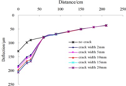
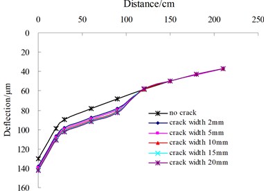
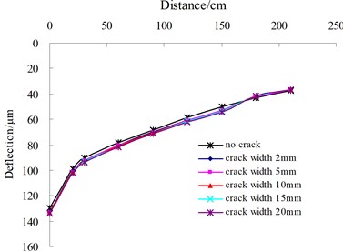
The influence of transverse single crack on surface dynamic deflection are analyzed and the analysis variables involve the distance from the center of FWD loading to crack edge, which is defined as , and crack width. As illustrated in Fig. 5, the influence of crack width under the condition of transverse single crack on surface deflections present the different results with the change of the . When is located between 0 cm and 150 cm, the shapes of deflection basins change sharply and appear discontinuous distribution features. However, with the increase of the , the shape of the surface deflection basin becomes more and more smooth, which is similar with the deflection distribution of the intact pavement. Under the condition of less than 150 cm, the surface deflection points near to FWD load edge prominently increases with the increasing of the crack width. In contrast, the values of other deflection points remain unchanged.
Fig. 5Influence of transverse single crack on surface deflection
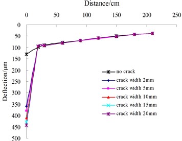
a) 16 cm
b) 45 cm
c) 110 cm
d)165 cm
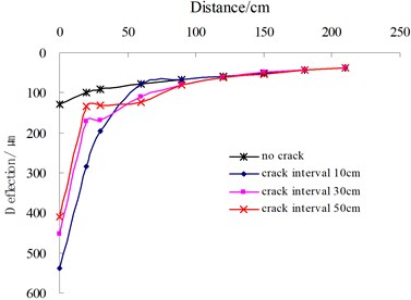
Fig. 6Influence of transverse multiple cracks on deflection
5.2. Transverse multiple cracks
The distance from the center sensor of the applied FWD loading to the first crack edge was kept at 16 cm. The other deflection sensors were placed across the first crack. The crack width was assumed to be 5 mm. Fig. 6 depicts the influence of the transverse crack interval on surface deflections. The results indicate that the crack interval is a prime determinant to affect the distribution of surface deflection basins of asphalt pavements. With the decreasing of the crack interval, the distribution shape becomes gradually smooth.
5.3. Longitudinal single crack
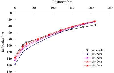
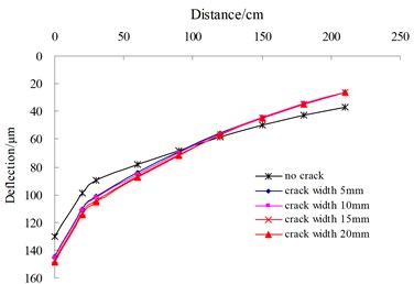
All deflection sensors were placed in parallel, along with the longitudinal crack edge. The two variables were analyzed involving the distance from FWD loading center to crack edge, which is defined as , and crack width. Fig. 7(a) illustrates the influence of on surface deflections when the crack width is 10 mm. The results indicate that the center deflections continuously decrease and tend to the deflection value of the intact pavement with the increasing of the . Fig. 7(b) shows the influence of the crack width on surface deflections when is 35 cm. It could be seen that the surface deflection distribution are similar each other under the condition of different crack width, however, they are clearly different from that of the intact pavement.
Fig. 7Influence of the distance and crack width on deflection
a) Distance
b) Crack width
5.4. Block cracks
In reality, the shape of block cracks is quite irregular and cannot be described completely. Therefore, a kind of “idealized” block crack model was established by multiple cross transverse and longitudinal cracks to magnify the discontinuity effect that would occur in the field. The FWD loading center was located in the middle of block cracks, while the other sensors were placed across the cracks. Fig. 8 shows the influence of block cracks on surface deflections when the crack width is 5 mm. The results indicate that the distribution characteristics of dynamic deflection basins showed a significant difference between intact pavements and cracked pavements with the increasing of crack interval.
Fig. 8Influence of block cracks on deflection
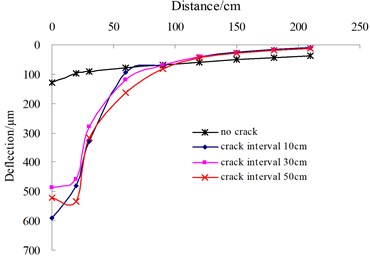
Fig. 9Surface modulus versus distance
6. Indicators for filtering deflection data
6.1. Direct deflection indicator
Cracking distresses often reduce the stiffness of the AC layer, as well as cause discontinuities in pavements. When severe discontinuities exist, the FWD deflection basins may show unusual shapes. As evidenced from the abovementioned results, the outer sensor deflection is greater than the inner sensor deflection, when severe discontinuities exist in upper layers. Hence, the direct deflection indicator as shown in Eq. (6), can be utilized to identify asphalt pavements distresses, such as transverse multiple cracks and block cracks:
6.2. Surface modulus indicator
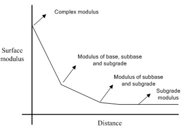
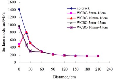
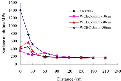
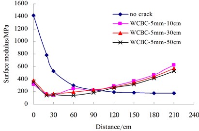
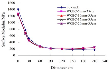
Generally, the surface modulus () of asphalt pavement gradually decreases close to the stable subgrade modulus. Fig. 9 illustrates the typical tendency of the surface modulus. According to Boussinesq’s theory, the surface modulus can be calculated from the deflection measured at a given distance as shown in Eq. (7):
where, is the loading pressure, is the radius of loading area, is the radial distance of the th sensor, is the Poisson’s ration and is the deflection of position. For multilayer pavement asphalts, the radial distances of 20 cm, 30 cm, and 60 cm were adjusted to 18 cm, 29 cm, and 59 cm, respectively, as suggested by Johnson and Baus [12].
Fig. 10Surface modulus distribution
a) Transverse single crack
b) Longitudinal single crack
c) Transverse multiple cracks
d) Block cracks
The surface moduli of cracked asphalt pavements were calculated and plotted as shown in Fig. 10. For transverse or longitudinal single crack, the symbol, WCBC-10 mm-16 cm, indicates that the crack occurs in AC layer and BC layer, with crack width of 10 mm and distance of 16 cm from FWD loading center to crack edge. For transverse multiple cracks or block cracks, the symbol, WCBC-5 mm-50 cm, indicates that the existing crack occurs in AC layer and BC layer, with crack width of 5 mm and crack interval of 50 cm. The results demonstrate that the distribution of surface modulus are dramatically different between intact pavements and cracked pavements. Therefore, for cracked asphalt pavements the surface modulus indicator is proposed to identify such unusual cases as shown in Eq. (8):
Fig. 11Filtering indicators validation of cracked asphalt pavements
a) Deflection distribution
b) Surface modulus distribution
Fig. 12Crack distresses survey in-situ
a) Transverse single crack
b) Core samples at corresponding transverse crack
c) Fatigue cracks of pavement surface
d) Cracks of corresponding base lay
7. Field validation analyses
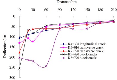
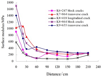
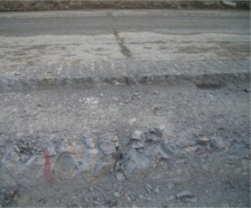
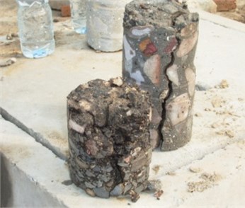
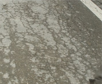
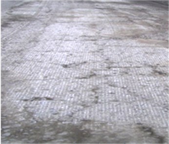
To validate the established indicators for filtering deflection data of cracked asphalt pavements, the FWD trials were implemented in Huning expressway of China, which involves longitudinal single crack, transverse single crack, block cracks and fatigue cracks. The distribution features of the deflection and surface modulus are illustrated in Fig. 11. The field surveys indicate that the testing points exhibit different types of crack damages, as shown in Fig. 12. The results clearly demonstrate that the indicators established in this study for filtering deflection basin data for cracked asphalt pavement are viable and reasonable.
8. Conclusions
This paper presents the research progress in developing workable criteria for filtering the effective deflection basin data utilized to implement modulus backcalculation of asphalt pavements. The main findings are summarized as the following descriptions. The crack width of 0.2 mm is a critical value to determine whether there is contact behavior between vertical crack contact surfaces. Because the gap of various crack distresses is often more than 1 mm, it is feasible to ignore the contact behavior of vertical crack surfaces when implementing the mechanical analysis of cracked asphalt pavements. The distribution characteristics of dynamic deflection display a dramatic difference between intact and cracked asphalt pavements. Field surveys demonstrated that the criteria involving direct deflection indicator and surface modulus indicator are viable to filter the testing date of FWD deflection basins.
References
-
American Association of State Highway and Transportation Officials. Guide for Design of Pavement Structures. Fourth Edition, Washington, D.C., 2011.
-
Lee Y. C. Condition Assessment of Flexible Pavements Using FWD Deflection. North Carolina State University, North Carolina, 1997.
-
Ziari H., Khabiri M. M. Interface condition influence on prediction of flexible pavement life. Journal of Civil Engineering and Management, Vol. 8, Issue 1, 2007, p. 71-76.
-
Uddin W., Zhang D., Fereandez F. Finite element simulation of pavement discontinuities and dynamic load response. Journal of the Transportation Research Board, Vol. 1448, 1994, p. 100-106.
-
Uddin W., Hackett R. M., Joseph A., et al. Three-dimensional finite element analysis of jointed concrete pavement with discontinuous. Journal of the Transportation Research Board, Vol. 1482, 1995, p. 26-32.
-
Lee Y. C., Kim R., Ranjithan S. R. A dynamic analysis-based approach to determine flexible pavement layer moduli using deflection basin parameters. Journal of the Transportation Research Board, Vol. 1639, 1998, p. 36-42.
-
Grenier S., Konrad J. M. Evaluation of the influence of asphalt concrete pavement discontinuities on falling weight deflectometer measurements. Proceedings of the 6th International Conference on the Bearing Capacity of Roads and Airfields, Rotterdam, 2002, p. 617-627.
-
Mehta Y., Roque R. Evaluation of FWD data for determination of layer moduli of pavements. Journal of Materials in Civil Engineering, Vol. 15, Issue 1, 2003, p. 186-195.
-
Guide for Mechanistic-Empirical Design of New and Rehabilitated Pavement Structures. Project 1-37A, Transportation Research Board, National Research Council, Washington, D.C., 2004.
-
Ray W. C., Joseph P. Dynamics of Structure. Second Edition, Computers and Structures Inc., Berkeley, California, 1995.
-
Xu B. Assessing Pavement Layer Condition Using FWD Deflection Data. North Carolina State of University, North Carolina, 2000.
-
Johnson A. M., Baus R. L. Simple calculation of subgrade modulus from Nondestructive pavement deflection testing. Journal of the Transportation Research Board, Vol. 1406, 2005, p. 432-441.
About this article
The authors appreciate the following funding supports including the Natural Science Foundation (LQ14E080006) and the Science and Technology (2013C33023) of Zhejiang, China.
