Abstract
A million kilowatt horizontal residual heat removal pump is an essential part of the first loop residual heat removal system in nuclear power plants; it is the second most significant piece of nuclear power equipment. The residual heat removal pump of a nuclear power plant is examined by using a multiseismic spectrum, multiinput direction method to analyze its dynamic characteristics and responses. The aim of this analysis was to determine the seismic responses and possible actions to reduce damage to the integral structure. The favorable and unfavorable spectra are investigated as well. The research focuses on avoiding the damaging effects caused by earthquakes. The maximum value of seismic effect and the corresponding seismic input direction are determined, laying a speculative foundation for structural design and installation. Utilizing a response spectrum method, the antiseismic performance of a pump at SSE seismic load has been analyzed according to an algorithm using the square root of the sum of the squares. The result shows that the deformation of the impeller surface fitted with a wear ring decreases along the direction of flow in different input directions of the seismic spectrum. The largest deformation occurs at an angle of approximately 135 degrees; thus, antiseismic analysis should be conducted at this input angle to conservatively evaluate the antiseismic performance, and the installation angle designed for frequent earthquakes should avoid 135 degrees to decrease the deformation caused by the seismic force. Calculation results prove that the clearance between the rotor and the stator of the horizontal residual heat removal pump shows satisfactory seismic response performance that fulfills the requirements for antiseismic design according to the RCC-M standard; this may reduce seismic damage and avoid environmental disasters.
1. Introduction
According to statistical data from the American Preliminary Determinations of Epicenter, the last ten years have seen 1062 earthquakes with a moment magnitude of 6.0-7.0, 161 earthquakes with a magnitude of 7.0–8.0, and 19 earthquakes with a magnitude of 8.0-9.0 around the world. On March 14, 2011, Japan’s Fukushima nuclear power plant faced the risk of explosion because of inadequate seismic capacity design. Similar troubles were caused by a 2010 earthquake with a magnitude of 6.5 in Iran and a 2008 earthquake in Sichaun, China. As earthquakes occur frequently, people are becoming increasingly aware of their huge danger, and the destruction of machines by earthquakes has caused engineers to raise the requirements during research on shock tolerance and seismic response analysis methods for nuclear power plants [1, 2].
Nuclear power is a clean energy. Growing concern over global warming and climate change has led governments and communities to increase nuclear power development to meet electricity demands and environment requirements, optimize the energy structure, and ensure energy security [3-5]. Nuclear power plants have a residual heat removal pump within their containment shell. The residual heat removal pump is a key part in the first loop of the residual heat removal system (RRA) in nuclear power plants and is considered to be level 2 among the most important nuclear power equipment [6, 7]. The pump brings out residual heat after normal or accidental shutdown of the reactor to maintain the safety of the nuclear power plant and must meet the level I anti-seismic requirement. It has three operation conditions; the fluid flow has a large influence on the pump structure.
The direction of seismic input is an indispensable parameter in antiseismic analysis, because the value of the seismic effect inside a structure changes according to the directions of seismic input. The seismic force is essentially a series of ground input accelerations. Consequently, the seismic input direction must be taken into consideration when calculating structural seismic response, owing to the vector properties of acceleration. The dynamic response of a pump structure is different owing to different seismic input directions, leading to different seismic effects in different components of the integral structure. The favorable and unfavorable spectra can be investigated to evaluate the antiseismic performance and to direct the installation of the residual heat removal pump according to the regional seismic situations: different Safe Shutdown Earthquake (SSE) seismic spectrum input directions have different influences on the structure.
Numerical methods for solving the seismic response spectrum have been developed for seismic response analysis over the last decade, and most of the research works have focused on analyzing the deformation or stress under seismic load. Suarez [8] studied the seismic response characteristics of a rotating machine under simulated base excitations through different principles; these characteristics included speed-dependent gyroscopic terms, base rotation-dependent parametric terms, and several forcing function terms. Karasudhi [9] adopted infinite elements in the far field and finite elements in the near field to analyze the seismic response by imposing three concentrated orthogonal forces. Dimentberg [10] studied transverse random vibrations below the instability threshold by considering both external and internal damping. Zhou [11] analyzed the dynamic characteristics of a coolant pump in a nuclear plant by using the response spectrum method and found the natural frequencies of vibration, modes of vibration, and possible steps to decrease the overall damage to the system. Yang [12] analyzed the equivalent static characteristics of a canned motor pump by applying a finite element model (FEM). Zhou [13] analyzed the stress of a reactor coolant pump under different conditions and used the seismic response method with multi-spectrum input directions, the model is a vertical pump, but the research on a horizontal pump is little. Seismic response analysis is part of civil engineering, but there has been little research done on such analysis for rotating machines. The value of seismic effect varies with the seismic input directions because the projections on vibration modes change with the directions of seismic input. It is difficult to use a combination of vibration modes to determine unfavorable seismic input directions according to the value of the seismic effect. Each value of the seismic effect may not achieve the maximum value of the same seismic input direction, so the seismic response should be analyzed at each seismic input direction. The current seismic response methods are unable to directly predict the favorable and unfavorable spectra.
In summary, there is little literature on seismic response analysis with a focus on the deformation caused by the seismic force in different seismic spectrum input directions to evaluate the anti-seismic performance of residual heat removal pumps. In this study, a numerical analysis of the value of the seismic effects of different seismic spectrum directions is carried out by using the method of response spectrum analysis. The deformation of the impeller surface fitted with a wear ring, the pressure and suction sides of the blade, and the surface of the impeller outlet are quantitatively analyzed according to the seismic loads of different seismic input directions. Some experimental data were also collected to verify the accuracy of the simulation.
2. Structure description
The residual heat removal pump is installed in the containment shell of a nuclear power plant to maintain the pressure characteristics by completing the water-filling and high-pressure water-injection [14-15]. The residual heat removal pump and its components are required to maintain the pressure characteristics and finish water-filling and safe water injection with sealing and high pressure. The seismic response performance at the SSE seismic load is analyzed according to the square root of the sum of the squares (SRSS) algorithm by, which simultaneously considers the actions of gravity, the normal operation load, the maximum piping load under accident conditions, and the SSE load.
A horizontal centrifugal residual heat removal pump with a diffuser was selected as the simulation model. An overview of the pump structure is shown in Fig. 1. The diffuser was designed to produce a more uniform flow, and the annular volute afforded greater structural stability of the pump. The bearing box functioned as a heat shield that isolated the motor from the heat transferred from the fluid in the pump chamber. The material properties of the residual heat removal pump are given in Table 1.
Fig. 1Schematic of the pump structure
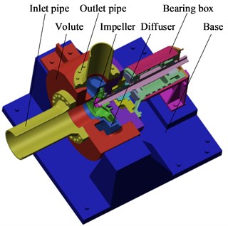
Table 1Material properties
Component | Stator | Rotor | Base and bearing box |
Material | Z2CND13-04 | Z2CN18-10 | 20MN5M |
Density (kg/m-3) | 7690.65 | 7270.06 | 7991.96 |
Young’s modulus (Pa) | 206-e9 | 197-e9 | 204-e9 |
Poisson’s ratio | 0.32 | 0.3 | 0.3 |
3. Seismic response analysis under extreme conditions
3.1. Seismic excitation parameters and characteristics
Integrity and operability under seismic load according to the Règles de Conception et de Construction des Matériels Mècaniques des Ilots Nucléaires PWR or, in English, “Design and Construction Rules for the Mechanical Components of PWR Nuclear Islands” (RCC-M 2000) standard [16] are assessed by determining whether the deformation of the rotor surface is larger than the clearance between the rotor and the stator. The SSE seismic load is applied to the bottom surface of the base, which is attached to the ground. Safe Shutdown Earthquake is a jargon of American Nuclear Control Association, specifically referring to the earthquake with maximum ground shock which could still make sure the nuclear reactor safely shutdown bringing no danger to the public. It is the maximum possible earthquake confirmed by analyzing the geological conditions, seismic conditions and the material properties under the ground of the area where the nuclear power plant located. And in this case, the important structure, system and equipment for safety concern should also maintain the following functions: 1) the capability to maintain the integrity of the pressure boundary of the reactor coolant and 2) the capability to shut down the reactor and keep it in the state of safe shutdown. To estimate the maximum ground acceleration of safe shutdown earthquake (SSE) for nuclear power plant site is a most important work of the structural engineer, seismologist and geologist. The response spectrum method of modal decomposition is used to obtain the strength of the seismic response for each structural vibration mode; the intensity is regarded as the maximum projected value of the seismic effect on the vibration mode. Next, the value of the seismic force is obtained after combining these values of seismic response. Before using this method, the input direction of the seismic force should be assumed. The seismic effect varies with the spectrum input direction, because the seismic projection on the vibration mode changes with the directions of seismic input. In addition, the residual heat removal pump is placed on the floor of the reactor building and the spectra of three orthogonal accelerations are obtained after the SSE response spectrum is discretized. The maximum seismic response is computed based on the seismic input acceleration. The square root of the sum of the squares (SRSS) is used, which is based on probability, statistics of a random event, and complete independence between participating dates without a coupling relationship. The accelerations of the horizontal and vertical walls as presented in Fig. 2 were imposed on the integral structure. The acceleration spectrum is obtained from the response spectrum of the floor with the residual heat removal pump. Response spectrum analysis and time-history analysis both reflect the influence of seismic dynamic characteristics and structural dynamic characteristics on structural seismic response. But the calculation of the response spectrum analysis is with higher convenience and less calculation, which can calculate the maximum value of the structural seismic response efficiently. So this paper analyzed the seismic response of residual heat removal pump in nuclear power plant by response spectrum analysis method. The accelerations of the horizontal and vertical walls can be considered to be independent. The SRSS was used to analyze the maximum deformation in the section perpendicular to the shaft. As shown in Fig. 5(a), the clearance between the impeller and the diffuser should be guaranteed to ensure that there is no rub or disturbance between the rotor and the stator as required by RCC-M 2000.
Fig. 2a) Acceleration spectrum of horizontal floor, b) Acceleration spectrum of vertical floor
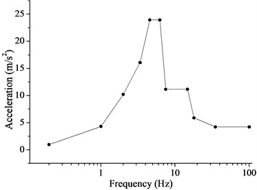
a)
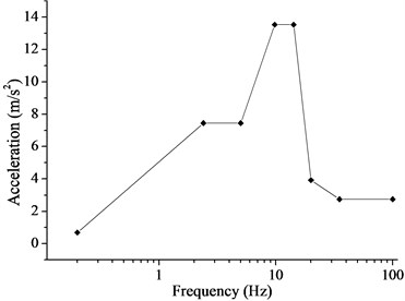
b)
The theory of seismic response spectrum takes account of the dynamic relations between the structural dynamic characteristics and the seismic dynamic characteristics, and remains the original static theoretical format. The maximum seismic base shear of the structure is as follows:
where the is the ratio of the acceleration response spectrum and the maximum acceleration of ground motion , that is , which means the magnification of acceleration of the structure.
3.2. Computational setup
The solid model of residual heat removal pump is created in Pro/Engineer and the CAD model of the complete structure is imported into ANSYS Workbench 14.5 preprocessing environment to create the finite element model required in the analyses.
Finite element model required in FE analysis is created by discretizing the geometric model shown in Fig. 1 into smaller and simpler elements. The discretization is performed in ANSYS environment. The three-dimensional solid model assembly of residual heat removal pump is transferred to ANSYS Workbench by direct interface. ANSYS Workbench automatically recognizes the contact conditions for corresponding contact surfaces. Completely bonded contact type is chosen as contact condition for contact surface.
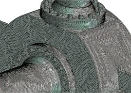
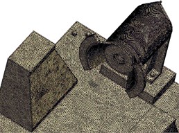
Complete model consists of around 1891637 elements and 3127918 nodes. Fine mesh is applied to the implant models. The finite element model of the stator, rotor, and base and bearing box are shown in Fig. 3.
Fig. 3a) Finite element model of rotor, b) Finite element model of stator, c) Finite element model of base and bearing box
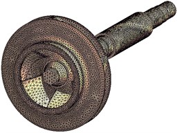
a)
b)
c)
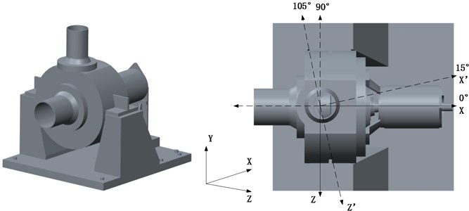
A multiseismic spectrum, multiinput direction method is applied to analyze the dynamic characteristics and seismic response. The seismic excitation direction of the earthquake spectrum is shown in Fig. 4. The seismic spectra in the horizontal direction () and vertical direction () are input every 15 degrees and the total deformation response is obtained by the SRSS method. The vertical accelerations of seismic force have two directions, but only the downward vertical acceleration is computed for the consideration of conservation, because the self-weight is vertically propelled downward. The surface between the stationary component and the rotating component consists of the impeller surface, fitted with a wear ring, and the outlet surface of the impeller; therefore, the influence of their deformation is crucial to the use of the residual heat removal pump. The nuclear pump will leak if the deformation of the impeller surface fitted with a wear ring and the outlet surface of the impeller are larger than the nuclear RCC-M 2000 standard. Some monitoring points are set on the impeller surface fitted with a wear ring and the outlet surface of the impeller to study the deformation responses.
Fig. 4Seismic excitation direction of the earthquake spectrum
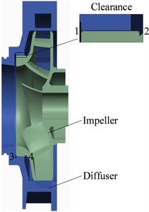
The essence of antiseismic analysis is to evaluate the operability of the pump structure by judging the existence of rubs or disturbances between the rotor and stator components. If there are rubs and disturbances, the pump structure will be damaged and at risk for accidents such as nuclear leakage. Therefore, the deformation of the rotor and stator components is calculated in ANSYS Workbench 14.5. The monitoring points on the impeller surface fitted with a wear ring, the pressure and suction sides of the blade, and the outlet surface of the impeller are shown in Fig. 5. Points 1-4 are distributed on the impeller surface fitted with a wear ring, points 5-12 are set every 45 degrees on the surfaces of the shroud and the hub, and points 13-16 are set on the pressure and suction sides of the blade.
Fig. 5a) Monitoring points on the surface corresponding with the wear ring, b) monitoring points on the outlet surface of the impeller, c) monitoring points on the pressure and suction sides of the impeller
a)
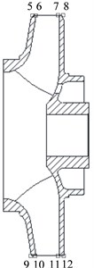
b)
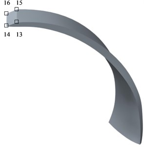
c)
The deformation factor is defined as:
where is the deformation factor, is the deformation at each seismic input direction, and is the mean deformation based on all calculated deformation values.
4. Results and discussion
A residual heat removal pump is a type of special centrifugal pump with antiseismic requirements. Therefore, decreasing the seismic effects on the residual heat removal pump is an indispensable consideration when designing residual heat removal pumps. In this study, a three-dimensional (3D) finite-element (FE) model pump is used to study the mechanical properties and dynamic analysis of the pump, instead of the traditional method using a mechanical model. FE prediction and analysis, concentrating on the seismic response to multiinput directions, are conducted to evaluate the antiseismic performance in a residual heat removal pump.
4.1. Deformation of impeller surface fitted with wear ring
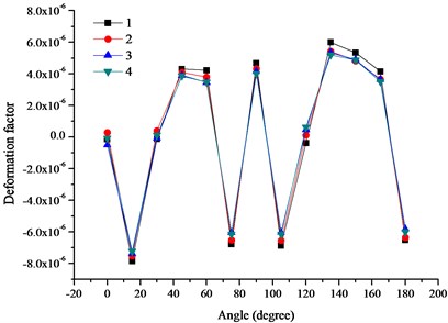
Fig. 6 shows the deformation response to different input directions under SSE seismic load. The response value varies in different directions, because the vibration frequency changes when the input direction changes. Although the vibration frequency is the same in different input directions, the deformation response is different because the pump structure is asymmetrical. As also shown in Fig. 6, the deformation of the impeller surface fitted with a wear ring in the section perpendicular to the shaft shows multiple extreme values. Furthermore, point 1 has the largest deformation, which is larger than that of point 2. This indicates that the deformation decreases along the direction of flow in different seismic spectrum input directions. In addition, the deformation varies greatly with the direction of the seismic spectrum input; therefore, the seismic response characteristic of the horizontal residual heat removal pump changes greatly for different directions of seismic spectrum input. Compared with previous work [13], which focuses on the characteristic of vertical pumps, and in which the seismic response characteristic displays a smooth curve, in this research, the model is horizontal and the seismic response characteristic displays some extreme deformation values. As a whole, this result indicates that the influence of the horizontal asymmetrical structure is different from that of the vertical asymmetrical structure.
Fig. 6Deformation of monitoring points on the impeller surface fitted with a wear ring
4.2. Deformation of impeller outlet surface
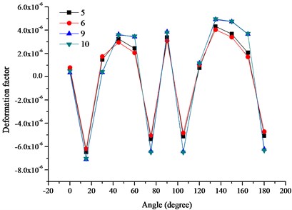
Fig. 7 shows the deformation of the impeller outlet surface. Points 5 and 9 are located on the outlet surface of the impeller on the shroud, while points 6 and 10 are located on the outlet surface of the impeller on the hub. As also shown in Fig. 7 the deformation of points 5 and 9 is better than that of points 6 and 10, which indicates that the deformation of the shroud is larger than that of the hub. The impeller edge connected with the shroud is larger than that of the impeller edge connected with the hub. The largest deformation occurs at an angle of approximately 135 degrees, which indicates that the antiseismic analysis should be conducted at this input angle to conservatively evaluate the antiseismic performance. Furthermore, the analysis of seismic effect on the integral pump structure in multiple input directions cannot be neglected when making an accurate prediction of the antiseismic performance of the pump, because different magnitudes of seismic effect can be found in multispectrum input directions. Thus, the antiseismic analysis procedure for a residual heat removal pump will not be accurate when using an FE tool if the multispectrum input directions are not taken into account.
Fig. 7Deformation of monitoring points on the impeller outlet surface
4.3. Deformation of pressure and suction sides of blade
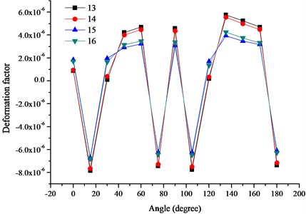
Fig. 8 shows that the trends of the response curves of the blades to different seismic input directions are similar, but the deformation of the impeller edge connected with the shroud is larger than that connected with the hub. The deformation of the pressure and suction sides of the impeller is basically the same; however, the difference between the pressure and suction sides of the impeller is large, in the ranges of 45-60 degrees and 135-165 degrees, respectively. Furthermore, on the shroud, the deformation of the pressure side is larger than that of the suction side of the impeller; on the hub, the deformation of the suction side is larger than that of the pressure side of the impeller. Altogether, the results demonstrate that multiple extreme deformations of the impeller surface fitted with a wear ring, the pressure and suction sides of the blade, and the outlet surface of the impeller occur in the section perpendicular to the shaft. The largest deformation occurs at an angle of approximately 135 degrees for all components, which suggests that the antiseismic analysis should be conducted at this input angle to conservatively evaluate the antiseismic performance. In addition, the installation angle designed for frequent earthquakes should avoid 135 degrees to reduce the deformation effect caused by the seismic force. These results indicate that it is necessary to apply the response spectrum method in multiseismic spectrum input directions during the antiseismic analysis process to estimate the maximum seismic effect in residual heat removal pumps. Furthermore, this can provide a calculation method to determine the input direction with the maximum seismic effect to optimize the design and installation, to increase the antiseismic performance, and to increase the reliability of the pump.
Fig. 8Deformation of monitoring points on the pressure and suction sides of the blade
4.4. Maximum deformation of impeller outlet surface and impeller surface fitted with wear ring
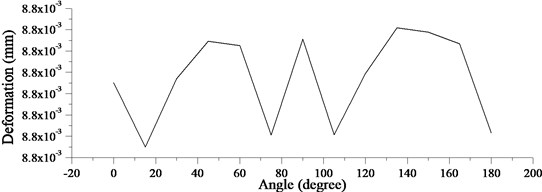
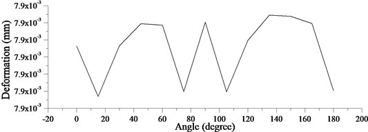
Fig. 9 shows the largest deformation of the impeller surface fitted with the wear ring and the outlet surface of the impeller in different seismic input directions. As shown, the tendency of the response curves to the seismic force is the same. Furthermore, the largest deformation of the impeller surface fitted with the wear ring is 0.0088 mm, which is much smaller than the real clearance between the impeller and the wear ring. The largest deformation of the impeller outlet surface is 0.0079 mm, which is also much smaller than the real clearance between the impeller and the diffuser. Therefore, there is no rubbing or disturbance between the rotating component and the stationary component. These effects should be discerned when the pump structure is being designed and optimized. Compared with previous analytical methods for determining the seismic response in pumps, the result of clearance between the rotor and the stator can instantly and easily assess the integrity and operability of residual heat removal pumps under seismic load.
Fig. 9a) Maximum deformation of the impeller surface fitted with wear ring, b) maximum deformation of the impeller outlet surface
a)
b)
5. Experimental verification
5.1. Pump model
The residual heat removal pump is a single-stage, single-suction, horizontal-orientated low specific speed centrifugal pump. The design parameters of the pump are given in Table 2. The design specific speed of this pump is 104, calculated by Eq. (2):
Table 2Parameters of the pump
Flow rate (m3/h) | 910 | Head (m) | 77 | ||
Rotation speed (r/min) | 1490 | Shaft power | 223 | ||
Blade number | 5 | Impeller outlet diameter (mm) | 513 | ||
Suction diameter (mm) | 270 | Blade width at impeller outlet (mm) | 49 |
5.2. Experimental protocol and experimental setup
Experimental system is composed of two parts, namely, the water circulation system and the data acquisition system. The water circulation system supplies the necessary environment for centrifugal pump operation, whereas the data acquisition system changes all kinds of physical quantities at different conditions to the corresponding electrical signals by using sensors. The final data are directly discernible after processing. The installation diagram of the test system is shown in Fig. 10. The pump, together with the motor, was fixed on a solid base. The inlet gate valve was kept open during the measurement and the outlet gate was used to regulate the flow. The experimental condition is shown in Table 3. The accuracy class could reach the first grade accuracy.
Table 3Experimental condition
Room temperature (°C) | 12 | Inlet pipe diameter (mm) | 350 |
Water temperature (°C) | 28 | Outlet pipe diameter (mm) | 250 |
Atmospheric pressure (MPa) | 0.102 | Rated speed (r/min) | 1490 |
Pressure gauge scale (MPa) | 4 | Motor power (kW) | 355 |
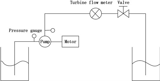
Fig. 10. Installation diagram of the test system
6. Experimental results
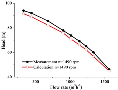
Table 4 shows the delivery head, the shaft power and the efficiency obtained by the experiments for all operating conditions at nominal speed. External characteristic factor head is calculated using the following Eq. (3):
Table 4Experimental results of the model pump
Number | Flow (m3/h) | Head (m) | Shaft power (kW) | Efficiency (%) |
1 | 232.42 | 94.3 | 167.67 | 35.61 |
2 | 332.46 | 93.99 | 179.07 | 47.54 |
3 | 447.92 | 92.01 | 194.8 | 57.63 |
4 | 565.93 | 88.99 | 207.6 | 66.08 |
5 | 685.99 | 85.63 | 218.95 | 73.09 |
6 | 791.64 | 81.36 | 230.92 | 75.98 |
7 | 905.82 | 77.92 | 243.06 | 79.11 |
8 | 906.49 | 77.96 | 243.27 | 79.14 |
9 | 1019.27 | 73.8 | 254.96 | 80.38 |
10 | 1141.44 | 69.22 | 266.37 | 80.81 |
11 | 1238.9 | 65.14 | 274.6 | 80.06 |
12 | 1345.1 | 60.07 | 281.25 | 78.26 |
13 | 1475.77 | 53.29 | 290.61 | 73.72 |
14 | 1573.46 | 46.14 | 295.77 | 66.87 |
Fig. 11 is a comparison of the numerically and experimentally determined delivery head curves for all the operational conditions at the nominal speed. As can be seen, the results of the numerical simulation are in good agreement with those of the experiment. The maximum error between the experimental and calculated values is below 5 %, which confirms the credibility of the calculation.
7. Conclusion
1) The deformation caused by seismic forces is quantitatively calculated by using the seismic response spectrum method and the dynamic analysis in multispectral input directions. The maximum seismic effect in a certain direction provides the most conservative method to evaluate the antiseismic performance in a residual heat removal pump.
Fig. 11Head curve of test pump
2) The clearance between the rotor and the stator is satisfactory for seismic response, according to RCC-M 2000.
3) The seismic response characteristic curves of horizontal pumps are very different from those of vertical pumps, which indicates that the influence of the horizontal asymmetrical structure is different from that of the vertical asymmetrical structure.
4) The deformation of the impeller edge connected with the shroud is larger than that of the impeller edge connected with the hub. The largest deformation occurs at an angle of approximately 135 degrees, which indicates that the anti seismic analysis should be conducted at this input angle to conservatively evaluate the anti seismic performance.
The presented investigation suggests that it is necessary to apply the response spectrum method in multiseismic spectrum input directions to estimate the maximum seismic effects in residual heat removal pumps during the antiseismic analysis process; to seek a calculation method to determine the input direction with the maximum seismic effect to complement the traditional antiseismic analysis; to optimize the design and the installation; to increase the antiseismic performance; and to increase the reliability of the pumps.
References
-
Mohanty W. K., Verma A. K. Probabilistic seismic hazard analysis for Kakrapar atomic power station, Gujarat, India. Natural Hazards, Vol. 69, Issue 1, 2013, p. 919-952.
-
Brillant G., Marchetto C., Plumecocq W. Fission product release from nuclear fuel I. Physical modelling in the ASTEC code. Annals of Nuclear Energy, Vol. 61, 2013, p. 88-95.
-
Mahrenholtz C., Eligehausen R. Dynamic performance of concrete undercut anchors for nuclear power plants. Nuclear Engineering and Design, Vol. 265, 2013, p. 1091-1100.
-
Park H. S., Choi K. Y., Cho S., et al. Experiments on the heat transfer and natural circulation characteristics of the passive residual heat removal system for an advanced integral type reactor. Journal of Nuclear Science and Technology, Vol. 44, Issue 5, 2007, p. 703-713.
-
Kamagata S., Takewaki I. New insights into seismic behavior of building and surrounding soil at Hamaoka nuclear power station during Suruga Bay earthquake in 2009. Soil Dynamics and Earthquake Engineering, Vol. 53, 2013, p. 73-91.
-
Lv X., Yan C., Gu H. Experimental study of density lock in passive residual heat removal system. Power and Energy Engineering Conference (APPEEC), Asia-Pacific, 2012, p. 1-5.
-
Xiang-Bo L., Chang-Qi Y., Hai-Feng G. Experimental study of density lock in passive residual heat removal system. Power and Energy Engineering Conference (APPEEC), Asia-Pacific, 2012, p. 1-5.
-
Suarez L. E., Singh M. P., Rohanimanesh M. S. Seismic response of rotating machines. Earthquake Engineering & Structural Dynamics, Vol. 21, Issue 1, 1992, p. 21-36.
-
Karasudhi P., Wijeyewickrema A. C., Lai T. Seismic response to a prescribed seismogram of a body embedded in a multilayered half space. Computational Mechanics, Vol. 22, Issue 1, 1998, p. 70-76.
-
Dimentberg M. F., Ryzhik B., Sperling L. Random vibrations of a damped rotating shaft. Journal of Sound and Vibration, Vol. 279, Issue 1, 2005, p. 275-284.
-
Zhou Wenjian, Chen Hong, Wen Bangchun Seismic response analysis of reactor coolant pump in nuclear power plant. Journal of Vibration and Shock, Vol. 25, Issue 1, 2006, p. 32-35.
-
Yang Xiaofeng, Zhang Yong, Sun Baitao, Hu Shaoqing Seismic analysis on canned motor pump used in nuclear power generating station. Earthquake Engineering and Engineering Vibration, Vol. 23, Issue 3, 2007, p. 47-53.
-
Zhou Wenxia, Zhang Jige, WangDezhong Analysis and assessment on seismic response of reactor coolant pump in nuclear power plant. Atomic Energy Science and Technology, Vol. 45, Issue 1, 2011, p. 54-59.
-
Farhadi K., Bousbia-Salah A., D’Auria F. A model for the analysis of pump start-up transients in Tehran Research Reactor. Progress in Nuclear Energy, Vol. 49, Issue 7, 2007, p. 499-510.
-
Wu Y. W., Su G. H., Qiu Suizheng, et al. Development of a thermal-hydraulic analysis software for a passive residual heat removal system. Annals of Nuclear Energy, Vol. 48, 2012, p. 25-39.
-
French Association for Design, Construction and In-service Inspection Rules for Nuclear Island Components. Design and Construction Rules for Mechanical Components of PWR Nuclear Islands, 2000.
About this article
This research is supported by the Key Program of National Natural Science Funds of China (Grant No. 51239005) and the National Science and Technology Pillar Program of China (Grant No. 2011BAF14B04) and the Jiangsu Province Project for Innovative Postgraduates of China (Grant No. CXZZ13_06).
