Abstract
Cogging force accounts for important downsides in several aspects, namely causing the speed ripples, inducing vibrations and noises, and increasing the difficulty of position control. All of these negative affects will become more obvious, particularly under light loads and low speeds. So if the cogging force can be kept as minimal as possible, or even completely disappeared, the operational performance of motors will be improved significantly. As our preliminary study indicates, the magnitude of cogging force is influenced by construction of motors, which govern a number of motor parameters. In this paper, the cogging force of a novel type of permanent magnet excited transverse flux linear synchronous motor will be minimized in two steps. First, theoretical analysis will be employed to obtain the most influential parameter on cogging force. Second, Taguchi’s method including 2D finite element analysis is applied to minimize the cogging force. Analytical and simulation results indicate the usefulness of our approach in practice.
1. Introduction
Since permanent magnet linear electric machines are widely used, cogging force has become a major issue because its negative effects such as speed ripples [1], inducing vibrations and noises [2, 3], and increasing the difficulty of position control [4]. In order to keep a good performance of a PM linear motor, the above mentioned negative effects should be suppressed as far as possible. In an iron core permanent magnet linear motor, the cogging force appears with the interaction between permanent magnets and armature core. For reducing cogging force, many techniques have been proposed in the following. First, concerning smaller flux in the air gap, Sebastian et al. have showed that the cogging force increases when the permanent magnet has a larger remanence [5]. Second, regarding proper selection of pole and slot combination, when the relative position between magnet pole and slot changes, the cogging force can be reduced. It means that the pole number and slot number are not equal [6, 7]. Third, considering adjusting air-gap length, obviously if the air-gap length becomes larger, the magnetic field in air-gap will be weaker. This can lead to a smaller cogging force [8]. Fourth, skewing slots or magnets is the most used method to reduce cogging force because its effect is better. From some studies, the best skewed angle should be equal to the thrust ripple cycle [5, 9]. Fifth, with auxiliary slots, the distribution of air-gap magnetic flux will become more uniform if stator slots are designed with embedded such slots. Therefore, the cogging force can also be reduced [10, 11]. Sixth, using semi-closed slots can reduce the cogging force because the magnetic field in air-gap becomes more uniform in comparison with opened slots [8].
This paper aims at minimizing the cogging force of the permanent magnet excited transverse flux linear synchronous motor (PMTFLSM). Featuring a structure of cross-shaped cores of the translator, the afore-mentioned second method will be applied to this study. The theoretical cogging force can be obtained directly from partial differentiation of the magnetic co-energy in the air gap. Through theoretical analysis, we come first to find how each machine parameter affects the cogging force. Since the machine parameters have different influence on cogging force, Taguchi’s parameter method coupled with 2D FEM software Comsol Multiphysics is then used to minimize the cogging force for finding the best design parameters of the PMTFLSM.
2. A new configuration of the PMTFLSM
The structure of transverse flux linear motors can be classified in several types [12], among which the U-shaped iron core is most common. This study is targeted at a novel PM transverse flux linear motor. It has a special design in the translator with cross-shaped cores. The construction of the PMTFLSM is shown in Fig. 1 [13]. The permanent magnets are set on a soft magnetic back iron in the stator and the motor windings are wrapped around on the cross-shaped core set. The polarity of the first permanent magnet can be selected either “N” or “S”, so that the beginning of the magnet rows in the cross section can be implemented with four rows in an “N-N-N-N”, “N-N-S-S”, or “N-S-N-S” manner. The magnetic pole division can have different dimensions per requirements. The translator is composed of independent cross-shaped core sets which are made from soft magnetic materials. The pole pitch of the translator can be selected for a smallest cogging force. The number of cross-shaped core sets depends on motor power. A high motor power requires more cross-shaped core sets. In this study, the translator contains six cross-shaped core sets. The construction parameters of PMTFLSM are shown in Fig. 2 and defined as: Δx: axis displacement between magnet and translator; τR: translator pole pitch; τM: magnetic pole pitch; hM: magnet height; bM: magnet width; bZ: width of the tooth head; lg: the air gap length. The direction of motion is referred to as the x-axis.
Fig. 1Schematic of the PMTFLSM: 1 – Stator back iron, 2 – Cross-shaped core, 3 – Permanent magnet, 4 – Winding, 5 – Translator shaft

Fig. 2Definition of motor parameters

3. Determination of the theoretical cogging force
In order to simplify calculation, we assume that the magnetic circuit has no flux leakage and saturation. According to Fig. 2, the no-load magnetic induction B(x) excited by the permanent magnet in the air-gap is periodic and can be represented with Fourier expansion in Eq. (1).
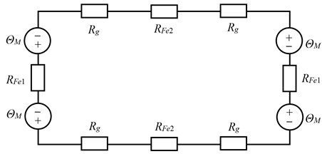
where Bg is the magnetic induction in the air-gap caused by permanent magnet. The construction of the PMTFLSM shown in Fig. 1 has a closed magnetic flux path with four magnet poles and air-gaps. The magnetic equivalent circuit diagram is represented in Fig. 3, where Rg is the magnetic resistance of air-gap, RFe1 and RFe2 are the magnetic resistance from cross-shaped core and back iron, respectively. Assuming that a permanent magnet with height hM, relative permanent permeability μrrec and remanence Br is used to a magnetic circuit with infinitely magnetic permeability of the ferromagnetic material, Bg can then be approximated as in Eq. (2) [5].
Fig. 3Magnetic equivalent circuit of PMTFLSM: ΘM: Magneto-motive potential of the permanent magnet, Rg: Magnetic resistance of the air gap, RFe1: Magnetic resistance of the cross-shaped core, RFe2: Magnetic resistance of the back iron
In order to determine the cogging force, the magnetic co-energy in the air-gap must be calculated. The magnetic co-energy w'(x,y,z) in the air gap under individual tooth head can be obtained by Eq. (3) in the Cartesian coordinate system:
where li is effective air gap length and lM is the length of permanent magnet. Substituting Eq. (1) into Eq. (3) gives the magnetic co-energy w'(x,y,z):
∙{bZ+τM2(2k-1)π[sin(2(x+bZ2)(2k-1)πτM)-sin(2(x-bZ2)(2k-1)πτM)]}.
When the translator changes its position in x-direction, the magnetic co-energy in the air-gap can make a difference as well. Since the magnetic co-energy is a function of motion position, the cogging can be found by partial derivative of Eq. (4). Due to the symmetrical configuration of PMTFLSM and by the guidance of the translator, the force components Fy and Fz will disappear. Therefore, the cogging force Fx at the individual tooth head can be generalized with pole axis displacement Δx. From Eq. (4) the analytically computed cogging force density Fcj(x) of individual tooth head is given by Eq. (5):
∙{cos[2(x+bZ2-(j-1)∆
In this study, six cross-shaped cores 6) were used to compose the translator. The resulting cogging force is computed from the arithmetic sum of the cogging force arising at the individual tooth head [11]. With reference to Eq. (5), the resulting cogging force can be written as:
where and .
4. First step to reduce cogging force
The cogging force of PMTFLSM depends on several motor parameters, e. g., pole axis displacement that is implied by magnet pole division and translator pole pitch , magnet width , tooth head width , air-gap length , magnet height , as well as the remanence of the permanent magnet . These factors possess different potencies on the cogging force. Each factor has a best value that can lead to cause a local minimal cogging force. The combination of these best values is the first-step to minimize the cogging. However, the best combination is yet to be found despite involved interactions among them. In what follows, the motor parameters , , , and will be selected to make a comparison for reducing the cogging force because they are the dominant factors for affecting the optimum combination.
Table 1Basic data of motor parameters
Symbol | Description | Unit | Value |
Magnet pole pitch | mm | 18.0 | |
Translator pole pitch | mm | 24.0 | |
Magnet remanence | T | 1.25 | |
Magnet width | mm | 12.0 | |
Magnet thickness | mm | 3.0 | |
Tooth width of cross-shaped core | mm | 8.4 | |
Air gap length | mm | 1.0 |
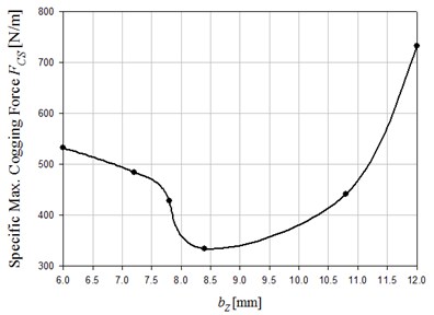
Using the basic machine parameters of Table 1, 2D FEM simulations and theoretical calculations for the cogging force of individual tooth head and its sum value are shown in Fig. 4. Analytical and simulated results indicate how magnet pole division and translator pole pitch result in cogging force (Fig. 5.) Cross-comparing results of Figs. 5-7 lead us to find that the ratio of can affect the cogging force from 0 to 7000 N/m (according to simulations). It can be confirmed as well that the ratio of translator pole pitch to magnet pole division has the dominant influence on the cogging force. If motor parameters that can cause a local minimal cogging force are selected, the best combination can be determined from Figs. 5-7 for 24.0 mm, 18.0 mm, 12.0 mm, and 8.4 mm. This combination can reduce the cogging force to 33.35 N when the magnet length is set to 50.0 mm.
Fig. 4Individual and total cogging force
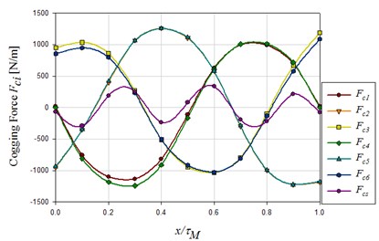
Fig. 5Influence of τR/τM on cogging force
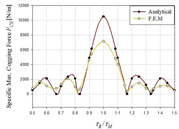
Fig. 6Influence of bM on cogging force
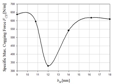
Fig. 7Influence of bZ on cogging force
5. Second step to reduce cogging force
Taguchi’s method is mainly used in quality engineering. Its advantages are to improve product quality, to reduce the number of experiments, and to finish the experiment effectively [14]. Taguchi’s method emphasizes a low-cost components, materials and processes to achieve high quality products, so that this method is widely used in industry [15, 16]. The basic spirit of Taguchi’s method is through statistical analyses of orthogonal array and corresponding ratio (signal-to-noise) to obtain optimized parameters. The orthogonal array is formed by experimental factors and levels. A proper selection of experimental factors and levels can get a better design quality. The steps for using Taguchi’s method to reduce cogging force of the PMTFLSM are as follows: 1) decision of the control factors and its levels; 2) selection of a proper orthogonal array; 3) implementation of experiments at orthogonal array; 4) calculating the average value and ratio of experimental results; 5) construction of corresponding ratio diagram; 6) confirming the best level combination and getting the optimized results.
By using Taguchi’s method, the orthogonal array must be set up with selected factors and levels [17]. In our study, the orthogonal array contains four selected experiment factors and three levels. With reference to the first-step minimization of cogging force, the four selected factors , , , and represented in Fig. 8 are translator pole pitch , magnet pole division , magnet width , and tooth head width , respectively. Each factor has three levels as shown in Table 2. The orthogonal array and its experimental results are listed in Table 3. Each experiment is conducted based on 2D FEM.
Fig. 8Selected control factors

Table 2Selected parameters and its level
Parameters | Code | Level | ||
1 | 2 | 3 | ||
Magnet pole division [mm] | 17.95 | 18.0 | 18.05 | |
Translator pole pitch [mm] | 23.95 | 24.0 | 24.05 | |
Magnet width [mm] | 10.0 | 12.0 | 14.0 | |
Tooth head width [mm] | 7.4 | 8.4 | 9.4 | |
Table 3L9(34) orthogonal array
Experiment | Factor | Cogging force [N] | |||
1 | 17.95 | 23.95 | 10.0 | 7.4 | 76.4656 |
2 | 17.95 | 24.0 | 12.0 | 8.4 | 29.6952 |
3 | 17.95 | 24.05 | 14.0 | 9.4 | 32.4529 |
4 | 18.0 | 23.95 | 12.0 | 9.4 | 15.667 |
5 | 18.0 | 24.0 | 14.0 | 7.4 | 26.4 |
6 | 18.0 | 24.05 | 10.0 | 8.4 | 66.878 |
7 | 18.05 | 23.95 | 14.0 | 8.4 | 45.5817 |
8 | 18.05 | 24.0 | 10.0 | 9.4 | 50.83789 |
9 | 18.05 | 24.05 | 12.0 | 7.4 | 52.2353 |
Once the experimental results in Table 3 have been obtained, the mean value of each influence factor can be found and listed in Table 4. The mean value analysis is used to assess the affecting strength of each factor.
For Taguchi’s method, the ratio (or Signal to Noise ratio) is usually used as an index of quality. Quality is defined as the ratio between the meaningful signal and background noise. A larger ratio indicates better quality. In this study, the quality characteristics of cogging force should reflect “the-smaller-the-better” notion. The corresponding ratio can be calculated by Eq. (7) [18]:
In Eq. (7), represents the quality characteristics of cogging force and is defined as the experiment number of each group. According to the mean values in Table 4, the corresponding ratio values of cogging force can be determined and listed in Table 5. And its response is shown in Fig. 9. With reference to Fig. 9, the best combination of control factor for reducing cogging force can be selected to A2-B2-C2-D3. The optimized motor parameters may be differed from the original data. The selected motor parameters after Taguchi’s method are listed in Table 6.
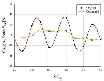
The best selected combination A2-B2-C2-D3 of control factor is applied to calculate the cogging force by the 2D FEM again. The simulated results are compared with the original motor parameters of the PMTFLSM, as shown in Fig. 10 and Table 7. Setting the magnet length to 50 mm, the maximal cogging force has been reduced from 33.35 N (before optimization) to 10.62 N (after optimization). The reduced amplitude reaches 29.36 N. In other words, the reduction amounts to 68.16 %, a marked improvement.
Table 4Mean value of each factor
Level | Mean value [N] | |||
1 | 46.20457 | 45.90477 | 51.7003 | 64.72716 |
2 | 36.315 | 35.64436 | 47.38497 | 32.5325 |
3 | 49.55163 | 50.52207 | 32.98593 | 34.81153 |
Table 5S/N value of each factor
Level | S/N value | |||
1 | –33.294 | –33.237 | –36.222 | –34.27 |
2 | –31.202 | –31.04 | –30.246 | –33.513 |
3 | –33.901 | –34.07 | –30.834 | –30.367 |
Table 6Motor parameters before/after optimization
Motor parameter | Control factor | Before optimization | After optimization |
Magnet pole division [mm] | 18.0 | 18.0 | |
Translator pole pitch [mm] | 24.0 | 24.0 | |
Magnet width [mm] | 12.0 | 12.0 | |
Tooth head width [mm] | 8.4 | 9.4 |
Table 7Optimization results
Item | Before optimization | After optimization |
Maximal cogging force [N] | 33.35 | 10.62 |
Reduced amplitude [N] | 22.73 | |
Percentage of reduced amplitude [%] | 68.16 | |
Fig. 9Corresponding S/N ratio values for cogging force
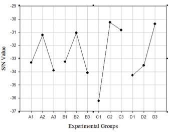
Fig. 10Comparison of cogging forces
It will also be pointed out that the effects of motor parameters on cogging force and thrust are normally in conflict. When a set of selected parameters can lead to a minimal cogging force, the thrust may not reach the maximal value. Therefore, it must be found a compromise between cogging force and thrust.
6. Conclusions
The special structure with corss-shaped core of the PMTFLSM has been introduced in this paper. Theoretical analysis and 2D FEM were applied to determine the cogging force which can be affected by several motor parameters. Among these parameters, translator pole pitch, magnet pole division, magnet width, and tooth head width are relevant parameters which possess dominant influence on cogging force. Theoretical analyses provide the first-step minimization through finding the local minimal value of cogging force. The second-step for minimizing the cogging force is using Taguchi’s method to reach the goal. After two steps of minimization including 2D FEM, the cogging force of the PMTFLSM can be reduced evidently. The results of this paper can be considered for designing a PM linear motor. In addition, the optimization of cogging force can also offer useful information to study motor thrust of the PMTFLSM.
References
-
Bianchi N., Bolognani S., Cappello A. D. F. Back EMF improvement and force ripple reduction in PM linear motor drives. Power Electronics Specialists Conference, IEEE 35th Annual, Vol. 5, 2004, p. 3372-3377.
-
Islam R., Husain I. Analytical model for predicting noise and vibration in permanent magnet synchronous motors. IEEE Transactions on Industry Application, Vol. 46, Issue 6, 2010, p. 2346-2354.
-
Cassat A., Espanet C., Coleman R., Burdet L., Leleo E., Torregrossa D., M’Boua J., Miraoui A. A practical solution to mitigate vibrations in industrial PM motors having concentric windings. IEEE Transactions on Industry Application, Vol. 48, Issue 5, 2012, p. 1526-1538.
-
Werner U., Schuettler J., Orlik B. Position control of a transverse flux motor with reduced torque ripples for direct servo-drive applications using shaped currents with harmonics control. 12th European Conference on Power Electronics and Applications, 2007.
-
Gieras J. F. Permanent magnet motor technology: design and applications. CRC Press, 2010.
-
Miller T. J. E., Hendershot Jr. J. R. Design of brushless permanent magnet motors. Oxford, Clarendon Press, 1994.
-
Hwang C. C., Wu M. H., Cheng S. P. Influence of pole and slot combinations on cogging torque in fractional slot PM motors. Journal of Magnetism and Magnetic Materials, Vol. 304, Issue 1, 2006, p. 430-432.
-
Lim K. C., Woo J. K., Kang G. H., Hong J. P., Kim G. T. Detent force minimization in permanent magnet linear synchronous motors. IEEE Transactions on Magnetics, Vol. 38, Issue 2, 2002, p. 1157-1160.
-
Gieras J. F., Piech Z. J. Linear synchronous motor: transportation and automation systems. CRC Press, 2000.
-
Rizzo M., Savini A., Turowski J. Influence of number of poles on the torque of DC brushless motors with auxiliary salient poles. IEEE Transactions on Magnetics, Vol. 27, Issue 6, 1991, p. 5420-5422.
-
Wu Y. C., Hong Y. C. Cogging torque and ripple torque reduction of a novel exterior-rotor geared motor. Journal of Vibroengineering, Vol. 14, Issue 4, 2012, p. 1477-1485.
-
Evers W., Henneberger G., Elschenbroich H. A transverse flux linear synchronous motor with a passive secondary part. 16th Int. Conf. on Magnetically Levitated Systems and Linear Drives, 2000, p. 393-397.
-
Tseng W. T., Wang J. J. Cogging force analysis for design of a cross-shaped core permanent magnet linear motor. 15th International Conference on Electrical Machines and Systems, 2012.
-
Roy R. K. Design of experiments using the Taguchi method. Wiley, 2001.
-
Hwang C. C., Lyu L. Y., Liu C. T., Li P. L. Optimal design of an SPM motor using genetic algorithm and Taguchi method. IEEE Transactions on Magnetics, Vol. 44, Issue 11, 2008, p. 4325-4328.
-
Lindman H. Analysis of variance in experimental design. Springer-Verlag, 1992.
-
Kacker R. N., Lagergren E. S., Filliben J. J. Taguchi’s orthogonal arrays are classical designs of experiments. Journal of Research of the National Institute of Standards and Technology, Vol. 96, Issue 5, 1991, p. 577-591.
-
Islam M. S., Islam R., Sebastian T., Chandy A., Ozsoylu S. A. Cogging torque minimization in PM motors using robust design approach. IEEE Transactions on Industry Application, Vol. 47, Issue 4, 2011, p. 1661-1669.
About this article
The authors wish to express their appreciation to National Yunlin University of Science and Technology, and National Science Council Taiwan under grant NSC 98-2218-E-224-008 for providing the research equipment of this study.
