Abstract
Since the field of microfluidics is vastly improving and developing, and piezoelectric actuators offer good control on a micrometer scale, this work was created as a combination of the two. A microfluidic chip with an embedded piezoelectric actuator was designed and constructed using polydimethylsiloxane as the main material. The chip was experimented on by varying both mechanical and electrical properties. Performance dependencies of volumetric flow rate and input waveform were described and analyzed. Moreover, beneficial phenomena were discovered and analyzed using high-speed microscopy and digital image analysis. A situation where control of microfluidic flow direction could potentially be available was achieved. Other promising results showed new potential applications for piezoelectric actuation in microfluidic systems.
1. Introduction
The field of microfluidics is experiencing a vast improvement and increased applications in recent decades. The applications range all the way from basic sciences, like chemistry, physics and biology to most engineering disciplines. The emergence of nanotechnology, giving significant input to pretty much every industrial application, has influenced the development of microfluidics as well. These two scientific areas combined are creating a way for the replacement of conventional systems and methods by lab-on-a-chip systems [1].
Since the cell is the basic structural unit of all living organisms, the ability to distinguish and sort different cell types is essential in biology, food industry, medicine and physiology. It enables various tasks to be completed, such as protein engineering, cell engineering, quality assurance, diagnostics and filtering. There are several different methods e.g. Single Cell Sorting [2], Fluorescent Activated Cell Sorting [3] and Magnetic Cell Sorting [4].
Most of the methods involve flowing cells in a liquid jet and manipulating the targeted ones using electric and/or magnetic fields. In particular, Fluorescent Activated Cell Sorting technique uses electrostatic deflectors, which direct charged droplets containing target cells towards collecting containers. Liquid jet is designed in such a way, that every individual droplet that detaches itself from the jet can only contain one cell. If the detector recognizes the target cell, the whole liquid jet gets charged and once the droplet detaches – becomes neutral again. The charged droplet then is directed towards collecting containers by using electrostatic deflectors [3]. Although this technique is reliable and widely used, it involves charging the sample, which might not be appreciable.
The quest to miniaturize the cell sorting has led to the lab-on-a-chip principle. This technique involves flowing a stream of fluid through 100-micrometer scale channels in a match box sized chip. The chip is usually made of polymethyl methacrylate (PMMA), polydimethylsiloxane (PDMS) or quartz and the channels fabricated using soft-lithography. Lab-on-a-chip is closely related to and overlaps with microfluidics which describes primarily the physics, the manipulation and study of minute amounts of fluids. Since the amounts of fluids are so small, the flow is generally laminar and can be easily observed and analyzed by conventional microscopy. For better analysis of sudden processes high-speed camera can be used to enable the observation in slow motion.
2. Experimental methodology and equipment
2.1. Idea
The theory behind the idea is based on piezoelectric actuator’s ability to provide a single, sudden and strong actuation of fluid in a direction perpendicular to the flow of the sample. The layout of the chip should consist of one main stream channel, a channel perpendicular to it forming a cross-shaped structure and a buffer chamber roughly the size of the actuator. See Fig. 1 for an explanation of the idea.
Fig. 1Idea representation: a) before actuation, detected cell (red spot) travels in the main stream channel (left to right) to the crossroad area; b) during actuation, sudden expansion of the piezoelectric actuator causes the buffer fluid (green) to replace the small volume of the fluid under inspection containing the target cell; c) after actuation, the target cell carries on through the secondary channel and into a sorted cells’ compartment

2.2. Methods and Materials
2.2.1. Piezoelectric Actuator
All things considered, a piezoelectric actuator of type AE0203D04F offered by Thorlabs® [6] was selected. The dimensions of it were: mm (length × width × height). Displacement offered by this device at a recommended voltage (100 V) is . This means, that using this actuator it would be possible to achieve a displacement of μl volume by a single actuation.
2.2.2. Design and Fabrication
First of all, the microfluidic circuitry to be used for tests and experiments is designed using DraftSight from Dessault Systems software. As a next step, designed circuitry is printed in black and white on an A1 format sheet of paper. The image is then photographed using high resolution black and white film Adox CMS 20 (ISO10). The shots are made with a Pentax MZ30 SLR camera. A very long exposure time yields a very high contrast in the negative. Lastly, the photo-negative film is developed using a special high contrast document developer SPUR Docu SHC.
Next, the fabrication process resumes in a cleanroom. In this particular case, the fabrication was done in Southern Denmark University’s Class 100 (ISO 5) cleanroom. First, SU-8 2050 photoresist is spin-coated on a standard silicon wafer resulting in 85 µm film thickness. After that, the wafer with SU-8 on is exposed to UV light for 45 seconds in a mask aligner using previously developed photo-negative as the mask. The exposed parts of SU-8 become insoluble. The photoresist is then developed in SU-8 developer, removing the unexposed parts of it. This way developed masters are cut into predefined dimensions using a dicing saw.
Next step is to prepare the PDMS to be used as the main material of the microfluidic chip. Materials for that are PDMS polymer and PDMS curing agent. Both components are weighted to compose a 1 to 8 ratio of curing agent to polymer and mixed well.
The piezoelectric actuator is positioned first on the master by putting a small droplet of uncured PDMS on it and then holding the actuator in place while heating it up to the curing temperature. The master with the actuator is fixed in a specifically designed mold which is then filled with PDMS. Finally, the mold is placed on a hot plate and held until PDMS is cured. All heating procedures are carried out at lower than usual temperatures, since longer exposures to temperatures over 80 °C can depolarize the piezoelectric actuator.
After disassembling and removing the cured chip out of the mold, the top lid is fabricated. A thin layer of PDMS with a much higher concentration of curing agent is deposited on a small glass plate and cured. It is then peeled off and carefully placed on the top of the chip, on the channel’s side. The chip is then heated again. Since the curing agent does not get consumed in the curing process, a much higher concentration of it in the lid causes diffusion to take place. That way, the lid crosslinks itself with the chip. This is made to avoid the common sealing in the oxygen plasma, since it may have a negative effect on the actuator.
2.2.3. Experimental Setup
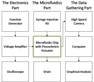
Experiments were carried out in the Southern Denmark University’s microfluidics lab. The setup consists of electronics part, data gathering part and the actual microfluidic device.
The electronics part consisted of:
1. Function generator (Tektronix AFG3022B): in order to be able to control the piezoelectric actuator with various waveforms and amplitudes;
2. A voltage amplifier for piezoelectric devices (TreK Model PZD350): necessary to amplify the signal generated by the generator up to recommended operation voltage of the piezoelectric actuator (100 V);
3. Oscilloscope: to monitor both signals – the one generated and the one amplified.
The waveforms tested were square wave and saw-tooth. A multitude of parameters, such as frequency, duty cycle, amplitude, offset were varied with each of them in order to distinguish any pattern of influence to the device’s performance.
Microfluidic part consisted of:
1. Syringe injection kits (SK-500I and Harvard Apparatus PHD 2000): obligatory to drive the fluid through the channels on the chip;
2. 10 ml syringes filled with dyed and clear water: to be able to distinguish the meniscus between both flows;
3. Specifically designed chuck to mount the microfluidic chip;
4. Rubber tubes.
The syringe injection kits have only one parameter – flow rate. Therefore, for the most part the tests were varied by altering the ratio between the flow rates of the fluids being injected. The aim of that was to achieve a stable situation, where actuation could be clearly visible and beneficial.
The data gathering part consisted of:
1. High speed camera (Pentax MZ30 SLR): set up for slow motion capturing;
2. Lighting setup;
3. Computer.
Fig. 2Structure of experimental setup

The whole progress of tests (filling, setting up of stable situations etc.) is monitored in the display to which the camera is plugged in to via HDMI connection. The actuation processes are recorded using the high speed camera at 400 frames per second. This way, 3 seconds of real time are converted to 40 seconds of slow motion time. The recordings are transferred to computer and analyzed.
The software used was ImageJ [7]. The videos are converted into a series frames and position change of the meniscus is measured and plotted against time. The actual displaced volume is then approximated using the following formula: , where is the position of the meniscus between the two streams before actuation relative to the edge of the channel; is the position of the meniscus between the two streams during actuation relative to the edge of the channel; is the volumetric flow rate of the main stream; is the period of actuation.
3. Results
All experiments with all the different channel setups were carried out by changing the overall volumetric flows of the fluids, their ratios (in search of beneficial situations) as well as the voltage amplitude, frequency and waveform of the actuating signal. The intervals of parameter variations were as follows:
1. Volumetric flow rate: 0.1 ml/h ~ 20 ml/h;
2. Volumetric flow rate ratios (main fluid/buffer fluid): 0.1 ~ 10;
3. Actuating signal voltage amplitude: 20 V ~ 120 V;
4. Actuating signal frequency: 1 Hz ~ 100 Hz;
5. Actuating signal waveform: sine, square, pulse, saw-tooth.
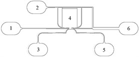
After several tryouts of various channel layouts, the best results have been achieved using a layout as shown in figure 3. In this particular case, the fluid under inspection enters the chip through the main inlet (1). This flow is then compressed by two buffer fluids injected through inlets 2 and 3. One of those buffer fluids also fills up the chamber resting on top of the piezoelectric actuator, which at a certain moment creates an increase of pressure of that particular buffer fluid, causing the main fluid, under certain circumstances, to switch channels and exit through the outlet 5 instead of 6.
Fig. 3Channel layout of the microfluidic chip: 1) Main test fluid inlet; 2) buffer fluid inlet #1; 3) buffer fluid inlet #2; 4) chamber of fluid to be actuated; 5) sorted cells’ outlet; 6) main fluid outlet

Parameters, with which the best results were observed:
1. Volumetric flow rates:
a) Main fluid: 0.5 ml/h
b) Buffer fluids: 12 ml/h
2. Actuating signal voltage amplitude: 120 V
3. Actuating signal frequency: 10 Hz (this is only to make the observation easier – the phenomenon can also be noticed at higher frequencies)
4. Actuating signal waveform: 0 % symmetry saw-tooth.
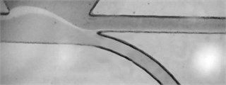
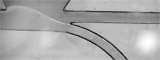
See figures 4 and 5 for an overview of a flow redirecting phenomenon (possible cell-sorting situation).
Other results of notice, achieved with other kinds of channel setups were as follows:
⦁ The overall flow rate of the fluids have no effect on the performance of the piezoelectric actuator, only the ratio.
⦁ Saw-tooth actuating waveform yields around 50 % better performance of the piezoelectric actuator in this particular setup.
⦁ Other potentially beneficial situations were observed, e.g. channel shutdown, precision dosing.
Fig. 4Fluid steady state: The main fluid (travelling left to right, transparent) is compressed by the two buffer fluids from both sides (grey). Whole volume of main fluid exits through the main outlet

Fig. 5Fluid state at the moment of actuation: The main fluid is redirected to the other channel by a sudden increase of the buffer fluid (above) pressure. Whole volume of main fluid exits through the secondary outlet

4. Conclusions
Three different modifications of microfluidic lab-on-a-chip with an embedded piezoelectric actuator were designed, constructed and experimented on, the last of which was presented in this article. Each prototype steadily approached the idea of microfluidic cell sorting with the help of piezoelectric actuation, ultimately resulting in a promising discovery of flow redirection.
The lab-on-a-chip systems were experimented on by varying both mechanical and electrical properties, such as flow rates and their ratio, actuating voltage amplitude and frequency as well as signal waveform. In addition to the discovery of possible cell sorting setup, other potentially beneficial phenomena were observed.
Further study requires looking into improvements of channel geometry, piezoelectric actuator geometry and position, feedback and control systems.
References
-
Kumar C. S. Microfluidic Devices in Nanotechnology. Hoboken, NJ, USA, Wiley, 2010.
-
DEPArray™. Silicon Biosystems, 2013, http://www.siliconbiosystems.com/deparray-technology-faqs
-
Flow Cytometry. Oregon State University, 2013, http://www.unsolvedmysteries.oregonstate.edu/ flow_06.
-
Magnetic-activated cell sorting. Meltenyi Biotech, 2013, https://www.miltenyibiotec.com/en.aspx.
-
Fluorescence activated cell sorting of live cells. Abcam, 2013 http://www.abcam.com/index.html? pageconfig=resource&rid=12803.
-
Thorlabs, http://www.thorlabs.com.
-
ImageJ, http://rsbweb.nih.gov/ij/.
-
Li M., Li S. B., Cao W. B., Li W. H., Wen W. J., Alici G. Improved concentration and separation of particles in a 3D dielectrophoretic chip integrating focusing, aligning and trapping. Microfluidics and Nanofluidics, 2013, p. 527-539.
-
Murray C., McCoul D., Sollier E., Ruggiero T., Niu X. F., Pei Q. B., Di Carlo D. Electro-adaptive microfluidics for active tuning of channel geometry using polymer actuators. Microfluidics and Nanofluidics, 2013, p. 345-358.
-
Nawarathna D., Norouzi N., McLane J., Sharma H., Sharac N., Grant T., Khine M. Shrink-induced sorting using integrated nanoscale magnetic traps. Applied Physics Letters, 2013.
-
Song Y. X., Peng R., Wang J. S., Pan X. X., Sun Y. Q., Li D. Q. Automatic particle detection and sorting in an electrokinetic microfluidic chip. Electrophoresis, 2013, p. 684-690.
-
Qing-Hua Q. Advanced Mechanics of Piezoelectricity. Springer, Berlin, Heidelberg, 2013.
About this article
This research is funded by the European Social Fund under the Project „Microsensors, microactuators and controllers for mechatronic systems (Go-Smart)“ (Agreement No. VP1-3.1-ŠMM-08-K-01-015).
