Abstract
In the background of polar research robot equipment, this paper presents a kind of control system of large-size spherical robot, and resolves the problems of balance and motion control of spherical robot by fuzzy control algorithm. Through comparison among different control methods, we took one practical and feasible way. On the basis of balance problem, we proposed a relative control strategy. Especially on the problem of the deflection of minor axis, we analyzed it and further designed a specialized fuzzy controller to control the deflection of this robot, this helped to solve the uncontrollable problem of the robot. The algorithm easily suffers from environmental influence, for this reason, we proposed a kind of optimization algorithm based on reference model by correcting coefficient. It can make the algorithm adapt environment automatically when the landform remain unchanged and implement control of the robot by amending the parameter of fuzzy algorithm’s output. Finally, we implemented a motion control experiment for our self-design robot. The experimental data showed the validity and practicability.
1. Introduction
With the further scientific investigation of polar region all around the world, different kinds of unmanned vehicle robots are used in the investigation increasingly. However, traditional robot usually will suffer great difficulties because of the harsh climate and geological conditions. So, more and more specialized robots have been developed to apply in the polar region. As a type of robot that owns special shape and unique property, it should be taken seriously despite of its short development time and immature technology.
The biggest advantage of spherical mobile robot in the harsh environment is its highly symmetrical structure, so it won’t be bothered by the problem of inversion and overturn during obstacle crossing. The symmetrical structure of robot makes it keep legal situation in any position. Good flexibility and turning ability is its necessary guarantee to avoid cliff and trap even on the dangerous surface of ice. The omnidirectional movement characteristics and the very little turning radius which can be negligible fit the requirement exactly. Especially for the large-size spherical robot, when it comes gully and dark cave, the robot can pass them relied on its large dimension. All of these advantages take great merits for the high-intensity and high-risk work.
The most profound difficulty of spherical mobile robot is the problem of motion control. Motion control is the basis of robot. Spherical robot has variable driving modes, but none of the method is recognized. On the one hand, multiple actuated modes bring the innovation of structures, on the other hand, it results in the lag of control algorithm. Sphere is hard to balance despite the uniqueness of symmetrical structure, this characteristic also increases the difficulty of research especially how to keep balance facing the disturbance of changeable landform and the outside world. So it’s worthy of designing a type of control software that meets the requirement, equipping with practical hardware platform.
2. Balance control for eccentric structure of spherical robot
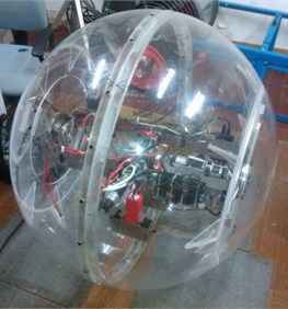
This two-motor driving robot has an eccentric structure, as shown in the Figs. 1 and 2, its small turning radius is a great advantage competing with vehicle. But there is also some gap to reach omnidirectional rolling theoretically. Generally, ideal sphere possesses superb flexibility in ideal condition. If the ball can rotate 90 degrees about x-axis, we defined that it owns the ability of omnidirectional motion. On the other hand, the ball can achieve linear motion only if there is no deflection about x-axis. However, if the output torque of short shaft motor is zero and there is point contact between ball and ground at that time, it may lead robot deviate from balance position because of trim error and uneven ground. So, we need more precise algorithm to offset this error. It may cause slow response, shake and out of control by using driving short axis motor to keep balance. In addition, the proportion of counterweight’s mass is too small among the total mass to keep the sphere balance, and hysteretic response may appearance. The control performance will sharply drop if the mass of robot is asymmetrical and uneven which actually is inevitable. But increasing the mass of eccentric block is also restrained by structural dimension and design requirement. And the mass of shell and frame increase drastically because of its large size, so the mass of eccentric block is restrained again by the limited load capacity of frame which supports motors. In a word, the control algorithm design of large-size spherical mobile robot is urgent to be solved due to the congenital deficiency of eccentric structure.
Fig. 1The structure of SMR
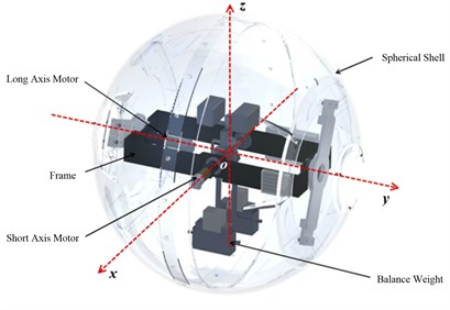
Fig. 2The picture of large-size SMR
2.1. Selection of control algorithm
The large-size spherical robot in this paper is high nonlinear and non-holonomic, its motors are highly coupled, these properties result in hard control using classic control algorithm. The irregularity of robot has a great effect on the uncertainty of dynamical equation which result in the infeasibility of using dynamical equation merely to obtain suitable control method. In addition, spherical mobile robot is much sensitive to the disturbance of outside world including landform, so ordinary algorithm is easily unstable. For above problems, it is a significant issue to choose a suitable algorithm to control the deflection.
We have compared some kinds of common algorithms like PID, CMAC, BP and fuzzy control. Traditional PID algorithms are simple and mature, they can verify the algorithm by collecting PID parameters, but later we found that collecting PID parameters and delimiting dead zone again and again is still hard to keep the robot robust. So, classical PID algorithm will not be concerned.
As intelligence algorithm, the property of BP and CMAC is ability to study. BP neural network is widely applied on pattern recognition, function fitting and so on. CMAC is widely applied on robot control because of the excellent real-time performance and the simpleness of calculation. But neither of them are suitable for spherical mobile robot directly. First of all, considered the high nonlinearity of robot, the generalization ability of BP is doubtful, and its complicated calculation is inadaptable to real-time control. CMAC will occupy enormous room which will exceed the range of driving hardware. Second, the biggest problem of these two algorithms is the absence of exact dynamical model to simulate and online study. Given the lack of dynamical model and the motion characteristic of robot, we determined to adopt fuzzy control algorithm which includes the thought of experts.
The advantage of fuzzy control is that it can integrate the perceptual knowledge, intuitive feeling and rational analysis of people into calculation without exact dynamical model. For example, it was applied to inverted pendulum successfully. So, we took fuzzy control algorithm to solve the deflection of robot.
2.2. Design of angle controller based on fuzzy control
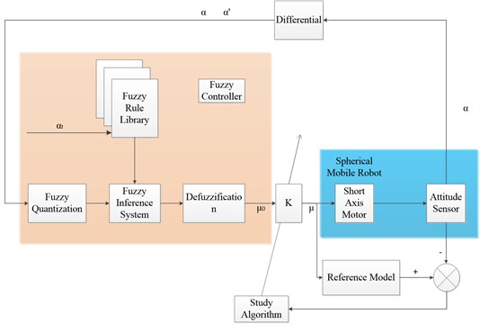
We took fuzzy algorithm to control the deflection of robot. The input of controller include declination angle, declination angle acceleration and declination angle of target, the output is torque of short shaft.
Fig. 3Fuzzy control diagram of declination angle
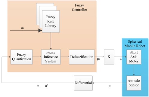
As shown in Fig. 3, αt is target torque, α is declination angle about x-axis and α' is declination angular velocity about x-axis. u0 is output of fuzzy controller, k is parameter. u is output current from short axis motor:
After uniform quantization of α and α' which collected by sensor, we can get fuzzy segmentation as shown in Fig. 4 which are divided into seven parts called NL, NM, NS, ZE, PS, PM, PL which represent –3, –2, –1, 0, 1, 2, 3 by number. The range of α is between –45 degrees and 45 degrees. The range of α' is between –450 degrees and 450 degrees, and we took trigonometric function as membership function.
The formula below is expression of membership function:
where μi, μi+1, μj and μj+1 are memberships corresponding to α and α', i, i+1, j and j+1 are fuzzy sets. Then we can establish a two-dimensional fuzzy rule table according to experimental formula as shown in Table 1.
Fig. 4Diagram of fuzzy segmentation
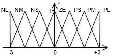
Table 1General position fuzzy rule table R
α | α' | ||||||
NL | NM | NS | ZE | PS | PM | PL | |
NL | 4 | 4 | 4 | 3 | 2 | 1 | 0 |
NM | 4 | 4 | 3 | 2 | 1 | 0 | 1 |
NS | 4 | 3 | 2 | 1 | 2 | 1 | 2 |
ZE | 3 | 2 | 1 | 0 | –1 | –2 | –3 |
PS | 2 | 1 | 0 | –1 | –2 | –3 | –4 |
PM | 1 | 0 | –1 | –2 | –3 | –4 | –4 |
PL | 0 | –1 | –2 | –3 | –4 | –4 | –4 |
According to rules of fuzzy deduction, we can obtain premise credibility [6, 7]:
According to fuzzy rule base, our results are Ri,j, Ri+1,j, Ri,j+1 and Ri+1,j+1.
So the total credibility of fuzzy system is:
μa=max{min(ωi,j,Ri,j),min(ωi+1,j,Ri+1,j),min(ωi,j+1,Ri,j+1),min(ωi+1,j+1,Ri+1,j+1)}.
Finally, we made a defuzzification to above formula and took use of center of gravity, then we can obtain the output of fuzzy control, if the calculated results of μa included ω1, ω2,…, ωn, R1, R2,…, Rn, that n represents 1, 2, …, then we can get the output:
where u0 is the output of fuzzy control system. We can control the output torque of declination angle by making use of u=k∙u0. We only considered the situation that the declination angle is zero as balance position, relevant fuzzy rule table need to be changed if the declination angle has a value.
3. The target declination angle extension of robot
In Fig. 3, we didn’t bring the target declination angle into input, because we took two-dimensional fuzzy rule table for its convenient setup. On the other hand, it is unpractical to list fuzzy rule table for every target position. In this research, the accuracy of target output torque does not need to be very high, so we took an approximate method to cover the value range of the declination angle.
Table 1 can be the fuzzy rule table without declination, but if the shell of robot is smooth which means target declination angle has no effect on dynamical model, then we can get:
where αIn is the input of declination angle of fuzzy algorithm, α0 is the actual declination angle collected from sensor, αt is target declination angle. After processing by formula, we put the declination angle into fuzzy algorithm and can get the short axis output current, which apply to this target declination angle.
When applying this method to spherical mobile robot, there are three different situations:
1) If the position of robot were nearly vertical (α≤±5°), the spherical mobile robot would be hard to return to balance position and be uncontrollable.
2) If ±5°≤α≤±25°, the control effect is favorable,
3) If α≥±25°, the robot would not keep stable at balance position.
The irregular shell is the reason of situation 1, this paper would propose control program for it. For situation 3, the reason is the imbalance of internal weight according to our observation, so the motor can add an additional torque to balance it.
For situation 3, first we got the value of balance torque of several special points through experiment, then we took approximate method to obtain balance torque of each position. The output current of motor is shown in Table 2.
Table 2Balance angle
Motor output of balance position / mA | 2000 | 2500 | 3000 | –2000 | –2500 | –3000 |
Declination angle | –26° | –34° | –39° | 29° | 39° | 47° |
We can obtain final output current Iout by Table 2:
where Iblur is the output of fuzzy control algorithm from calculation, I0 is the output current of motor at balance position. In order to verify the feasibility of this method, we conducted an experiment, and the experimental result is favorable. This paper used approximate method to extend the fuzzy thought, achieved the declination of robot and laid a good foundation for robot’s circular motion.
3.1. Zero degree declination angle fuzzy controller
While using fuzzy algorithm to control robot, we found that the bigger the declination angle is, the better the performance is. But, if we tried to keep robot balance at zero degree position, problem was emerged. After our careful analysis, the major factor of difficult balance is the irregular shape of robot.
It is precisely because of the particular shape that if we tried to make robot keep balance at vertical position, robot could finish balance automatically between ±5 degrees, but if external force made the declination angle bigger than ±5 degrees, robot would tilt to one side immediately and finally keep balance between ±10 degrees. It is because the shape of robot is similar to ellipse. So, the result stated that the fuzzy rule table which was made by experience should be improved.
With countless modification of fuzzy rule table, the fuzzy controller could keep balance at zero degree position which ensured the smooth use of standstill or linear motion.
After many times of experiments and observation, we obtained fuzzy rule table as shown in Fig. 3, the output would be high when the declination angle is NS or PS. The reason is that the declination angle could easily come to balance point when it was between ±10°, that is to say, only the short axis motor provided bigger torque can make the robot turn to zero degree angle continually. So, in order to make robot generate high torque, the output at NS and PS of fuzzy rule table should be high too.
Table 30° declination angle fuzzy rule table
α | α' | ||||||
NL | NM | NS | ZE | PS | PM | PL | |
NL | 4 | 4 | 4 | 3 | 2 | 1 | 0 |
NM | 4 | 4 | 3 | 2 | 2 | 0 | 1 |
NS | 4 | 3 | 2 | 2 | 2 | 1 | 0 |
ZE | 3 | 2 | 1 | 0 | –1 | –2 | –3 |
PS | 0 | –1 | –2 | –2 | –2 | –3 | –4 |
PM | 1 | 0 | –2 | –2 | –3 | –4 | –4 |
PL | 0 | –1 | –2 | –3 | –4 | –4 | –4 |
Then we can make use of the same method of section 2.2, and we can get the output current u of short axis motor after fuzzy quantization, fuzzy inference and center of mass. But this fuzzy algorithm still cannot well performance the property of flat joint of shell. The output close to zero position was influenced by the high output at NS and PS, so the shaking and bad stability was emerged inevitably, we developed dead area rule for this:
So far, the fuzzy controller can control the robot return to its zero degree position on the flat ground. And it made a preparation for the control of linear motion.
3.2. Self-adaption declination angle control based reference model
We have illustrated the fuzzy control of declination angle of SMR before. But in practice, because the fuzzy rule table is mainly rely on the subjective perception, the control effect is not ideal enough. The stability needs to be improved, and there is also some place to advance in the adaptability to environment due to the structure of robot. It should be optimized. For that, we introduced a kind of self-adapted algorithm to improve the fuzzy controller what we already have.
The self-adaption ability defined that robot should adjust parameter in real time. To this algorithm, the parameters include fuzzy rule table, fuzzy quantization coefficient and output coefficient (as shown in Fig. 4), we made adapt itself here to advance the performance of system for the convenience. In order to improve the algorithm, the shell is almost smooth except the joint and can obtain good control property by the simple fuzzy controller. So we can adjust coefficient to adapt fuzzy controller and optimize controller finally.
The writer have already done dynamical model despite there is a little error with actual model. The fuzzy controller in section 2.2 can well control the dynamical model, so we chose it as reference model to make the dynamical performance of robot tend to reference model by adjusting . So we can achieve great control effect through fuzzy controller.
The diagram of self-adaption algorithm is shown in Fig. 5, and we took gratitude reduction as study algorithm. In order to make dynamical property of robot tend to reference model at any position, the value of should be relative to declination angle of shell. If we took similar method, which selected several value of to represent function , the resolution is too small to meet the requirement. But if the resolution is too large, it would not meet the requirement because the lack of generalization.
We decided to adopt the method of fuzzy to meet control requirement. First, we made fuzzy quantization to as shown in Fig. 2, the fuzzy rule table of is shown in Fig. 4.
Table 4Fuzzy rule table Rk
NL | NM | NS | ZE | PS | PM | PL | |
2000 | 2000 | 2000 | 2000 | 2000 | 2000 | 2000 |
Fig. 5Control diagram of self-adaption algorithm
We could make the output of obtain generalization and convenient of study. From gradient study algorithm, we can get:
where is membership, is study efficiency which is 100 here, is the output of reference model. In conclusion, we can use the algorithm to adjust by adjust fuzzy rule table in real time. But for reference model, fuzzy controller can obtain favorable effect, and own the resistance to the disturbance of outside world. The self-adaption algorithm can greatly achieve large-size SMR control which has been proven by our experiment.
4. The standstill experiment of control algorithm for spherical mobile robot
4.1. The experimental analysis of the declination angle extension
In order to verify that the algorithm can improve the performance of robot, we adopted a standstill control method that robot stand still which is relatively easy. The main purpose of this experiment is verifying that robot can keep balance by the effect of balance torque at the time when is bigger than degrees. The parameter of robot is shown in Table 5.
Table 5The parameter of SMR’s declination angle extension
Item | Value |
Radius of shell | 500 mm |
Total mass | 50 kg |
Mass of balance weight | 10 kg |
Pendulum length | 350 mm |
Maximum torque of motor | 13 Nm |
Frequency of data collection | 10 Hz |
Running frequency of control algorithm | <50 Hz |
Original position | 0° |
Target position | 34° |
In the experiment, we took 0 degree as original position, took 34 degrees as target position. According to Table 2, the output current of motor at balance position is 2500 mA, the experimental result is shown in Figs. 6 and 7.
Fig. 6The declination angle
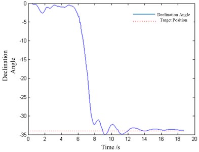
Fig. 7The motor output
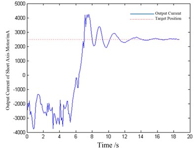
According to the experimental results, with the adjustment of balance torque, the output of fuzzy control algorithm can achieve great control effect at any declination angle.
4.2. Experiment analysis of robot’s optimized algorithm
In this experiment, we mainly tested the balance property of robot at zero degree before and after optimize. The parameter of robot is shown in Table 6.
Table 6The parameter of SMR’s declination angle extension
Item | Value |
Radius of shell | 500 mm |
Total mass | 50 kg |
Mass of balance weight | 10 kg |
Pendulum length | 350 mm |
Maximum torque of motor | 13 Nm |
Frequency of data collection | 10 Hz |
Running frequency of control algorithm | <50 Hz |
Original position | 30° |
Target position | 0° |
Fig. 8The declination angle
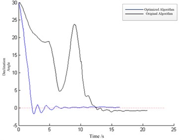
Fig. 9Output current
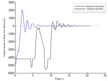
The angle of original position was set as 30°, and the angle of target position was set as 0°. The reason that we took 0° as target position is that robot’s position is regular out of 5° and basically abide the dynamical model of robot, the difference is also minor compared to reference model, so the experiment benefited us much in verifying the effectiveness of this optimized method.
The experimental result is shown in Figs. 8 and 9. First, we compelled robot deflecting several times to make robot study optimized algorithm, then we released it from original position, when robot returned to its zero degree, we obtained the data. Figs. 8 and 9 is the experimental results of declination angle and output current.
After analyzed the data, we can get that the optimized algorithm resolved the insufficiency of output current which caused by the irregular shell, and this problem is hard to be resolved by changing fuzzy rule table. It’s because the joint of robot is also irregular, so the performance of control is bad, but self-adaption can guarantee the controllability of robot in a certain extent.
5. Liner and curved motion
We have discussed the standstill control of the robot in detail above, and the linear motion control of the robot can also use the fuzzy control method. The linear motion is the simplest motion state of the spherical robot. We can firstly keep the declination angle at 0 degree, secondly export the driving torque about the -axis, the robot can finally accomplish linear rotation. The fuzzy control we have applied can help the robot to keep the linear path approximately and to prevent from the overturn, but if we’d like to reach higher precision of linear motion, there is still much work to do, which is about path measurement and correction.
We did some experiments for linear motion, the experimental result is shown in Fig. 10. The red curve represents the rotated angle of long axis, the blue curve represents the rotated angle of short axis. According to the picture, we can know that the waveform of long axis’s rotated angle is similar with sine wave.
Fig. 10The robot’s rotated angle of linear motion
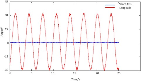
Fig. 11The path chart of curved motion
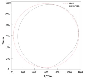
The simulated result of curved motion is shown in Fig. 11. The robot set out from one point, and then drove by two motors, finally came back to the starting point. But in the practical experiment, we found that because of the friction of ground, deformation of shell and the error of control algorithm, the robot can’t come back to the starting point precisely. So this is also our future work to minimize the error between robot and the starting point.
The curved motion is the most common and important motion of the spherical robot. In the structure of this kind of robot, turning rate is controlled by the change of declination angle which will be turned to a certain direction, and a closed-loop control of the robot direction and declination angle is necessary. In this kind of motion state, fuzzy control method as described above just give out a feasible and basic control method of the robot.
In summary, basically linear and curved motion can be accomplished through the fuzzy control above, not only the precise and applicable motion control need the method to control the declination angle, but also it need more research and work about the path and directional control.
6. Conclusions
In this paper, we introduced fuzzy control to implement the control of deflection movement of robot due to the characteristic of robot. After concretely analyzed the influence that its structure and production may create, we designed adaptive fuzzy rule library. And aiming at the situation that robot may be effected easily, we adopted a coefficient algorithm based reference model to achieve the optimization and compensate disturbance from outside world. Finally we made a simulation and an experiment for linear motion and circular motion based on the control algorithm. The experiment proved that fuzzy control is competent to the control problem of robot. We can know from the experiment that the controllability and stability would dramatically increase after using reference model to optimize the fuzzy control algorithm.
References
-
Kaznov V., Seeman M. Outdoor navigation with a spherical amphibious robot. International Conference on Intelligent Robots and Systems, 2010, p. 5113-5118.
-
Ogata K., Yang Y. Modern Control Engineering. Upper Saddle River, NJ, USA, Prentice Hall, 1990.
-
Haykin S. S., Haykin S. S., Haykin S. S., et al. Neural Networks And Learning Machines. Prentice Hall, 2009.
-
Kraft L. G., Campagna D. P. A comparison between CMAC neural network control and two traditional adaptive control systems. Control Systems Magazine, Vol. 10, Issue 3, 1990, p. 36-43.
-
Zhang Nai-Xiao, Belschner C. E. R. Inverted pendulum based on double closed-loop fuzzy control. Control and Decision, Vol. 11, Issue 1, 1996, p. 85-88.
-
Liu Jin-Kun Intelligent Control. Publishing House of Electronics Industry, 2009.
-
Sun Zeng-Qi, Zhang Xiao-Xiang The Theory and Technology of Intelligent Control. Tsinghua University Press, 1997.
-
Kovačić Z., Bogdan S., Reichenbach T. Nonlinear position control by using multiple position dependent self-organizing fuzzy logic controllers. 6th IFAC Symposium on Robot Control, 2000.
-
Layne J. R., Passino K. M. Fuzzy model reference learning control. First IEEE Conference on Control Applications, 1992, p. 686-691.
-
Yue M., LiuB. Y. Design of adaptive sliding mode control for spherical robot based on MR fluid actuator. Journal of Vibroengineering, Vol. 14, Issue 1, 2012, p. 196-204.
About this article
This research was jointly sponsored by the Shanghai Municipal Education Commission and State Lead Academic Discipline Fund (Project No. 12ZL1410700), the National High-tech R&D Program of China (863 Program, Grant No. 2011AA040202) and the China Scholarship Council Fund (File No. 201208310055), which are greatly appreciated by the authors.
