Abstract
A detailed orthogonal design of a vane-type vortex generator (VG) was performed by varying angles of attack and geometrics including delta, cropped-delta, rectangle and trapezium configurations. Influences of different shapes, angles of attack and geometric parameters of VG on the wake vortex were analysed. Results show that the vortex strength and drag of the triangle VG are minimal while the vortex strength and drag of the rectangular is maximal. The rectangular configuration has the highest wake vortex core orientation, while subsequently followed by cropped-delta, trapezoid and triangle layouts. Due to the fact that mounted height and angle of attack of VG have a significant influence on the wake vortex, a coherent computational campaign was conducted on a Unmanned Aerial Vehicle (UAV) equipped with a VG in front of the top-mounted subsonic intake. The aerodynamic interference from VG are numerically examined when the UAV operated at high angles of attack. Research revealed the development of forebody vortex and the effectiveness of flow control by vortex generator on the performance of the intake. Comparing to cases without VG, the distortion index |DC60| of the intake decreased 7.1 % and 5.9 % respectively at the angle of slip β=2° and 4°, while the total pressure recovery remains almost the same.
1. Introduction
Intake as a crucial part of an aircraft has to remain aerodynamically compatible with the engine within the flight envelope [1]. Poor performance of intake would result in compressor stall or engine surge, which can cause vibration and even fracture of compressor blades. Total pressure recovery and distortion at the interface between intake and engine are the two main factors which predominately influence the intake/engine compatibility. In UAV design, top-mounted intakes are usually employed due to their stealth capability, structural integration, less foreign object damage [2], etc. However, the top-mounted layout suffers from low total pressure recovery and terrible distortion of the inlet at high body angle regime since the majority of the intake are submerged in the boundary layer and vortex of the forebody.
Vortex generators as one of the passive flow control methods, are normally used in the internal flow control of intakes and boundary layer control of wings. Studies about vortex generator can be widely found in literatures. Reichert [3] and Allan [4] used vortex generators in an S-shaped subsonic intake diffusers to decrease the distortion at the outlet. Chen [5] revealed that vortex generators can decrease the total pressure recovery when they were used to eliminate the separation region of the diffuser. Anderson [6, 7] showed that VG installations can be designed using CFD and optimization procedures. Tsze [8] simulated the flowfield around the wing with vortex generators installed at different positions and angles, and investigated the variation of lift and drag of V-22 caused by VGs. Broadly and Garry [9] experimentally investigated the effectiveness of vortex generators’ orientation on highly swept wings in wind tunnel, they obtained the optimum height and angular deflection of VGs. However, VGs are mostly used in pairs or in array [10-12], which are difficult to predict the complex flows and interactions of vortices.
Although the research and applications of VGs have been tremendously conducted, studies about the parametric shape design of VGs were rarely documented in literatures. Recently, most designs of VGs are empirically based. Furthermore, though VGs have been widely used in intake flow control and wing flow control, the application of VGs on forebody of aircraft and the influence on the performance of intakes are seldom mentioned.
In this study, an orthogonal method on the parametric shape design of VGs is presented. Later on, a VG had been successfully designed and optimized by the presented methodology. The optimized VG was installed on the forebody of a UAV to evaluate its aerodynamic performance in reducing the adverse impact of forebody vortex. Eventually, the flowfields of the UAV equipped with VG were numerically simulated and the effects of vortex generator on the performance of top-mounted intake were discussed.
2. Methodology and validation
Numerical simulation was performed in the commercial software FLUENT V6.3 solving the Reynolds-Averaged Navier-Stokes equations. Invisid and viscous fluxes are spatially discretised by Roe and second order centered difference, respectively. Low Upper Symmetric Gauss-Seidual (LU-SGS) is employed for temporal discretisation in the implicit iterations. Due to the relative high Reynolds number and complex flow behavior, kω SST turbulent model is employed [13].
To validate the physical accuracy of the present numerical method, computational results was compared with the experimental data from Yao et al. [14]. The schematic diagram of the vortex generator installed on a flat plate is depicted in Fig. 1(a), parameters were directly extracted from [14]. The dimensions of the computational domain and VG are defined in Table 1.
Table 1Dimensions of VG
Dimensions | (mm) |
L1 | 2250 |
L | 3820 |
D | 210 |
H | 210 |
h | 35 |
l | 70 |
Fig. 1(b) shows the trapezoid VG used in the computation, where, h and l are the height and length of the VG, respectively. α is the side angle, θ depicts the attack angle respect to the upstream, the boundary layer thickness (δ) at the device location is 30 mm. The VG has a thickness of 0.4 mm with device angle of attack of 16°.
Fig. 1The computational domain and schematic diagram of a vortex generator
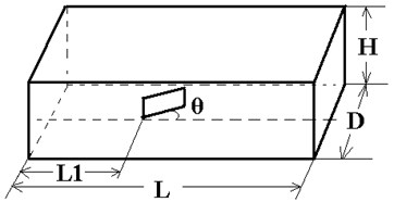
a) The computational domain
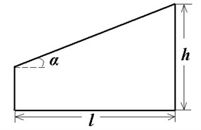
b) Schematic diagram
Fig. 2 shows the three dimensional structured mesh of the vortex generator. The mesh was refined near the leading and trailing edges of the VG, and the distance along the flow direction was set to 1 mm. The first grid distance of the boundary layer is defined as 10-5 of the characteristic length. The total number of nodes achieves at around 2 million. Boundary conditions included pressure far-field and wall.
Fig. 2Structured mesh of vortex generator
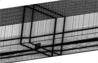
Table 2Measuring stations in the cross-flow planes
Station No. | Δx (mm) | Δx/h |
1 | 35.34 | 1.0 |
2 | 121.84 | 3.5 |
3 | 764.53 | 22.0 |
Three measuring stations were listed in Table 2, where Δx represents the distance from the trailing edge of the VG. The present computational predictions of velocity contours were compared with experimental results at the three stations as shown in Fig. 3. The comparison showed a good agreement between computational results and experimental data, which proved that the computational method is feasible and reliable for predicting the flow behavior of VGs.
Fig. 3Comparison of mean velocity contours at 3 stations downstream of VG for θ = 16°
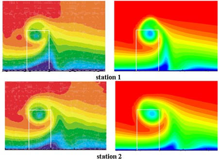
a) Experimental results [14]
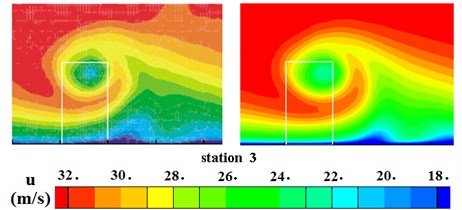
b) Computational results
3. Comparison of vane geometries
In order to evaluate the vane geometry effects on the characteristics of VGs, computations are conducted on four different shapes: delta, cropped-delta, rectangle and trapezium, as shown in Fig. 4. All the VGs are of the same height and thickness, which are set at 35 mm, 75 mm and 0.4 mm, respectively. A relative higher angle of attack is defined at 16°.
Fig. 4Vane geometry of VGs
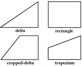
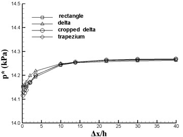
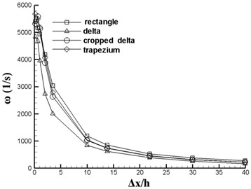
Fig. 5 plots the vortex center (or core) location, total pressure and vorticity ω as functions of downstream location (Δx). One can determine the vortex path in both lateral (y) and vertical (z) directions, as shown in Figs. 5(a) and (b) for the four VGs. All coordinates are nondimensionalized by the h of VG. When Δx/h>10, rectangular vane has the maximum y while the cropped-deltaic vane has the minimum y. It can be shown from Fig. 5(b) that the heights of wake vortex core are listed as z (triangle) <z (trapezoid) <z (cropped-delta) <z (rectangular). Further downstream, the total pressure and vorticity of the four VGs are almost identical (Fig. 5(c) and (d)).
Fig. 5Vortex comparison of VGs
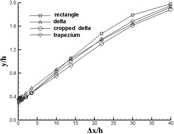
a) Vortex paths in lateral (y) direction
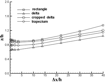
b) Vortex paths in vertical (z) direction
c) Total pressure of vortex center
d) Vorticity of vortex center
The pressure drag, friction drag and total drag of each VG are listed in Table 3. The friction drags of the four configurations almost stay same, while the pressure drags differs significantly from each other. Among the four VGs, rectangular vane has the maximum drag while deltaic vane gives the best drag performance. Similar results have been revealed by Ni [15], he mentioned that deltaic vane has the lowest vortex strength because its leading edge is close to the wall surface and most of its surface is submerged in the boundary layer when the vehicles fly at a slow velocity.
Table 3Drag of VGs
Vane geometry | Rectangle | Delta | Cropped-Delta | Trapezium |
Pressure drag (N) | 0.0486 | 0.0208 | 0.0358 | 0.0316 |
Friction drag (N) | 0.0020 | 0.0022 | 0.0029 | 0.0022 |
Total drag (N) | 0.0506 | 0.0231 | 0.0387 | 0.0338 |
Rectangular vane and trapezoidal vane have a stronger vortex, while their drags are also higher. Rectangular and trapezoidal vanes have almost the same vortex strength, while the drag of trapezoidal vane is lower than that of rectangular vane.
4. Orthogonal design of VGs
Orthogonal design is an important multi-factor design method, which is used to analyse the comparative effectiveness of multiple variables [16]. This method is very suitable for the design of VGs.
Due to the low drag performance, Trapezoidal vane was selected for the following design and analysis. The aerodynamic characteristics of trapezoidal vane are related to the height, the length, the attack angle respect to the upstream, angle of side edge and the thickness. In this study, the height of VG is defined as h=0.2 δ1.0 δ, where δ is the boundary layer thickness at the device location. The length of VG l is set at 2h. The inflow angle θ and side edge angle α are prescribed as 10°-30° and 5°-25°, respectively, with an increment of 5. The VG thickness d=0.4-4 mm.
The factors for the orthogonal design are h/δ, θ, α and d/δ. The values of each factor at different levels are listed in Table 4.
Table 4Orthogonal array
Factors | h/δ | α (°) | θ (°) | d/δ |
Levels | 0.2 | 5 | 10 | 0.0133 |
0.4 | 10 | 15 | 0.0433 | |
0.6 | 15 | 20 | 0.0733 | |
0.8 | 20 | 25 | 0.1033 | |
1.0 | 25 | 30 | 0.1333 |
Taguchi L25 orthogonal design is used and the number of observations is 25. Numerical simulations were conducted to investigate the effect of each factor on the performance of VG.
The measuring positions in the cross-flow planes of VGs’ numerical simulation results are depicted in Table 5.
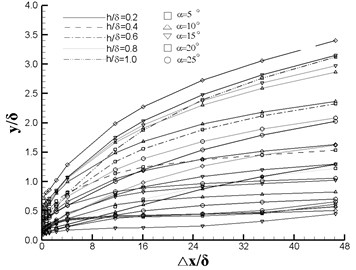
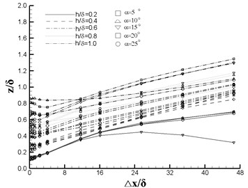
Fig. 6 shows the vortex center location, total pressure and vorticity ω as functions of downstream location (Δ x/δ). It can be seen from Fig. 6(a) that y/δ increases with the increasing Δ x/δ and h/δ, and the disparity increases along with the flow direction. The effect of z/δ has the same trend as y/δ while the maximal offset value 1.4 (Fig. 6(b)). From Fig. 6(c), it can be seen that the total pressure varies slightly after Δ x/δ>16. In Fig. 6(d), the magnitude of vorticity ω behaves a sharp decrease at the first four monitoring positions and approach 0 afterwards.
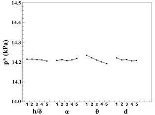
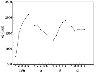
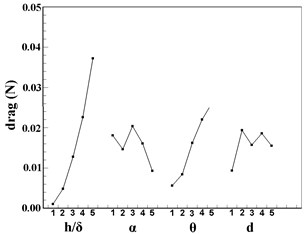
Fig. 7 plots the tendency chart of orthogonal design factors based on the data of station 5. For y/δ, impact factors are in the sequence of θ, h/δ, α, d/δ, among which α and d have almost the same effect on y/δ. It can be concluded from Fig. 7(b) that the z/δ is more significantly affected by y/δ than the other three factors. The total pressure p* does not change a lot with the factors except a relative larger variation caused by θ, see in Fig. 7(c). For ω, impact factors are in the sequence of h/δ, θ, α, d/δ, and the effect of d/δ is neglectable. For the drag, impact factors are in the sequence of h/δ, θ, α, d/δ, and α and d/δ are of the same importance. In conclusion, in VG design, the height h and the angle of attack θ are the two predominate factors which can influence the performance of the VG.
Table 5Measuring stations in the cross-flow planes of VGs
Station no. | Δx (mm) | Δx/δ |
1 | 6.78 | 0.2260 |
2 | 21.24 | 0.7080 |
3 | 35.34 | 1.1780 |
4 | 69.61 | 2.3203 |
5 | 121.84 | 4.0613 |
6 | 349.25 | 11.6417 |
7 | 482.71 | 16.0903 |
8 | 764.53 | 25.4843 |
9 | 1048 | 34.9333 |
10 | 1397 | 46.5667 |
Fig. 6Vortex comparison of orthogonal design
a) Vortex paths in lateral (y) direction
b) Vortex paths in vertical (z) direction
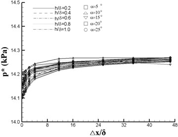
c) Total pressure of vortex center
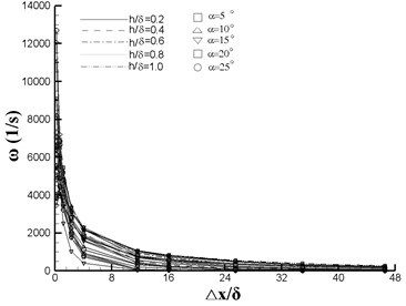
d) Vorticity of vortex center
5. Application on UAV
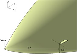
In order to assess the influence of the VGs on the aerodynamic performance of flyers. An UAV with a top mounted intake are established in CATIA. A trapezoidal vane was mounted on the forebody of the UAV, see in Fig. 8. The angle of attack α is defined at a relative high value of 30°. Inflow Mach number M∞=0.2.
Fig. 7Tendency chart of VGs: a) y/δ; b) z/δ; c) p*; d) ω; e) drag
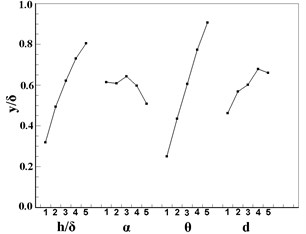
a)
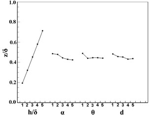
b)
c)
d)
e)
Fig. 8Position of VG on the UAV fuselage forebody and the slice sections
a) Oblique view
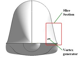
b) Front view
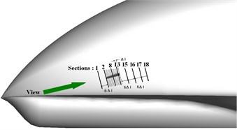
c) Left side view
18 measuring sections are perpendicular to the longitudinal direction of the vane. Section 1 is located in front of the vane, section 2 to 14 are located on the vane regime with an equal space Δl=l/12, while all other sections have a spacing of 6Δl.
After comparing the numerical simulation flowfields of a dozen cases with varied Δx, Δy, h, and bluntness, parameters of the trapezoidal vane are set as: h=60 mm, l=120 mm, α=10°, d=8 mm,θ=30°.
The distance between the vertex and the VG is Δx=62 mm. Δy=8.28 mm Leading edge bluntness of the vane is not necessary.
Fig. 9(a) draws vortex streamlines generated from the nose of the fuselage, note that only the left part of the UAV is displayed due to the symmetric geometry. It is obvious to see that the partial vortex is sucked into the intake and result in the total pressure recovery distortion at the upper part of the outlet (Fig. 9(b)).
Fig. 9Numerical simulation result at M∞=0.2, α= 30°
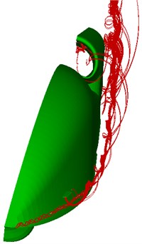
a) Vortex streamlines of the fuselage (half)
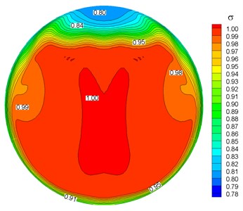
b) Total pressure recovery distribution of the outlet
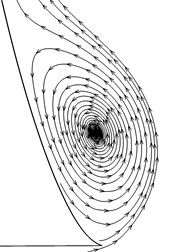
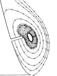
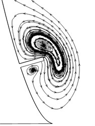
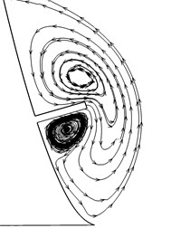
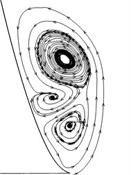
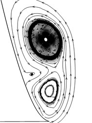
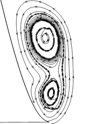
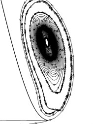
To obtain a detail flow information around the VG, streamlines of some characteristic sections are near-viewed plotted in Fig. 10. A stable anticlockwise vortex is generated at section 1, and squeezed outward at the very front of the VG, i.e. Section 2. Then the vortex is pushed downward and meets with a VG induced vortex (section 8), which is counter-rotating and becomes stronger downstream (section 13). The forebody vortex mixes with the induced vortex and finally turns into one vortex. The vortex strength is weakened and the vortex center is moved downward (section 15 to section 18), where is far away from the entrance of the intake.
The performance of the intake outlet are quantized conducted to assess the benefits of the VG based on the slip angle.
When angle of slip is considered, only the vortex from the windward of the forebody will be sucked into the intake. The formation and dissipation of the vortex is very similar to that in Fig. 10. Table 6 shows the intake performance with and withour VG at the condition of angle of slip β=2° and 4° respectively. Comparing to cases without VG, the distortion index |DC60| decreased 7.1 % and 5.9 %, respectively, while the total pressure recovery remains almost the same.
Table 6Performaces of the intake with sideslip
Total pressure recovery σ | Distortion index |DC60| | |
β=2°, without VG | 0.9820 | 0.4087 |
β=2°, with VG | 0.9816 | 0.3743 |
, without VG | 0.9816 | 0.4023 |
, with VG | 0.9813 | 0.3785 |
Fig. 10Streamlines on each section
Section 1
Section 2
Section 8
Section 13
Section 15
Section 16
Section 17
Section 18
6. Conclusions
The parametric and geometry design method of VGs were presented using orthogonal design method by numerical simulation. The flowfields of a UAV equipped with VG on forebody fuselage were analysed and the effects of vortex generator on the performance of top-mounted intake were discussed. Results are summarized as follows:
(1) Deltaic vane has the lowest vortex strength. Rectangular vane has the maximal vortex strength and drag. Trapezoidal vane has almost the same vortex strength as the rectangular vane, while the drag of trapezoidal vane is lower than that of rectangular vane.
(2) The most important two design factors are the height and angle of attack of vortex generator, which play great roles on the influence of wake vortex.
(3) Investigations performed by numerical simulation on a subsonic top-mounted intake of Unmanned Aerial Vehicle with vortex generator installed on the fuselage forebody at angle of attack show that properly designed vortex generator can affect the forebody vortex and reduce the distortion of the intake.
(4) Comparing to cases without VG, the distortion index of the intake decreased 7.1 % and 5.9 % respectively at the condition of angle of slip and , while the total pressure recovery remains almost the same.
References
-
Seddon J., Goldsmith E. L. Intake aerodynamics. Collins Professional and Technical Books, London, 1985.
-
Vooren A., Kewenter H., Edefur H. Top mounted air inlet for supersonic and transonic military aircraft. Royal Institute of Technology Department of Aeronautics, 2001,
-
http://www.ave.kth.se/education/msc/courses/4E1232/2001/aero2/TMI_Report.pdf
-
Reichert B. A., Wendt B. J. An experimental investigation of s-duct flow control using arrays of low-profile vortex generators. AIAA 93-0018, 1993.
-
Allan B. G., Owens L. R. Numerical modeling of flow control in a boundary-layer-ingesting offset intake diffuser at transonic Mach numbers. AIAA 2006-845, 2006.
-
Chen X., Jiang P. Application of submerged vortex generators for separation control of a subsonic diffuser. Journal of Aerospace Power, Vol. 7, Issue 3, 1992, p. 226-290, (in Chinese).
-
Anderson B. H., Gibb J. Study on vortex generator flow control for the management of inlet distortion. Journal of Propulsion and Power, Vol. 9, Issue 3, 1993, p. 422-430.
-
Anderson B. H., Gibb J. Vortex generator installation studies on steady state and dynamic distortion. AIAA 96-3279, 1996.
-
Tai T. C. Effect of micro-vortex generators on V-22 aircraft forward-flight aerodynamics. AIAA 2002-0553, 2002.
-
Broadly I., Garry K. P. Effectiveness of vortex generator position and orientation on highly swept wings. AIAA 97-2319, 1997.
-
Stillfried F., Wallin S., Johansson A. V. An improved passive vortex generator model for flow separation control. AIAA 2010-5091, 2010.
-
Dudek J. C. Modeling vortex generators in the wind-us code. NASA/TM-2010-216744, 2010.
-
Gissen A. N., Vukasinovic B., McMillan M. L., Glezer A. Distortion management in a BLI inlet diffuser using synthetic-jet hybrid flow control. AIAA 2011-35, 2011.
-
Allan B. G., Yao C., Lin J. C. Numerical simulations of vortex generator vanes and jets on a flat plate. AIAA 2002-3160, 2002.
-
Yao C., Lin J. C., Allan B. G. Flow-field measurement of device-induced embedded streamwise vortex on a flat plate. AIAA 2002-3162, 2002.
-
Ni Y. Development of the vortex-generator and study on the effect of vortex-generator on boundary layer. Acta Aerodynamica Sinica, Vol. 13, 1995, p. 110-115, (in Chinese).
-
Yang D. Design and analysis of experiments. China Agricultural Press, Beijing, 2002, (in Chinese).
About this article
This work was sponsored by the NUAA Research Funding (Project No. NP2011008). The finical support by China Scholarship Council (CSC) is gratefully acknowledged.
