Abstract
This research suggests employing electrode segmentation in order to avoid charge cancellation in the piezoelectric layers of harvester, which occurs, if strain nodes of vibrating harvester are covered by continuous electrodes. Two types of piezoelectric energy harvester prototypes were produced from piezoelectric plate, epoxy bonded to stainless steel substrate for experimental investigations. The first (reference) harvester prototype posses no electrode segmentation, while electrodes covering piezoelectric material of second harvester were segmented. Segmentation of the second harvester was configured for its operation at the second resonant frequency – i.e., performed so, that the electrodes of piezoelectric layer are not covering strain node of the second vibration mode. Experimental results revealed that segmented harvester prototype posses efficiency advantage as compared to the non-segmented counterpart – adding voltages, generated at each segment would result from 16 % to 60 % increase of maximum generated voltage. Also conception, that using stopper, placed at appropriate position, energy harvesting process could be stabilized, i.e. bandwidth of operating frequency could be increased.
1. Introduction
Energy harvesting from environment for wireless sensor networks (WSNs) has been in intensive research for more than a decade, as exploitation of WSN nodes, currently powered by batteries, is very expensive due to complicated battery replacement, caused by inconvenient mounting and abundance of nodes. Thus, research community is aiming to develop a self-powered WSN nodes, which would eliminate the most costly issue of battery replacement and/or sudden failure of the node due power run-out [1].
There is a variety of energy sources in the environment, including light, thermal and kinetic energy, however harvesting of kinetic environmental energy employing piezoelectric actuators is capturing the most interest, as these harvesters possesses features of higher energy density, good dynamic response, self-contained power generation and relative ease of integration as well as production employing MEMS technologies. Despite the intense research, piezoelectric energy harvesters are still not widely used in practical applications since current configurations of harvesters do not perform efficiently in real environments.
Various techniques and methods are used to improve piezoelectric energy harvesters’ efficiency. They are usually classified [2] into a few main strategies, aiming for (a) optimal harvester placement (optimal locations of actuators are searched for predetermined structures); (b) optimal structural design of the harvester (structure is optimally designed for one or more predetermined parameters); (c) optimal configuration of connect electronics (connected electric circuit is designed to harvester maximum power), or even combinations of (a), (b) and/or (c) are employed (e.g., simultaneous/in sequence optimization of actuator location and structural parameters). Following the above classification, this research concerns structural design optimization of the harvester, as it suggests employing segmentation of harvester electrodes in order to increase its output voltage.
Classical vibration theory suggests that higher vibration modes of the cantilever beam have strain nodes, where the dynamic strain distribution changes sign. If these strain nodes are covered by continuous electrodes, cancellation of electric outputs occurs, resulting in overall harvested energy reduction [3]. Thus, developed harvester prototype possess electrode segmentation configured for the transducer operating at the second resonant frequency, i.e., segmentation is performed so that the electrodes of piezoelectric material are not covering strain node of the second vibration mode. Its electrical outputs are experimentally measured and compared to the performance of harvester prototype, which poses no electrode segmentation.
Paper [4] reports on numerical modelling and simulation of a generalized contact-type MEMS device having large potential in various micro-sensor/actuator applications, which are currently limited because of detrimental effects of the contact bounce phenomenon that is still not fully explained and requires comprehensive treatment. The proposed 2-D finite element model encompasses cantilever microstructures operating in a vacuum and impacting on a viscoelastic support. The presented numerical analysis focuses on the first two flexural vibration modes and their influence on dynamic characteristics. Simulation results demonstrate the possibility to use first two modes and their particular points for enhancing MEMS performance and reliability through reduction of vibro-impact process duration and usage of electrodes segmentation.
In paper [5] hybrid numerical – experimental optical techniques are applied for holographic imaging and characterization of nonlinearity in micro-mechanical relays, in particular their cantilevers. The apparent simplicity of the problem is misguiding due to non-linear interaction between the cantilever and the bottom electrode. Therefore the results of optical measurements of the cantilever dynamics are inaccurate due to the shift of the fringes in time average laser holographic interferograms. Numerical modelling helps to solve non-uniqueness of the inverse problem and to validate the interpretation of the pattern of fringes.
2. Determination of harvester strain nodes
To determine preliminary location of harvester strain nodes its Finite Element model was created employing COMSOL Multiphysics software [6]. Modelled piezoelectric energy harvester (scheme of which is depicted in Fig. 1 is a cantilever beam, comprised of substrate (steel, 37 mm, 0.36 mm, width 11.05 mm) and piezoelectric material layer (T107-H4E-602, 37 mm, 0.191 mm, width 10 mm). Respective boundary conditions were set to represent electrodes (their influence on mechanic characteristics of the system is not considered due negligible thickness) on the piezoelectric material as well as clamping of the cantilever.
Fig. 1Principal geometry of the developed unimorph transducer (meshed)

Fig. 2Von Misses stress distribution for the second vibration mode of the energy harvester
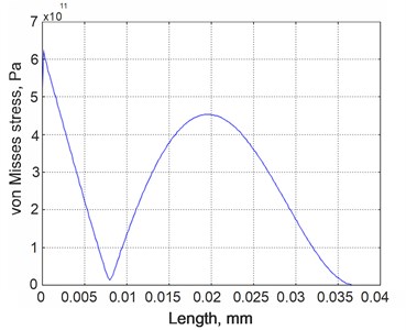
FE model was subjected to eigenfrequency analysis and location of the strain nodes was determined employing COMSOL Postprocessing function, Cross-Section Plot Parameters, Von Misses stress plots (Fig. 2). Simulation results reveal, that strain node of the second vibration mode is located 9 mm from the clamping point, thus electrode were segmented at this particular location.
3. Research objects and experimental setup
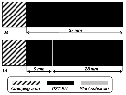
For this study purposes two prototypes of piezoelectric energy harvesters were built. They were produced from Piezo systems, Inc. T107-H4E-602 plate covered with conductive layers (cut to the desired dimension), epoxy bonded to stainless steel substrate. The first harvester prototype (Fig. 3(a)) posses no electrode segmentation while the second transducer prototype (Fig. 3(b)) possess electrode segmentation configured for the transducer operating at the second resonant frequency, i.e., segmentation is performed so that the electrodes of piezoelectric material are not covering strain node of the second vibration mode.
Fig. 3Schemes of produced transducer prototypes: a) non-segmented; b) segmented – intended for operation in 2nd vibration mode
Two experimental setups for analysis of energy harvester prototypes were used. Doppler vibrometry system was used to measure tip displacement (or velocity) of the harvester in the transverse direction. This system consists of differential laser interferometer POLYTEC OFV-512 and vibrometer controller POLYTEC OFV-5000. While non-contacting holographic measure-system PRISM (produced in USA by company HYTEC) was used in order to determine vibration forms of piezoelectric energy harvester and its response to stopper.
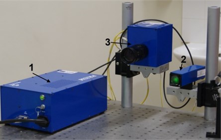
PRISM system combines all the necessary equipment for deformation and vibration measurement of most materials in a small lightweight system. The main parts of the PRISM system are presented in the Fig. 4 [7]. The PRISM system is a two beam speckle pattern interferometer (measurement sensitivity 20 nm, dynamic range – 10 m, measurement range 100 m, data acquisition rate – 30 Hz). In the study green (532 nm, 20 mV) laser is used. The laser beam, directed at the object is called the object beam, the other beam, which goes directly to the camera, is the reference beam. Laser light scattered by the object is collected by the camera and interference image is registered. Real time hologram is observed in the monitor.
Shape changes, which occur during the process, produce fringes on top of the image of the object, which are displayed on the monitor. It is necessary to make assumption that time varying displacement is along -axis, which, in the holographic arrangement is used. It is along the line of sight between object and observer. The displacement is a periodic function of time and the development is simplified if the displacement is allowed to vary only with and time, it is presumed that . If is the resting phase distribution, then the object complex amplitude at the film plane is:
where is the wavelength of the laser.
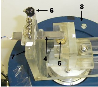
Fig. 4PRISM system: 1 – control block, 2 – illumination head of the object, 3 – video head, 4 – designed piezoelectric harvester, 5 – stopper, 6 – accelerometer, 7 – clamp, 8 – electromagnetic shaker
a)
b)
The time-average hologram is recorded with object beam and reference beam for a time , which is longer than several periods of the vibration. The reconstructed object wave has complex amplitude that is proportional to the time average of the over time , which is:
The is the zero-order Bessel function. The irradiance is calculated as following:
In this case, the image has been superimposed on a system of fringes, which correspond to the minima of the square of the zero-order Bessel function [7].
The centres of dark fringes coincide with the points of the plate, where the amplitude of vibrations is such, that the Bessel function obtains zero value. Therefore amplitude of the vibrations () in the point (centre of the th dark fringe) can be determined by the following equation:
The main part of the excitation system of energy harvester is an electromagnetic shaker, which is employed to excite piezoelectric harvester that is fixed in the custom-built clamp made of acrylic glass (Fig. 4). Single-axis miniature piezoelectric charge-mode accelerometer METRA KS-93 (with sensitivity of 0.35 mV/(m/s2)) is attached at the top of the clamp for acceleration measurements at the base of the harvester.
4. Results
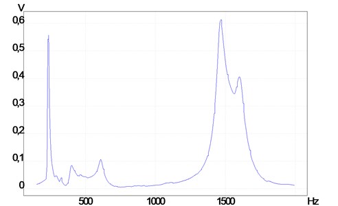
Measured frequency response of output voltage of the second segment of energy harvester is presented in the Fig. 5. It was determined, that first resonant frequency is 235 Hz, and second is 1469 Hz.
Fig. 5Measured frequency responce of output voltage of the second sector of energy harvester
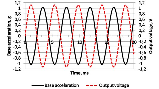
Maximum output voltage of the non-segmented energy harvester observed at the first resonant frequency is about 1.12 V (Fig. 6). However when it is excited at the second resonant frequency generated voltage decreases to 0.5 V (Fig. 7, total voltage). Therefore electrode of the energy harvester where divided to two parts in the place of the strain node as it is shown in the Fig. 3.
Fig. 6Measured time response of the base acceleration and output voltage of the non-segmented energy harvester
Measured output voltage of the first sector is 0.54 V and generated by second is 0.76 V, while energy harvester was excited by 1 g force at 1469 Hz frequency (Fig. 7). The total energy is smaller, because when energy harvester vibrates at the second resonant frequency, generated alternate voltage by these two segments has 2.44 radians phase shift. It is the reason why total energy is smaller.
Another option to improve efficiency of energy harvester is employment of stopper (Fig. 4). It is used to secure harvester from breaks and ensure the stability of processes at higher frequencies. Holograms of energy harvesterare presented in the Table 1 – firstly, without stopper, secondly with the stopper, fixed at 29 mm (nodal point of the vibration mode at 1469 Hz) and thirdly with the stopper fixed at 32 mm (nodal point of the vibration mode at 4138 Hz) from clamping point. Stopper is in full contact with energy harvester.
Fig. 7Measured time response of the first, second and total output voltage generated by segmented energy harvester
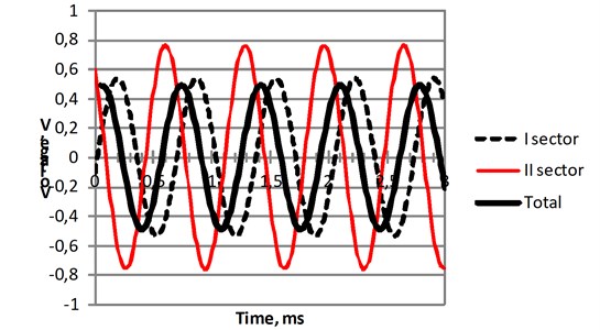
Table 1Holograms of energy harvester without stopper, and with stopper, when it is fixed at 29 mm and 32 mm from clamping point
Stopper position | Frequency | |||
235 Hz | 1469 Hz | 1663 Hz | 4138 Hz | |
No stopper |  |  |  |  |
0.78 (29 mm) |  |  |  |  |
0.87 (32 mm) |  |  |  |  |
Holograms show, that stopper, placed at 29 mm (0.78, is length of energy harvester), has no influence for the harvester vibration at 1469 Hz resonant frequency, while stopper, placed at 32 mm (0.78, is length of energy harvester), has no influence for the harvester vibration at 4138 Hz resonant frequency. Stopper, placed at 29 mm and 32 mm from clamping point, has no influence for the harvester vibration at 1663 Hz as well. It could be stated, that stopper, when it is used at low frequencies, would damp vibration amplitudes (number of black fringes in the hologram).
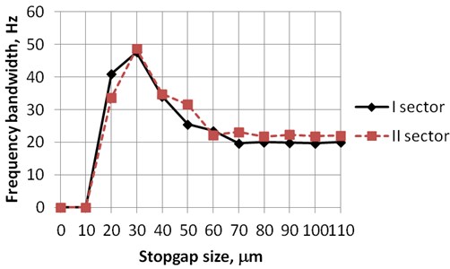
Stopper, placed at appropriate position and gap (between stopper and harvester), can stabilize the process, i.e. frequency bandwidth was increased more than two times (Fig. 8). Frequency bandwidth is frequency interval, when minimal generated voltage is not less than 0.1 V. In the future more attention will be paid to the analysis of stoppers gap and position influence for the efficiency of energy harvesting.
Fig. 8Frequency bandwidth versus stopgap size, when minimal generated voltage is not less than 0.1 V
After these researches, the main part of experimental data for created FE model was collected. Now energy harvester response to environmental vibrations could be analysed numerically. The higher flexural vibrating forms will be analysed in the future works too. It is planned to show that when stopper is placed in the nodal point of the third flexural vibrating form, energy harvester works better, because bouncing amplitude from stopper is smaller.
5. Conclusions
It is highly important to predict location of strain nodes for different configurations of piezoelectric energy harvesters in order to avoid undesired cancellation effects and harvester efficiency reduction, which occur, if strain nodes are covered with continuous electrodes. Experimental results shows, that segmentation of energy harvester electrode would result from 16 % to 60 % increase of maximum generated voltage.
Moreover, possibility to secure harvester from breaks and ensure the stability of processes at higher frequencies using stopper was shown. Stopper placed at 29 mm from clamping point with 30 m gap increases bandwidth more than two times, when generated voltage is not less than 0.1.
References
-
Saadon S., Sidek O. A review of vibration-based MEMS piezoelectric energy harvesters. Journal of Energy Con-version and Management, Vol. 52, Issue 1, 2011, p. 500-504.
-
Frecker M. I. Recent advances in optimization of smart structures and actuators. Journal of Intelligent Material Systems and Structures, Vol. 14, 2003, p. 207-216.
-
Erturk A., Tarazaga P. A., Farmer J. R., Inman D. J. Effect of strain nodes and electrode configuration on piezo-electric energy harvesting form cantilevered beams. Journal of Vibration and Acoustics, Vol. 11, 2009, p. 011010/1-11.
-
Ostasevicius V., Gaidys R., Dauksevicius R. Numerical analysis of dynamic effects of a nonlinear vibro-impact process for enhancing the reliability of contact-type MEMS devices. Sensors, Vol. 9, Issue 12, 2009, p. 10201-10216.
-
Ostasevicius V., Ragulskis M., Palevicius A., Kravcenkiene V., Janusas G. Applicability of holographic technique for analysis of non-linear dynamics of MEMS switch. Proceedings of SPIE, Smart Structures and Materials, Smart Electronics, MEMS, BioMEMS, and Nanotechnology, California, USA, Vol. 5763, 2005, p. 405-413.
-
Comsol Multiphysics – information available at website. http://www.comsol.com/products/multiphysics/.
-
Ostasevicius V., Ragulskis M., Palevicius A., Kravcenkiene V., Janusas G. Applicability of holographic technique for analysis of non-linear dynamics of MEMS switch. Proceedings of the Society of Photo-Optical Instrumentation Engineers, Vol. 5763, 2005, p. 405-413.
About this article
This research was funded by a grant (No. MIP-060/2012) from the Research Council of Lithuania.
