Abstract
This paper simplified the model and the equilibrium equations on the composite thin-walled beams. According to the boundary conditions of a cantilever beam, natural frequencies of box and circular beams in the directions of lead-lag, flapping and twisting were contrasted with those in a related reference to verify the validity of the model. An equivalent uniform solid beam whose length, cross section shape and line density were the same with those on the composite thin-walled beam was also built. By contracting and analyzing the natural frequencies of two beams, the orthogonal anisotropic effective elastic modulus expressions of composite thin-walled beams in the directions of x, y, z and twisting can be obtained. The approximate effective moduli on box and circular beams were calculated under the CUS, CAS configuration and other special layer styles. The effect of ply angel, ply thickness, the length, layer style and cross section on the effective moduli was also discussed. Finally, two calculating examples were furnished to demonstrate that much dynamic analysis on the composie beams can be made by the classic beam theory using an approximate effective modulus method.
1. Introduction
How to predict theoretically the effective moduli of the composite beams had been a research hotspot in recent years for many scholars. Eshelby [1] published the study of an innfinitely large matrix elastic field. Based on the study of Eshelby, many models of predicting the effective moduli of the composite beams were established such as the composite spheres mode [2], the self-consistent method [3] and general self-consistent method [4].Torquato [5] discussed the effective stiffness matrix expressions of the two-phase isotropic composite in 1997. Bhattacharyya [6] published the effective moduli theory of the two-phase macro isotropic composite in 1999. He also obtianed the relationship between the effective modulus and fiber probability distribution function of the composite material, by combining Hi1l’s self-consistent method and Christensen’s general self-consistent method.
Tsai [7] analyzed the bending deformation of the thin-walled beams, by using the modulus along the axis direction and the section moduli of different cross sections. Wild [8] calculated the equivalent modulus of the vertical plane in the fiber cylindrical tube, by using laminated plate theory and ignoring the effect of wall curvature of the pipe. Vinson [9] extended the classical laminate theory to the simple beam theory, deduced the beam stiffness coefficient from the laminate stiffness coefficient. Barbero [10] translated the model of thin-walled beams into the laminate with effective moduli, and built the first-order shear deformation theory of thin-walled beams, by using Whitney’s [11] calculation method of the effective moduli. These analyses are limited to the calculation of the equivalent elastic modulus of thin-walled beams, unable to calculate the equivalent shear modulus.
Firstly, a simplified model which is verified by comparison with natural frequencies in related references will be esteblished on the composite thin-walled beams in this paper. Secondly, by contrastive analysis on a composite thin-walled beam and an equivalent uniform solid beam, an approximate effective modulus calculation method will be derived. Finally, how to apply the effective moduli to the composite thin-walled beams will be analyzed taking a turbine blade and a spinning beam for examples.
2. Natural frequencies on composite thin-walled beams
2.1. The model and the equilibrium equations of the composite thin-walled beam
According to the principle of conservation of energy, ignoring the coupling terms, the kinetic equations [12] of the composite thin-walled beam are as follows:
Fig. 1The model of the composite thin-walled beam
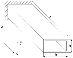
where, , and are the average displacement in , and directions. is the average displacement in twisting direction. The composite stiffness is as follow:
The inertial parameters of the composite thin-walled beam are defined in Eq. (6):
The coefficients of Eq. (5) are defined as follows:
In Eq. (8), and are the upper and lower surface coordinates respectively in the th lamina. is the number of layers. [ is the erosive eccentric plane stress stiffness matrix. (, 1, 2, 6) is the erosive orthoaxis plane stress stiffness matrix. The elements in matrices are as follows:
The transformation matrix can be defined in Eq. (10):
2.2. Solution of natural frequencies
The boundary conditions on the cantilever beam are as follows:
It is defined as following:
The general solution of the torsional vibration in Eq. (2) are as follows:
The Eq. (14) can be gained from the boundary conditions in Eq. (11):
The equation of solving the natural frequency can be gained from the second term of the Eq. (14):
The natural frequencies of the torsional vibration can be obtained from the Eq. (16):
The Eq. (14) is substituted in the Eq. (16). Then the torsional natural frequencies are gained from the Eq. (17):
The exprestions and the boundary conditions in longitudinal vibration are the same as those in torsional vibration. Then the longitudinal natural frequencies can be calculated by the the Eq. (18):
The boundary conditions on the cantilever beam in direction are as follows:
The general solution of the Eq. (4) are as follows:
The Eq. (19) is substituted in the Eq. (20), then the Eq. (21) can be gained:
The natural frequency can be solved, after the Eq. (21) is simplified:
The first four roots of the Eq. (22) are as follows:
when , the values are as follows:
The natural frequencies in direction are obtained in Eq. (25):
The equations and the boundary conditions in direction are the same with those in direction. Then the natural frequencies in direction can be gained as followings:
2.3. Natural frequencies on composite thin-walled beams
The characteristic parameters of the composite thin-walled beams are gained from the reference [13], so the natural frequency can be compared and analyzed. The parameters are 0.34.
The Table 1 shows the natural frequencies of the composite thin-walled box beams. The width of the box beams is 0.32 m, the width-height ratio is 5, the length-width ratio is 14.37. The thickness of the composite laminate is 10.16 mm. The Table 2 shows that the width-height ratio has effect on the natural frequencies of the composite thin-walled box beams. The Table 3 shows that the natural frequencies of the composite thin-walled box beams will change with different length-width ratios. The natural frequencies of the composite thin-walled circular beams are listed in the Table 4, in which the diameter is 352 mm, the length-diameter ratio is 26, and the thickness of the composite laminate is 10.16 mm. The Table 5 shows that the natural frequencies of the composite thin-walled circular beams will vary in the length-diameter ratios. All calculation results of the natural frequencies are compared with that in reference [13]. The numerical deviations are relatively small, so the model and the equilibrium equations can be used to calculate approximately the natural frequencies on the thin-walled composite beam.
Table 1Natural frequencies of composite box beams (L/b= 14.37, b/a= 5)
Layer style | ||||||
[0]16 | 3.1 | 19.7 | 11.1 | 69.5 | 39.4 | 118.3 |
Ref.[13] | 3.1 | 19.8 | 11.0 | 65.6 | 37.7 | 113.3 |
[90]16 | 1.8 | 11.4 | 6.4 | 40.3 | 39.4 | 118.3 |
Ref. [13] | 1.8 | 11.5 | 6.5 | 39.7 | 37.7 | 113.3 |
[02/902/452/–452]s | 2.4 | 14.8 | 8.4 | 52.4 | 47.9 | 143.8 |
Ref. [13] | 2.4 | 14.8 | 8.3 | 50.9 | 46.9 | 140.9 |
[45/–45]8 | 2.1 | 12.9 | 7.3 | 45.7 | 55.2 | 165.4 |
Ref. [13] | 2.0 | 12.7 | 7.1 | 44.1 | 54.6 | 164.2 |
Table 2Natural frequencies of composite box beams in different width-height ratios (L/b= 14.37)
Layer style | Ref. [13] | Ref. [13] | Ref. [13] | |||
[0]16 10 | 1.6 | 1.6 | 10.4 | 10.4 | 23.4 | 22.5 |
7.5 | 2.1 | 2.1 | 10.7 | 10.6 | 29.5 | 28.1 |
5 | 3.1 | 3.1 | 11.1 | 11.0 | 39.4 | 37.3 |
2.5 | 6.0 | 6.0 | 12.0 | 11.9 | 57.9 | 55.7 |
1 | 13.5 | 13.4 | 13.5 | 13.4 | 71.0 | 67.8 |
[90]16 10 | 0.9 | 0.9 | 6.1 | 6.1 | 23.5 | 22.5 |
7.5 | 1.2 | 1.2 | 6.2 | 6.2 | 29.5 | 28.1 |
5 | 1.8 | 1.8 | 6.4 | 6.5 | 39.4 | 37.7 |
2.5 | 3.5 | 3.5 | 7.0 | 7.0 | 58.0 | 55.6 |
1 | 7.9 | 7.9 | 7.9 | 7.9 | 71.0 | 67.9 |
[02/902/452/–452]s 10 | 1.2 | 1.2 | 7.9 | 7.8 | 28.5 | 27.9 |
7.5 | 1.6 | 1.6 | 8.0 | 8.0 | 35.9 | 34.9 |
5 | 2.4 | 2.4 | 8.4 | 8.3 | 47.9 | 46.9 |
2.5 | 4.5 | 4.5 | 9.1 | 9.0 | 70.5 | 69.3 |
1 | 10.2 | 10.1 | 10.2 | 10.1 | 86.3 | 84.5 |
[45/–45]8 10 | 1.0 | 1.0 | 6.8 | 6.7 | 32.8 | 32.6 |
7.5 | 1.4 | 1.3 | 7.0 | 6.9 | 41.2 | 40.7 |
5 | 2.1 | 2.0 | 7.3 | 7.1 | 55.2 | 54.6 |
2.5 | 3.9 | 3.8 | 7.9 | 7.7 | 81.0 | 80.6 |
1 | 8.8 | 8.7 | 8.8 | 8.7 | 99.3 | 98.3 |
Table 3Natural frequencies of composite box beams in different length-width ratios (b/a= 5)
Layer style | Ref. [13] | Ref. [13] | Ref. [13] | |||
[0]16 7.187 | 12.5 | 12.5 | 44.3 | 42.8 | 78.8 | 75.3 |
14.37 | 3.1 | 3.1 | 11.1 | 11.1 | 39.4 | 37.7 |
28.75 | 0.78 | 0.8 | 2.8 | 2.8 | 19.7 | 18.8 |
115 | 0.05 | 0.05 | 0.17 | 0.18 | 4.9 | 4.7 |
[90]16 7.187 | 7.3 | 7.3 | 25.7 | 25.5 | 78.8 | 75.3 |
14.37 | 1.8 | 1.8 | 6.4 | 6.5 | 39.4 | 37.7 |
28.75 | 0.4 | 0.4 | 1.6 | 1.6 | 19.7 | 18.8 |
115 | 0.03 | 0.03 | 0.1 | 0.1 | 4.9 | 4.7 |
[02/902/452/–452]s 7.187 | 9.4 | 9.4 | 33.4 | 32.7 | 95.9 | 93.7 |
14.37 | 2.4 | 2.4 | 8.4 | 8.3 | 47.9 | 46.9 |
28.75 | 0.6 | 0.6 | 2.1 | 2.0 | 23.7 | 23.4 |
115 | 0.04 | 0.04 | 0.13 | 0.13 | 6.0 | 5.8 |
[45/–45]8 7.187 | 8.2 | 8.0 | 29.2 | 28.2 | 110.2 | 109.2 |
14.37 | 2.1 | 2.0 | 7.3 | 7.1 | 55.2 | 54.6 |
28.75 | 0.5 | 0.5 | 1.8 | 1.8 | 27.6 | 27.3 |
115 | 0.03 | 0.03 | 0.1 | 0.1 | 6.9 | 6.8 |
115 | 0.03 | 0.03 | 0.1 | 0.1 | 6.9 | 6.8 |
Table 4Natural frequencies of composite circular beams (L/d= 26)
Layer style | ||||||
[0]16 | 3.3 | 20.4 | 3.3 | 20.4 | 41.2 | 123.4 |
Ref. [13] | 3.2 | 19.9 | 3.2 | 19.9 | 39.5 | 118.7 |
[90]16 | 1.9 | 11.9 | 1.9 | 11.9 | 41.2 | 123.4 |
Ref. [13] | 1.9 | 11.7 | 1.9 | 11.7 | 39.5 | 118.7 |
[02/902/452/–452]s | 2.5 | 15.3 | 2.5 | 15.3 | 50.1 | 150.2 |
Ref. [13] | 2.4 | 15.0 | 2.4 | 15.0 | 49.2 | 148.0 |
[45/–45]8 | 2.1 | 13.4 | 2.1 | 13.4 | 57.6 | 172.8 |
Ref. [13] | 2.0 | 13.0 | 2.0 | 13.0 | 57.0 | 172.0 |
3. Effective moduli on composite thin-walled beams
3.1. Establishment and solution of the equivalent beam
The equivalent beam is the same with the composite thin-walled beam in the length, the cross section shape and the linear density. It has the independent shear modulus and the orthotropic elastic moduli in , and directions. The expressions of the equivalent beam are as follows:
where, , and are the orthotropic elastic moduli in , and directions. is the shear modulus of the equivalent beam. is the cross-sectional area of the equivalent beam. The density of the equivalent box beam is as follows:
Table 5Natural frequencies of composite circular beams in different length-diameter ratios
Layer style | Ref. [13] | Ref. [13] | Ref. [13] | |||
[0]16 6.5 | 52.3 | 49.0 | 52.3 | 49.0 | 164.7 | 158.0 |
13 | 13.1 | 12.8 | 13.1 | 12.8 | 82.4 | 79.0 |
26 | 3.3 | 3.2 | 3.3 | 3.2 | 41.2 | 39.5 |
104 | 0.2 | 0.2 | 0.2 | 0.2 | 10.2 | 9.9 |
[90]16 6.5 | 30.3 | 29.4 | 30.3 | 29.4 | 164.7 | 158.0 |
13 | 7.6 | 7.5 | 7.6 | 7.5 | 82.4 | 79.0 |
26 | 1.9 | 1.7 | 1.9 | 1.7 | 41.2 | 39.5 |
104 | 0.12 | 0.12 | 0.12 | 0.12 | 10.2 | 9.9 |
[02/902/452/–452]s 6.5 | 39.3 | 37.7 | 39.3 | 37.7 | 200.2 | 196.8 |
13 | 9.8 | 9.6 | 9.8 | 9.6 | 100.1 | 98.4 |
26 | 2.5 | 2.4 | 2.5 | 2.4 | 50.1 | 49.2 |
104 | 0.15 | 0.15 | 0.15 | 0.15 | 12.5 | 12.3 |
[45/–45]8 6.5 | 34.3 | 32.6 | 34.3 | 32.6 | 230.4 | 228.9 |
13 | 8.5 | 8.3 | 8.5 | 8.3 | 115.2 | 114.5 |
26 | 2.1 | 2.0 | 2.1 | 2.0 | 57.6 | 57.0 |
104 | 0.13 | 0.13 | 0.13 | 0.13 | 14.4 | 14.3 |
The density of the equivalent circular beam is caculated in Eq. (29):
The principle moments of inertia on the equivalent box beam in and directions are as follows:
The principle moments of inertia on the equivalent circular beam in and directions are as follows:
By using the classical beam theory, the torsional natural frequencies of the cantilever beam are obtained in Eq. (32):
The longitudinal natural frequencies of the equivalent beam are obtained as followings:
The natural frequencies of the equivalent beam in direction are as follows:
Natural frequencies on the equivalent beam in direction are obtained as followings:
The paremeters in Eqs. (34) and (35) are calculated:
The effective moduli can be gained by the contrastive analysis of the composite thin-walled beam and the equivalent solid beam. They are only applied to an approximate dynamic analysis on the thin-walled composite beams. The approximate calculation equations are as follows:
3.2. Numerical analysis on the effective moduli
The parameters of the composite thin-walled box beam in Table 6 are chosen as follows. The width is 0.32 m. The length-width ratio is 14.37. The thickness of the composite laminate is 10.16 mm. The effective moduli on the composite thin-walled box beams are presented in Table 6. When the width-height ratios decrease, the elastic moduli in , and directions become small under the layer styles of [0]16 and [90]16, but the shear modulus increases. With the decreasing width-height ratio ratios, the elastic moduli in , directions and the shear modulus become small under the layer style of [02/902/452/–452]s, but the elastic modulus in direction increases. When the width-height ratios become small, the elastic modulus in direction and the shear modulus decrease under the layer style of [45/–45]8, the elastic modulus in direction increases, and the elastic moduli in direction decreases at first, then increases.
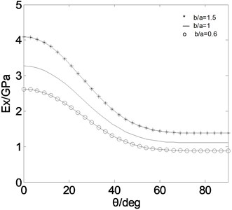
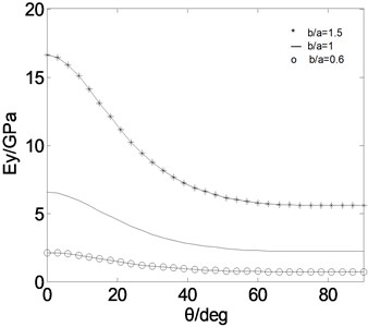
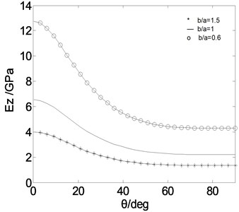
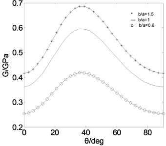
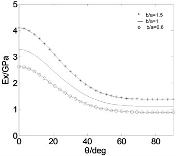
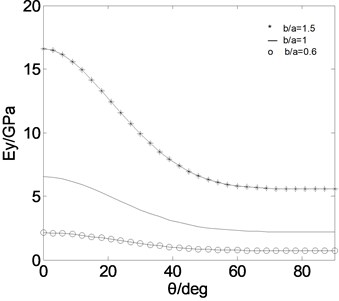
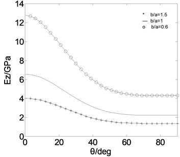
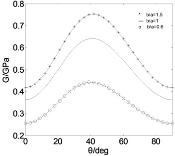
For a CUS configuration, the layer style of skin laminations at the left, right, top and bottom side are all []16, For a CAS configuration, the layer styles of skin laminations are as follows. []16 at top flange, [–]16 at bottom flange, and [/–]8 at left and right web. Fig. 2 and Fig. 3 show the effective moduli on the composite thin-walled box beams under the CUS and CAS configuration.
The elastic moduli on the composite thin-walled box beams decreases with increasing ply angels in Fig. 2. When the width-height ratios become small, the elastic moduli in and directions decrease, but the elastic modulus in direction increases. Table 6 also shows, when the ply angle comes to zero, the elastic modulus is maximal. In order to improve the elastic moduli of the composite thin-walled beams, adding the ply thickness, adopting small ply angle and large width-height ratio are all good choices.
Fig. 2(d) shows, when 38° the shear modulus on composite thin-walled box beams is maximal, and becomes small with increasing width-height ratios. Table 6 also shows, when the layer style of skin laminations is [45/–45]8, the shear moduli is maximal, and is higher than that under CUS configuration. For improving the shearing modulus on the composite thin-walled beams, we can add the ply thickness and the width-height ratio, or adopt the layer style [45/–45]8. Fig. 3 shows, the effective elastic moduli on the composite thin-walled beams under the CAS and CUS configuration are in substantial agreement. The difference of the shear modulus is obvious.
Table 6The effective moduli of composite box beams (L/b= 14.37)
Layer style | (GPa) | (GPa) | (GPa) | (GPa) |
[0]16 1.5 | 4.10 | 16.59 | 4.00 | 0.42 |
1 | 3.28 | 6.55 | 6.55 | 0.37 |
0.6 | 2.62 | 2.12 | 12.74 | 0.25 |
[90]16 1.5 | 1.38 | 5.60 | 1.35 | 0.42 |
1 | 1.10 | 2.21 | 2.21 | 0.36 |
0.6 | 0.88 | 0.72 | 4.30 | 0.25 |
[02/902/452/–452]s 1.5 | 2.33 | 9.42 | 2.27 | 0.62 |
1 | 1.86 | 3.72 | 3.72 | 0.54 |
0.6 | 1.49 | 1.21 | 7.23 | 0.38 |
[45/–45]8 1.5 | 1.77 | 7.18 | 1.73 | 0.82 |
1 | 1.42 | 2.84 | 2.84 | 0.71 |
0.6 | 1.13 | 9.19 | 5.51 | 0.50 |
Fig. 2Effective moduli on composite thin-walled box beams (CUS)
a)
b)
c)
d)
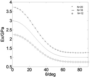
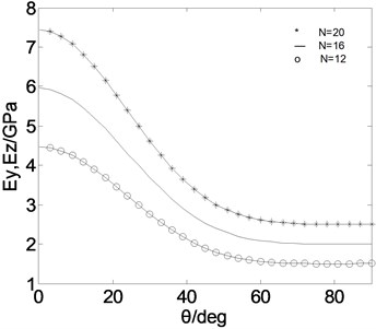
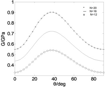
Table 7 shows the different effective moduli under different layer styles when 20, 16, 12. Fig. 4 shows the effective moduli on the composite thin-walled circular beams under the CUS configuration when 20, 16, 12. The parameters of composite thin-walled circular beams are chosen as follows: 352 mm, 26, 0.635 mm.
Table 7The effective moduli of composite circular beams (L/d= 26)
Layer style | (GPa) | (GPa) | (GPa) | (GPa) |
[0]20 | 3.72 | 7.45 | 7.45 | 0.55 |
[0]16 | 2.98 | 5.96 | 5.96 | 0.44 |
[0]12 | 2.23 | 4.47 | 4.47 | 0.33 |
[90]20 | 1.26 | 2.51 | 2.51 | 0.55 |
[90]16 | 1.00 | 2.01 | 2.01 | 0.44 |
[90]12 | 0.75 | 1.51 | 1.51 | 0.33 |
[02/902/453/–453]s | 2.02 | 4.05 | 4.05 | 0.86 |
[02/902/452/–452]s | 1.70 | 3.38 | 3.38 | 0.65 |
[02/902/45/–45]s | 1.35 | 2.71 | 2.71 | 0.43 |
[45/–45]10 | 1.61 | 3.2 | 3.2 | 1.07 |
[45/–45]8 | 1.29 | 2.58 | 2.58 | 0.86 |
[45/–45]6 | 0.97 | 1.93 | 1.93 | 0.64 |
Fig. 3Effective moduli on composite thin-walled box beams (CAS)
a)
b)
c)
d)
4. The calculating examples
4.1. The example I
There are some expressions of wind turbine blades in reference [14]. Retention of the first and second order Taylor quantity, neglecting higher-order quantity and gravity, ignoring the aerodynamic parameters and the nonlinear terms, the motion equations in , and directions can be gained in Eqs. (38), (39) and (40). The typical blade parameters are chosen for carrying out the calculation and analysis of the wind turbine blades. As the cross section of blades is universal, the rectangular blade is selected for numerical simulation. The variable parameters are as follows.
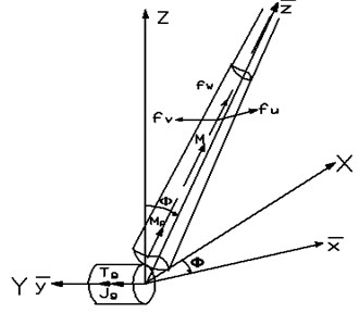
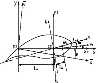
The pre-twist angle the chord length thickness of the blade . is the distance from the center of rotation. And the pitch angle length of the blade rotating speed The composite parameters are , . The composite wind blade is calculated under a CUS configuration. The layer style of skin laminations at the left, right, top and bottom side are all []96. The model of a composite turbine blade is in Fig. 5.
Fig. 4Effective moduli on composite thin-walled circular beams (CUS)
a)
b)
c)
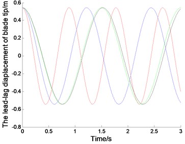
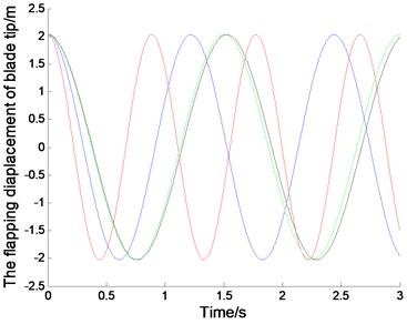
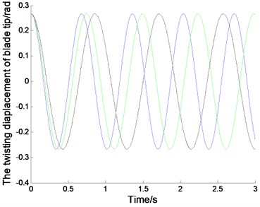
Fig. 6 represents the displacements of the composite blade in the directions of lead-lag, flapping and twisting. The initial displacements of blade tip are 0.5432, 2.0272, 0.2673. The initial displacements of other node must be selected by the linear vibration mode for the displacement continuity of continuous bar. The simulation of linear system can be achieved by Matlab/Simulink presented in [16-18]. The natural frequencies in Fig. 6 accord with those in Fig. 2. Much dynamic analysis on the composie blade can be made by the classic beam theory according to the approximate solution of the effective moduli:
Fig. 5The model of a composite turbine blade
a)
b)
Fig. 6The displacements of a composite thin-walled box blade (CUS) (the red represents θ= 0°, the blue represents θ= 30°, the green represents θ= 60°, the black represents θ= 90°)
a)
b)
c)
4.2. The example II
The model [15] of a composite thin-walled spinning beam was established in Fig. 7. Neglecting the torsional terms, the two-dimensional motion equations can be gained in Eq. (41). The chosen parameters are: the diameter 352 mm, the length-diameter ratio 26. The composite parameters of the circular beam are 0.635 mm, 1672 kg/m3, 25.8 Gpa, 8.7 Gpa, 3.5 Gpa, 0.34. The composite thin-walled circular beam is calculated under a CUS configuration. The layer style of skin laminations at the left, right, top and bottom side are all []6:
Fig. 7The model of a composite thin-walled spinning beam
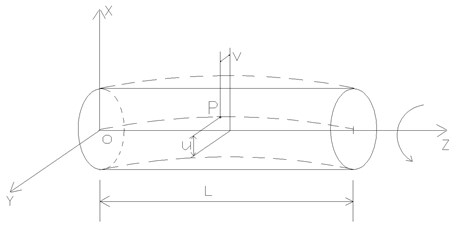
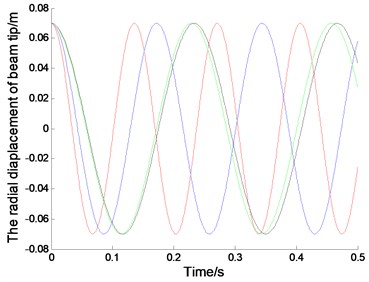
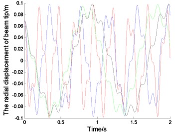
Fig. 8 represents the radial displacements of a composite spinning thin-walled circular beam, when the spinning speed 0,200 rpm. The initial displacements of blade tip are 0.0727. The initial displacements of other node must be selected by the linear vibration mode for the displacement continuity of continuous bar. The simulation of linear system can be achieved by using a finite difference method [19-20].The natural frequencies in Fig. 8 are agree with those in Fig. 4. More dynamic analysis on the composie beam can be made by the classic beam theory.
Fig. 8The displacement of a composite spinning thin-walled circular beam (CUS) (the red represents θ= 0°, the blue represents θ= 30°, the green represents θ= 60°, the black represents θ= 90°)
a) 0 rpm
b) 200 rpm
5. Conclusions
An approximate solution of the effective moduli was derived by an equivalent beam method. It can apply all the classic beam theories to the composite thin-walled beams, and made the study of the composite beams more easily. Many factors such as the layer style, the number of layer, ply angle and cross section which had effect on the effective moduli were discussed, which was useful to theoretical analysis and design optimization on the composite thin-walled beams. The algorithm is simple and clear, and can provide a new way to solve the macro moduli of the composite thin-walled beams. However, it is inaccurate, and can only be used to an approximate calculation and analysis. The variable complicated cross section is the main emphasis of future research. And improving accuracy of the algorithm is a problem that calls for immediate solution.
References
-
Eshelby J. D. The determination of the elastic field of an ellipsoidal inclusion and relateid problems. Proc. Roy. Soc., Vol. A241, 1957, p. 376-396.
-
Hashin Z. The elastic moduli of heterogeneous materials. J. Appl. Mech., Vol. 29, 1962, p. 143-150.
-
Hill R. Continuum micromechanics of elastoplastic polycrystals. J. Mech. Solids, Vol. 13, 1965, p. 89-101.
-
Christensen R. M., Lo K. H. Solution for the effective shear properties in three phase sphere and cylinder models. J. Mech. Solids, Vol. 27, 1979, p. 315-330.
-
Torquato S. Effective stiffness tensor of composite media I: Exact series expansions. J. Mech. Solids, Vol. 45, Issue 9, 1997, p. 1421-1448.
-
Bhattacharyya A., Edmonton A. Effective elastic moduli of two-phase transversely isotropic composites with aligned clustered fibers. Acta. Mechanica, Vol. 145, 2000, p. 65-93.
-
Tsai S. W., Hahn T. H. Introduction to composites design. Technomic Publish Company, Lancaster PA, 1980.
-
Wild P. M., Vickers G. W. Analysis of filament-wound cylindrical shells under combined centrifugal pressure and axial loading. J. of Comp. Mater., Vol. 10, 1996, p. 253-259.
-
Vinson J. R., Sierakowski R. L. The behavior of structure composite of composite materials. Dordrecht, Martinus Niuhoff Publishers, 1987.
-
Barbero E. J. On the mechanics of thin-walled laminated composite beams. J. Comp. Mater., Vol. 27, Issue 8, 1993, p. 806-829.
-
Whitney J. M., Browning C. E., Mair A. Analysis of the flexure test for laminated conposite material. Composite Materials: Testing and Design ASTM STP 546, American Society for Testing and Materials, 1975, p. 30-45.
-
Erian A., Ashraf M. Free vibtation analysis of anisotropic thin-walled closed-section beams. AIAA Journal, Vol. 33, 1995, p. 1905-1911.
-
Saravanos D. A. A shear beam finite element for the damping analysis of tubular laminated compsoite beams. Journal of Sound and Vibration, 2006, p. 802-823.
-
Hodges D. H., Robert A. Stability of elastic bending and torsion of uniform cantilever rotor blades in hover with variable structural couping. NASA Technical Note, 1976, p. 15-21.
-
Banerjee J. R., Su H. Dynamic stiffness formulation and free vibration analysis of a spinning composite beam. Computers and Structures, Vol. 84, 2006, p. 1208-1214.
-
Kim T. Y. Nonlinear large amplitude structural and aeroelastic behhavior of cmposite totor blades at large static defection. Thin-Walled Structures, Vol. 46, 2008, p. 1192-1203.
-
Willam H. P., Saul A. T. Numerial recipes. 3rd ed., Cambridge Press, 2007, p. 192-203.
-
Hansen M. H. Aeroelastic stability analysis of wind turbines using an eigenvalue approach. Wind Energy, Vol. 7, 2004, p. 133-143.
-
Zhu Y. F. A study of stability of large wind turbine blades. WNWEC, Vol. 9, 2010, p. 173-179.
-
Zhu Y. F. Numerical analysis of twist for a horizontal axis turbine blade. CESM, Vol. 3, 2011, p. 43-48.
About this article
This work was financially supported by the National Science Foundation (10972124) and science and technology project of department of education of Shandong Province (J08LB04).
