Abstract
The modal analysis of the automobile transmission housing assembly is formulated using 3D graphics software Pro/E together with Finite Element Method in order to reduce the noise and vibration by accurately identifying the noise source of the transmission in the neutral idle condition. Besides, the calculation of meshing frequency of gear pair is conducted. After comparing model analysis results with the calculation results, we can intuitively analysis the dynamic characteristics of the transmission housing assembly and find out sensitive parts of the housing vibration. In order to enhance the structural stiffness of the transmission housing assembly and allow intentionally the natural frequency of the transmission to avoid the gear meshing frequency, we increase the thickness of thin plate or add the strengthening rib on the weak parts of the transmission housing assembly. The results of the above modified modal reanalysis show that low mode frequencies of the transmission housing assembly are greatly improved after optimization, and avoid the gear meshing excitation frequency effectively. The probability of resonance for the transmission housing assembly in use will be greatly reduced, which can well achieve the purpose of enhancing the dynamic characteristics of the transmission housing assembly.
1. Introduction
The automobile transmission housing, a complex thin-walled spatial structural part, is adopted to support and position the components in the automobile transmission, bearing various dynamic loads in the whole travel process of the automobile, and it also plays a key role in maintaining stable and efficient work of the whole transmission system. Along with the rapid development of science technology and automobile industry, the increasingly stringent control requirements on vehicle noise were put forward by the national regulations. At the same time, car buyers have higher and higher demand for riding comfortability, the vibration and noise has become one of the key indices of vehicle performance. The noise of automotive power transmission system has a very large proportion in the whole automobile noise, furthermore automotive transmission is the key parts of automobile power transmission system, thereby reducing the noise of automobile transmission is significant for reducing the noise of the whole vehicle [1, 2]. The so-called neutral idle abnormal noise phenomenon, refer to a significant noise arising from the transmission housing as long as the transmission coupled to the clutch, when the vehicle is in a suspended state, the transmission hanging in the neutral position, the engine running at idle speed (about 700-800 rpm), which can be obviously distinguished from the sound with the clutch disengaged from the transmission [3]. A domestically-made automobile, with three shafts and five speed transmission, owns obvious noise in neutral idle condition, which can be clearly heard by car drivers, and seriously affects the ride comfort. The abnormal noise greatly reduces the vehicle sound quality, makes it easy for customers to produce the illusion that the vehicle has a design and manufacturing quality problems, moreover has seriously affected the vehicle market competitiveness [4].
A large number of studies report that the main source of the high noise of transmission in the idle condition mainly includes two aspects: one is the gear meshing noise generated by mutually alternating meshing of each gear pair when the transmission was at work; the other is the fluctuation of the engine output torque and rotational speed, causing the normal gear meshing relationship destroyed, thus excited vibration and then emitted the impact noise [5].
Based on the comprehensive analysis of the noise radiation mechanism of the transmission housing, the paper introducers a finite element modal analysis to the whole transmission, and studies the inherent frequency and vibration condition of the transmission housing assembly, as well as meshing frequency of every gear pair of the transmission in the neutral idle condition. Through comparative analysis between the inherent frequency of the transmission housing assembly and meshing frequency of every gear pair, as well as the vibration diagram of the transmission housing assembly and its dynamic display, the noise resource in the neutral idle condition was quickly and accurately identified and the weak spots of transmission is intuitively analyzed. In order to ensure that certain inherent frequency of the transmission housing assembly should avoid the meshing frequency of every gear pair of the transmission in the neutral idle condition, some measures are taken to establish the dynamics optimization design of the transmission. The paper firstly adopts the conventional solution to increase the wall thickness or to add the strengthening rib on the outlet end of the transmission housing, to strengthen the structural stiffness of the transmission housing assembly. However, analysis results are not very satisfactory. Based on the above analysis, further measures are then adopted on the suspension bracket of the transmission housing, the results of the above modal reanalysis show that low mode frequencies of the transmission housing assembly are greatly improved after optimization, and avoid the gear meshing excitation frequency effectively, which can well achieve the purpose of improving or optimizing the dynamic characteristics of the transmission housing assembly. Meanwhile, it also provides an effective way for optimal design of dynamic performance of the transmission housing assembly.
2. Noise source identification
The radiation noise of the transmission housing accounts for more than 90 percent of the whole transmission system noise, therefore, through simulating the real motivation acting on the transmission, the study on the noise radiation of the transmission housing under the action of the motivation is very meaningful.
There are two general ways in which the transmission usually spreads the noise outward: one is the direct formation of the noise radiation due to the metal bump, which will produce reverberation in the transmission housing, whereinto, only a small portion of noise radiates out through the transmission housing wall, most of the remaining acoustic energy was dissipated by structural damping and other damping element; the other is the structure vibration due to gear bump, which will be transferred through the gear, gear shaft, the bearing to the transmission housing, and then produce the large vibration in the sensitive parts of the transmission housing to radiate the noise. The latter is a more effective spreading route, and playa a leading role on noise radiation of the transmission [6].
Considering that the above transmission radiation noise comes mainly from the vibration excitation of the transmission housing due to the gear meshing impact, this article will use the modal analysis of the transmission housing to determine which gear pair has significant contribution to the abnormal noise of the transmission in neutral idle condition, and also analyze the weak spots of transmission to lay a solid foundation on the dynamics optimization design of the transmission. This will help us make the certain inherent frequency of transmission avoid the meshing frequency of every gear pair of the transmission in the neutral idle condition. Only in this way can we guarantee the dynamic characteristics of the gearbox assembly.
3. Modal analysis of the transmission housing
Automobile transmission is a multiple degree of freedom vibration system. A variety of exciting force acting on this system is the power and source to make the transmission produce complex vibration [7]. Modal analysis is the base for vibration and noise analysis. Through the implementation of modal analysis on the transmission housing, the resonance phenomenon could be avoided in the structural design of the transmission housing as far as possible [8]. In this paper, we will take a certain type of transmission for example, firstly establish the three-dimensional solid model of the transmission, and then establish the finite element model of the transmission to perform modal analysis.
3.1. Establishment of 3D model of transmission housing
The practical model of automobile transmission is quite complex, distributed with various reinforcing ribs, bosses, oil drain hole, corners and fillets, and all kinds of bolt connection holes and so on. The gear box comprises five forward gears and one reverse gear. The gear box adopts a constant mesh gear transmission. The synchronizer, as gear shift mechanism, can make the input power be transmitted through different gear pairs, while the realization of the different transmission ratio.
In order to exert the result of modal analysis to be close to the actual situation to the fullest extent, simplification of transmission structure should be reduced to as little as possible, to ensure that the calculation results have high precision, can more truly reflect the vibration characteristics of transmission structure. However, too small feature structure in the transmission housing has almost no effect on modal analysis, further, these small structures, such as small screw thread hole or sharp fillet, can generate thousands of nodes and elements when establishing the finite element model. Too small feature structure needs to divide into very small cell, thereby increasing the amount of data processing, can result from the inability of analysis. Therefore, simplification of transmission structure is necessary.
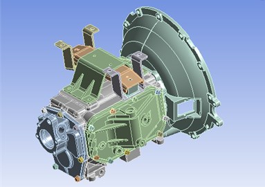
Considering that the mass matrix and stiffness matrix of 3D solid model of transmission housing could not completely accord with the actual situation, we will establish a simplified model of transmission housing based on the equivalence principle. Meanwhile, full consideration should be given to the factors that play a dominant role in the modal analysis of transmission housing, especially the suspension bracket of the transmission housing, which plays an important supporting role on the transmission housing assembly, and will influence the modal analysis results of the transmission housing assembly in some extent. Therefore, the suspension bracket should be included in the transmission housing assembly as a whole to carry out the comprehensive analysis, in order to obtain the whole structure's mode. The powerful wildfire 4.0 Pro/E software is adopted to establish the three-dimensional entity assembly model of the transmission housing assembly as shown in Fig. 1.
Fig. 13D assembly model of the transmission housing assembly
3.2. Establishment of FEA model of transmission housing
The finite element mesh generation is the key technique of the computer assistance engineering analysis (CAE). A large number results of test research indicates that the meshing density is a key step in Finite Element analysis, which has great influence on computing time and accuracy of Finite Element analysis, so both aspects must be weighed correctly while determining the meshing density. Generally speaking, the smaller the meshing density is, the higher the calculation accuracy is, but the longer the computing time is proportionately, and otherwise, it will make a big difference. Under ideal operation condition, the needed meshing density may occur when the following conditions occur: the results of finite element analysis don’t vary with the increase of the numbers of the mesh [9]. Based on such consideration above, the author gives a pathbreaking study of the model analysis of transmission housing in different meshing densities, which focuses on comparing all analysis results with different meshing densities.
In this study, the material parameters used in calculation are as follows: the material is grey cast iron HT200, material density is kg/m3, elasticity module 110 GPa, Poisson’s ratio . Three-dimensional entity model from Pro/E software can be imported directly into FEA software, all kinds of property from entity model in the Pro/E can be inherited entirely, which includes initial position parameter and mass property of all components of the transmission housing assembly. The mesh generation of finite element model of the transmission housing assembly has a total of node 194917, element 366191, as shown in Fig. 2.
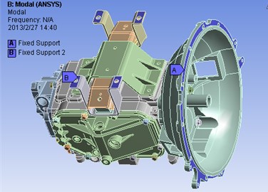
In general, the modal analysis contains free modal and constrained modal, considering that the constraint mode is closer to the actual working mode, this paper will apply the constrained mode to study the finite element modal analysis of the transmission housing assembly based on the actual use of the transmission. Because the mode is determined by the inherent characteristics of the system, and has nothing to do with the external load, it is not necessary to set the external load and boundary condition other than zero displacement constraint conditions. Because the transmission housing is connected to the vehicle body through the suspension bracket in the actual installation, in order to accurately reflect the actual state of the transmission housing, the fixed constraints will be applied on the mounting frame, as shown in Fig. 3.
Fig. 2Meshing the finite element model of the transmission housing assembly
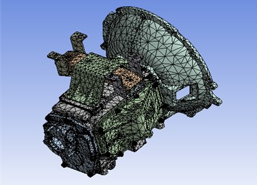
Fig. 3The constrained model of the transmission housing assembly
3.3. Modal analysis results of transmission housing
Based on the modal analysis of transmission, the natural frequencies and mode shapes of the transmission housing are studied, and transmission vibration sensitive parts are also theoretically analyzed and calculated. In finite element analysis, in order to simulate test conditions of transmission, zero displacement constraints are attached in the input shaft cover connecting section to go in for calculation of the transmission housing constrained mode. In general, the main reason of causing engine resonance is the lower order frequency of transmission housing. Therefore, in the use of ANSYS solution and extension mode, it is enough to expand and extract the former 14 order frequencies of transmission. When conducting modal analysis of the transmission housing in the boundary condition, the first 6 order modes are close to zero, this is so-called rigid body mode. Therefore, the truly meaningful mode should be started from seventh order mode. In this paper, ANSYS workbench is used to calculate the first 14 order modes, remove the first 6 order rigid body mode and extract the first 8 order non-zero modes as shown in Table 1. The above results from Table 1 show that the frequency distribution of gearbox is close, which is perfectly consistent with the complex appearance and structure of the transmission.
Table 1Previous 8 orders modal frequencies of the transmission housing and the clutch
Modal order | 1 | 2 | 3 | 4 | 5 | 6 | 7 | 8 |
Frequency (Hz) | 214.51 | 245.73 | 492.79 | 513.2 | 662.93 | 681.13 | 826.76 | 894.5 |
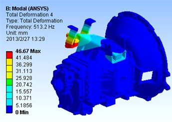
The first 4 order modal shapes of the gearbox housing assembly are shown in Fig. 4 to Fig. 7. Through the animation demonstration of above 4 mode maps, we can find that the first-order modal shape can be seen as the overall vibration, mainly for the horizontal hunting around axis (vertical direction) near the outlet end of the transmission housing, and the maximum amplitude appears in the shifting shaft cover; the second-order modal shape can be also seen as the overall vibration, mainly for the vertical hunting around axis (horizontal direction) near the outlet end of the transmission housing, and the maximum amplitude also appears in the shifting shaft cover; the third-order modal shape can be seen as the partial vibration, mainly for the torsion vibration near the right end of suspension bracket of the transmission housing, the most intense vibration appears in the right fixing plate of the mounting plate; the fourth-order modal shape can be also seen as the partial vibration, mainly for the torsion vibration near the left end of suspension bracket of the transmission housing, the most intense vibration appears in the left fixing plate of the mounting plate.
Fig. 4The first-order modal shapes of the gearbox housing assembly
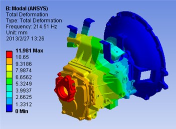
Fig. 5The second-order modal shapes of the gearbox housing assembly
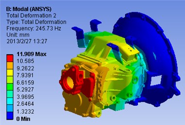
Fig. 6The third-order modal shapes of the gearbox housing assembly
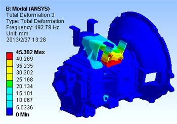
Fig. 7The fourth-order modal shapes of the gearbox housing assembly
4. Meshing frequency of gear pair
4.1. Excitation of gear meshing to produce noise
In automobile transmission system, the transmission is the second most important component part only to the engine, directly relates to the automobile manipulation of fun and ride comfort. The transmission is mounted between the clutch and the transmission shaft, adjusts the power and speed of the engine, then transfers to a drive shaft, plays an important role in the allocation function.
The transmission is a kind of multi gear pair transmission machinery. It is inevitable to produce different degrees of running noise in any mechanical drive. The transmission noise is much more complex than the single gear transmission mechanism, which is the irregular random combination of many sound waves with different frequencies and intensity. The signal of sound waves will be distributed over the entire frequency range. Hence, as far as the automobile is concerned, the transmission is also a passive vibration noise source and excitation source.
4.2. Calculation of meshing frequency of gear pair
Generally, 5 gear and constant mesh gear pair of the transmission are in motion in neutral idle condition. Some studies show that the abnormal noise source of the transmission in neutral idle condition are mainly for meshing gear pairs when the processing and assembly precisions meet the requirement, so it is necessary to calculate the meshing frequency of every gear pairs [10].
The gear pair meshing frequency calculation formula can be expressed as:
Axial rotation frequency formula can be expressed as:
where is the speed of axis (r/min), and stands for the number of teeth on a gear.
The so-called neutral idle abnormal noise phenomenon, refer to a significant noise arising from the transmission housing as long as the transmission coupled to the clutch, when the vehicle is in a suspended state, the transmission hanging in the neutral position, the engine running at idle speed (about 700-800 rpm), which can be obviously distinguished from the sound with the clutch disengaged from the transmission.
The speed range of the transmission input shaft in the neutral idle condition is about 700-800 rpm, this paper respectively calculates meshing frequency of the transmission gear pair in three speed point, that is 700 rpm, 750 rpm and 800 rpm. When the transmission input shaft speed in the neutral idle condition is 700 rpm, the input shaft rotation frequency can be calculated as 11.667 Hz, considering that the fourth gear is directly installed on the input shaft, the meshing transmission of the fourth gear pair will drive the middle shaft, so the middle shaft rotation frequency can be calculated as 7.9545 Hz. Hence, the corresponding meshing frequency of each gear pair is as shown in Table 2.
Table 2Meshing frequency of each gear pair with the input shaft speed 700 rpm
Gears | First | Twice | Third | Fourth | Fifth |
Number of teeth of input shaft | – | – | – | 30 | – |
Number of teeth of middle shaft | 14 | 22 | 35 | 44 | 54 |
Number of teeth of output shaft | 45 | 37 | 34 | – | 29 |
Mesh frequency / Hz | 111.3636 | 175 | 278.409 | 350 | 429.5454 |
When the transmission input shaft speed in the neutral idle condition is 750 rpm, the input shaft rotation frequency is 12.5 Hz and the middle shaft rotation frequency can be calculated as 8.52727 Hz. So the corresponding meshing frequency of each gear pair as shown in Table 3.
Table 3Meshing frequency of each gear pair with the input shaft speed 750 rpm
Gears | First | Twice | Third | Fourth | Fifth |
Number of teeth of input shaft | – | – | – | 30 | – |
Number of teeth of middle shaft | 14 | 22 | 35 | 44 | 54 |
Number of teeth of output shaft | 45 | 37 | 34 | – | 29 |
Mesh frequency / Hz | 119.318 | 187 | 298.295 | 375 | 460.2273 |
When the transmission input shaft speed in the neutral idle condition is 800 rpm, input shaft rotation frequency is 13.33 Hz and the middle shaft rotation frequency can be calculated as 9.0909 Hz. So the corresponding meshing frequency of each gear pair as shown in Table 4.
Table 4Meshing frequency of each gear pair with the input shaft speed 800 rpm
Gears | First | Twice | Third | Fourth | Fifth |
Number of teeth of input shaft | – | – | – | 30 | – |
Number of teeth of middle shaft | 14 | 22 | 35 | 44 | 54 |
Number of teeth of output shaft | 45 | 37 | 34 | – | 29 |
Mesh frequency / Hz | 127.2727 | 200 | 318.1818 | 400 | 490.9091 |
By solving the finite element model of the transmission housing assemble, the first, third and fourth order modal frequencies of the transmission housing assemble are 214.51 Hz, 492.79 Hz and 513.2 Hz respectively, at the same time, through the calculation of the gear pair meshing frequency of the automobile transmission in neutral idle condition. The research results offer foundation neutral idle condition, the meshing frequencies of the twice and fifth gear pairs are 200 Hz and 490.9091 Hz, close to the first, third and fourth order modal frequencies of the transmission housing assemble, which will cause the resonance phenomenon, and then generate the abnormal noise.
After comprehensive evaluating the transmission mode analysis results, combined with the operation principle of transmission, the gear meshing impact noise of the twice and fifth gear pairs was identified as the noise resource for further establishing the noise control measure, give some rational improvement proposals for local structure of the transmission with severe vibration, which aims at reducing vibration and noise.
5. Optimization modal analysis of transmission housing
Based on the modal analysis results of the transmission housing assembly, relative to other parts of the transmission housing assembly, both of the outlet end of the transmission housing and the suspension bracket of the transmission housing have low modal frequencies, prone to resonance with the excitation frequency. Through observation of the first 4 order vibration modes, sensitive parts of the transmission housing assembly with larger amplitude vibration focus on the left fixing plate of the mounting plate and shifting shaft cover, which might be called the areas of weakness under low order mode of the transmission housing assembly as shown in Fig. 4 to Fig. 7. Therefore, in order to allow the natural frequency of the transmission to avoid the gear meshing frequency, the key to improve the whole mode frequency of the transmission housing assembly is to improve the design of the weak parts of the transmission housing assembly, so as to reduce the structural deformation and improve the overall structural performance.
It is advisable to increase the thickness of thin plate or add the strengthening rib to enhance the structural stiffness of the transmission housing assembly, in order to improve the low order modal frequency and reduce the vibration amplitude of the transmission housing assembly. Considering that the main load acts on the transmission housing, not on the mounting frame of the transmission housing, so the paper adopts the conventional solutions, that is, on the premise that there is no interference in the transmission housing assembly, the wall thickness and strengthening rib should be applied in the outlet end of the transmission housing with large amplitude, especially the rectangle reinforcement plate frame with good torsional stiffness and bending stiffness, to strengthen the structural stiffness of the transmission housing assembly as shown in Fig. 8. The modified transmission housing assembly is carried on the modal reanalysis, and the first 8 order modal frequencies are shown in Table 5. However, the results of the above modal reanalysis show that the structural optimization of the transmission housing assembly according to the above conventional ideas and routes couldn’t achieve the desired results, go further and say, the natural frequency of the transmission in the modified transmission housing assembly couldn’t avoid the gear meshing frequency effectively.
Table 5Previous 8 order modal frequencies of the modified transmission housing assembly
Modal order | 1 | 2 | 3 | 4 | 5 | 6 | 7 | 8 |
Frequency (Hz) | 211.25 | 243.31 | 501.56 | 517.13 | 664.94 | 703.4 | 858.91 | 920.84 |
Therefore, based on the above analysis, we implement the second project, that is, the thickness of the suspension bracket of the transmission housing is increased from 5 mm to 8 mm, as shown in Fig. 9. The further modified transmission housing assembly is also carried on the modal reanalysis, and the first 8 order modal frequencies are shown in Table 6.
The results of the above modal reanalysis show that low mode frequencies of the transmission housing assembly are greatly improved after optimization, especially the third order frequency is increased from 492.79 Hz to 573.01 Hz, so as to avoid the gear meshing excitation frequency effectively. So it can be expected that the probability of resonance for the transmission housing assembly in use will be greatly reduced, which can well achieve the purpose of improving or optimizing the dynamic characteristics of the transmission housing assembly. Meanwhile, it also provides an effective way for optimal design of dynamic performance of the transmission housing assembly.
Fig. 83D assembly model of the modified transmission housing assembly
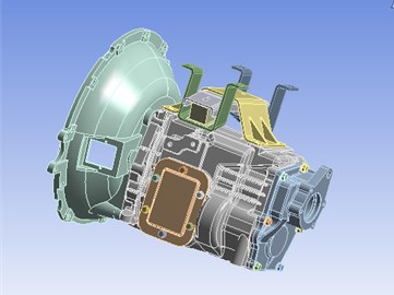
Fig. 93D assembly model of the further modified transmission housing assembly
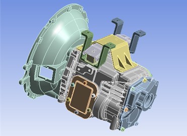
Table 6Previous 8 order modal frequencies of the further modified transmission housing assembly
Modal order | 1 | 2 | 3 | 4 | 5 | 6 | 7 | 8 |
Frequency (Hz) | 217.5 | 248.94 | 573.01 | 622.13 | 700.48 | 704.6 | 840.32 | 896.45 |
6. Conclusions
In this paper, in response to the neutral idle abnormal noise phenomenon arising from a domestically-made automobile, based on the establishment of the finite element model of the transmission housing assembly and its modal analysis, the natural frequency of the transmission housing assembly was estimated, and analysis results can be generated to find transmission vibration sensitive parts. In addition, the calculation of meshing frequency of gear pair is conducted also. Through comparing model analysis results to the calculation results, both of the outlet end of the transmission housing and the suspension bracket of the transmission housing have low modal frequencies, prone to resonance with the excitation frequency. Therefore, some methods have been taken to increase the thickness of thin plate or add the strengthening rib on the weak parts of the transmission housing assembly to enhance the structural stiffness of the transmission housing assembly. The modal reanalysis results after optimization show that the integral stiffness of the transmission housing assembly is enhanced, and mode frequencies of the transmission housing assembly are greatly improved, so as to avoid the gear meshing excitation frequency effectively and then obviously increase the vibration resistance of the transmission housing assembly, which will ensure the comprehensive quality and working stability of the transmission housing. This paper will provide an effective way to some extent for the dynamics optimization design of the transmission structure and has theoretical significance value to analyze its dynamic characteristics of the transmission as well as its improvement to reduce vibration and noise.
References
-
Q. Shi, D. Guo, X. Shi Identification of the abnormal noise in the transmission of a domestic car and its redesign. Journal of Southwest University, Vol. 5, 2010, p. 158-161.
-
Q. Shi, Y. Long, X. Shi Parameter optimization of transmission gear clusters and squeak noise control. Noise and Vibration control, Vol. 3, 2011, p. 46-49.
-
G. Feng Effectively reduce abnormal noise of automobile in the neutral position. Modern Components, Vol. 7, 2010, p. 79-83.
-
Z. Chu, Z. Deng, L. Wang Idle abnormal noise source identification for a midder-duty truck. Journal of Vibration and Shock, Vol. 28, 2009, p. 179-181.
-
Z. Chu, Z. Deng, Y. Hu Noise control for SC6350C vehicle transmission. China Mechanical engineering, Vol. 16, 2005, p. 1481-1485, (in Chinese).
-
H. Okamura Study of low noise structures about transmission and clutch components on the dive line of commercial vehicle. JSAE review, Vol. 4, 19963, p. 5-38.
-
W. Wang, C. Xiang, H. Liu Study on the radiation noise of gearbox housing based on FEM/BEM. Noise and Vibration control, Vol. 27, 2007, p. 107-111.
-
B. Li, Z. He, X. Chen Design, simulation and optimization of ANSYS Workbench. Tinghua University Press, Beijing. 2008, in Chinese.
-
Y. Li, W. Xia, W. Shen Structural optimum design and analysis of the mast of rotary drilling rig based on finite element method. Research Journal of Applied Science, Engineering and Technology, Vol. 4, Issue 18, 2012, p. 3222-3230.
-
J. Liang, D. Wang, Y. Jiang The noise source identification and noise control of automobile transmission. Noise and Vibration Control, Vol. 3, 2006, p. 67-70.
About this article
This work was financially supported by the Opening Project of Key Laboratory of Testing Technology for Manufacturing Process, (Southwest University of Science and Technology), Ministry of Education (11ZXZK06) and Zhejiang Postdoctoral Science Foundation (BSH1302020).
