Abstract
Nowadays one of the major topics in the brake development community is the NVH (noise, vibration and harshness) problem. Although reasonably well researched in the disc brake systems, the squeal prediction in the drum brakes is often neglected, manly due to its complexity. The newly developed methodology presented in this work gives the directions on how to develop a squeal free drum brake design using some novel approaches to closely correlate the numerical results with the experimental brake tests. The goal is to make a robust drum brake design that is stable under the different noise factors and under broad operational conditions. In order to predict if a brake system will generate the squeal noise during the operation, the finite element method was used to simulate the system. By solving the complex eigenvalues of the FEM (finite element method) matrices, the presence of unstable modes was predicted. A good correlation with the SAE J2521 noise matrix dynamometer test procedure was established.
1. Introduction
The braking process in an automobile involves a contact of metallic solids sliding against each other, which sometimes generates undesirable noise, vibration, and harshness (NVH). Brake squeal is known as an annoying high-pitched single-tone noise [1].
Brake squeal is becoming an increasing concern to the automotive industry because of the warranty costs and the requirement for the reduction of the interior vehicle noise. The majority of the research has been directed to either analytical and experimental studies of the brake squeal mechanisms or the prediction of the brake squeal propensity using finite the element methods. By comparison, there is a lack of systematic analysis of brake squeal data obtained from a noise dynamometer [2].
As Oberst and Lai [2] have pointed out, the majority of the research undertaken over the last two decades has focused primarily on exploring the mechanism of brake squeal using simplified analytical models or applying the finite element method (FEM) complemented by experiments to determine unstable vibration modes in a brake system. The general conclusion was that in the foreseeable future no complete and practical solution is most likely in sight.
More specifically, the finite element (FE) method is the preferred method in studying brake squeal. Finite element analysis (FEA) is popular due to the inadequacy of experimental methods in predicting squeal at the early stage in the design process. Moreover, FEA can potentially simulate any changes made on the drum brake components much faster and easier than experimental methods [3].
Drum brakes operate by pressing a set of brake linings against a rotating drum. The friction between the linings and the drum causes deceleration, but it may also induce a dynamic instability of the system, known as brake squeal. One possible explanation for the brake squeal phenomenon is the coupling of the two neighbouring modes. Two modes, which are close to each other in the frequency range and have similar characteristics, may merge as the friction contribution increases. When these modes merge at the same frequency (become coupled), one of them becomes unstable. The unstable mode can be identified during the complex eigenvalue extraction because the real part of the eigenvalue, which corresponds to the unstable mode, is positive. The brake system design can be stabilized by changing the geometry or material properties of the brake components to decouple the modes.
In this study, the 8 inch rear drum brake assembly from a mid-sized passenger automobile was analysed. The goal of the study is to develop a stable complex eigenvalue modal analysis methodology that has a strong correlation to the dynamometer squeal test results. To the authors’ knowledge, this is the first published research where the detailed analysis of the NVH problem using newest findings in the squeal prevention such as the complete drum brake assembly complex eigenvalue analysis are combined and closely related with experimental results on the brake dynamometer using the SAE J2521 procedure.
2. Background
The goal of a robust design is to make a brake system stable under the noise factors (variations) and broad operational and environmental conditions with the optimized trade-off of function, weight, and cost at an early design stage. In other words, the goal is to obtain a broadly stable brake system – a system that is stable under various component/assembly variations and usage conditions [4].
Fig. 1Design tools and methods for achieving a NVH robust design used in automotive industry
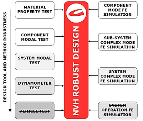
Figure 1 shows summary of currently available design tools and methods. Some tools such as the vehicle test and system operation FE simulation are not yet being used by the brake development engineers because of the high complexity and costs. Neither numerical simulation methods nor even road tests alone are sufficient to completely evaluate the brake system squeal probability. The efficient way to optimize and verify the results is to integrate all CAE methods and test techniques in the development process.
Component-level numerical analysis on modal characteristics using the finite-element method is mature and straightforward. It can provide mode shape and frequencies of the brake components [1], but it does not take the system interactions into account and thus the results are not always close to reality. Therefore, the system complex mode FE simulation is preferred in the brake research community, as it allows all unstable frequencies of the system to be found in one run for one set of the operating conditions and hence it is very efficient. Complex eigenvalue analysis provides a conservative approach, as it predicts all unstable modes that may grow into a limit-cycle vibration. Which modes indeed grow into the limit-cycle vibration and the amplitudes of the resultant limit-cycles, found from a transient analysis, depends on triggering mechanisms [5].
In other words, if the complex mode FE simulation and optimization is used in the stable brake system development, the system is always on the safe side and is not likely to produce any squeal.
3. Complex eigenvalue analysis of a brake system
3.1. Complex eigenvalue modal analysis theory
Brake squeal can be defined as a self-excited vibration caused by fluctuations in the friction forces at the lining-drum interfaces. Fluctuations caused by friction coefficient-velocity characteristics and fluctuations due to normal forces between the lining and the drum (even if the friction coefficient is constant) are the two theories to explain the cause of the friction force fluctuation. The FEM has already been used to predict the eigenvalues of the simplified drum brake systems. For a 3-D FEM model, each node has three DOFs (degrees of freedom). For any node at the lining – drum interfaces, Coulomb’s friction law is used to relate the DOFs in the normal direction to the DOFs in the two tangential directions, causing the resulting FEM matrices to become unsymmetrical. By solving the complex eigenvalues of the newly formed matrices, one can predict if any unstable mode will be present. Any complex eigenvalues with a positive real part may indicate an unstable mode, which may result in a squeal. The real part of a complex eigenvalue is called “propensity”; the larger is its magnitude, more likely the mode is unstable [6].
The governing equation of the system is:
where , and are respectively the mass, damping and stiffness matrices, and is the displacement vector. Because of friction, the stiffness matrix has specific properties:
where is the structural stiffness matrix, the asymmetrical friction induced stiffness matrix and the friction coefficient. The governing equation can be rewritten as:
where is the eigenvalue and is the corresponding eigenvector. Both eigenvalue and eigenvector may be complex. In order to solve the complex eigen problem, this system is symmetrized by ignoring the damping matrix and the asymmetric contributions to the stiffness matrix . Then this symmetric eigenvalue problem is solved in order to find the projection subspace. The eigenvectors obtained from the symmetric eigenvalue problem are expressed in a matrix as . Next, the original matrices are projected onto the subspace of eigenvectors:
then the projected complex eigenproblem becomes:
finally, the complex eigenvectors of the original system can be obtained by:
Detailed description of the formulation and the algorithm are presented by Sinou et al. [7]. The eigenvalues and the eigenvectors of Eq. (3) may be complex, consisting of both a real and imaginary part. For under damped systems the eigenvalues always occur in the complex conjugate pairs. For a particular mode, the eigenvalue pair is:
where and are the damping coefficient (the real part) and damped natural frequency (the imaginary part) describing damped sinusoidal motion.
In order to predict if a disk brake system will generate squeal, the finite element method (FEM) is used to simulate the system. At the contact interfaces between the linings and the drum, the normal displacement is continuous and Coulomb’s friction law is applied. Thus, the resulting FEM matrices of the dynamic system become unsymmetrical, which will yield complex eigenvalues [6]. The complex eigenvalue analysis (CEA) has been widely used by researchers. In order to perform the complex eigenvalue analysis using Abaqus [9], four main steps are required as follows:
• nonlinear static analysis for the application of brake pressure ,
• nonlinear static analysis to impose a rotational velocity on the drum ,
• normal mode analysis to extract the natural frequency to find the projection subspace, and
• complex eigenvalue analysis to incorporate the effect of friction coupling.
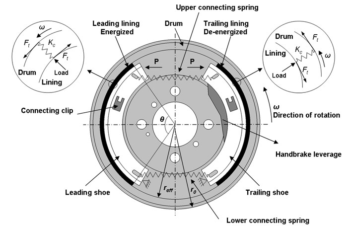
Figure 2 shows the schematic diagram of the drum brake assembly showing piston pressure , direction of rotation and contact stiffness representation.
There is no need to introduce contact springs at the interface as Abaqus uses direct contact coupling as proposed by Yuan [10] and Blaschke et al [11]. Abaqus/Standard automatically detects the contact nodes that are slipping due to velocity differences imposed by the motion of the reference frame or the transport velocity in prior steps. At those nodes, the tangential degrees of freedom will not be constrained and the effect of friction will result in an unsymmetric contribution to the stiffness matrix. At other nodes in contact, the tangential degrees of freedom will be constrained.
Friction at contact nodes at which a velocity differential is imposed can give rise to damping terms.
Fig. 2Schematic diagram of the brake drum assembly
3.2. Spring coefficient measurement
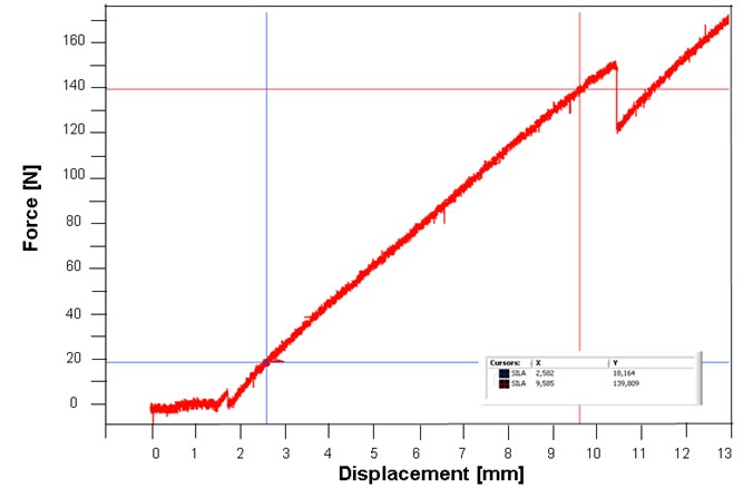
In order to simplify the numerical model generation, the lower and the upper connecting springs shown in Figure 2 were replaced with the numerical spring elements. The spring coefficient was measured in the CIMOS brake producer company material laboratory on a universal Wolpert TZZ 100 kN tensile testing equipment. Test range of the connecting springs was 5 kN. Figure 3 and 4 shows the upper and the lower connecting spring coefficients. It can be seen that the response in the measuring range is linear, so the springs were replaced with the preloaded linear wedge type C3D6 elements. There is some non-linearity in the force-displacement graphs, which can be attributed to the slip of the spring in the clamping device. Using the two points in the linear part of the diagrams, the spring coefficient can easily be calculated.
Fig. 3Force displacement diagram of the upper connecting spring
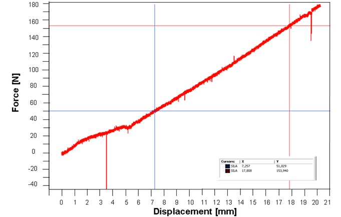
Fig. 4Force displacement diagram of the lower connecting spring
3.3. Complex eigenvalue modal analysis results
The brake system was modelled using Catia V5R19 modelling software. The developed model was then imported into Abaqus 6.11, where the FE analysis was made.
Some of the material properties used in the analysis were tested in the CIMOS laboratory on MTS 810 tensile testing equipment at room temperature and are plotted in Table 1.
Table 1Material data of brake components at room temperature
Density – [kgm-3] | Poisson number – [/] | Elastic module – [MPa] | |
Drum | 7200 | 0.24 | 100000 |
Friction material | 2540 | / | Orthotropic |
Lining body | 7850 | 0.3 | 210000 |
Wheel bolt | 7800 | 0.3 | 210000 |
Hub | 7300 | 0.3 | 170000 |
Connecting pin | 7850 | 0.3 | 210000 |
Connecting clip | 7850 | 0.3 | 210000 |
Backplate | 7850 | 0.3 | 210000 |
Handbrake leverage | 7850 | 0.3 | 210000 |
Cable holder | 7850 | 0.3 | 210000 |
Distancers | 7850 | 0.3 | 210000 |
Connecting pin | 7850 | 0.3 | 210000 |
Numerical simulation was performed using the model of a full brake assembly as seen in Figure 5 (the backplate was removed for a better visualization), which consists of a brake drum, linings, wheel bolts, hub, connecting pins, connecting clips, backplate, handbrake lever, handbrake cable holder and distancers. A finite element mesh with 141420 C3D8R elements, 79512 C3D10 elements and 26 C3D6 elements was used. Using such a large model signifies a very time-consuming computation but it is crucial for an accurate squeal prediction. The mesh was refined at the brake drum – brake lining interface as seen in Figure 5.
Fig. 5Brake assembly mesh
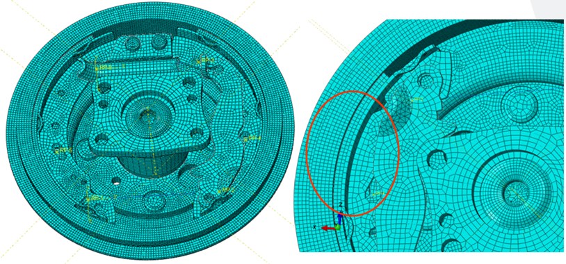
In the first step, the contact between the brake linings and the brake drum is established by applying the pressure of 20 bar. Next, the slipping condition on the brake lining-brake drum interface is defined by inducing a rotational velocity of 9.89 rad∙s-1 (corresponds to vehicle speed of 10 km∙h-1) on the brake drum. The average value of friction coefficient was set to 0.49. Those values were chosen on the basis of statistical study of experimental results shown in Figures 12, 13 and 14. The most representative or critical ones were used in order to simulate the actual squeal dynamometer test. It was discovered that large friction coefficient combined with a small lining pressure is the most likely to produce squeal.
Both, the positive and negative friction-induced damping effects are included in addition to asymmetrical contribution to the stiffness matrix. In this analysis, the effect of friction damping is considered along with a constant friction coefficient. The friction damping term in ABAQUS can be activated by specifying in the input file. This damping is caused by the friction forces that are stabilising vibration along the contact surface in direction perpendicular to the slip direction [3]. The friction damping may suppress some of unstable modes.
Fig. 6Unstable eigen frequencies of the drum brake system
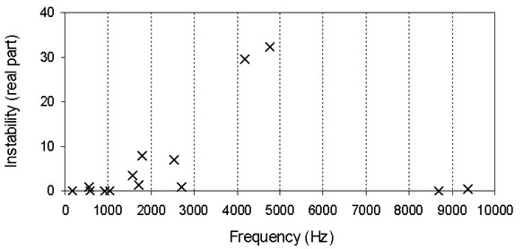
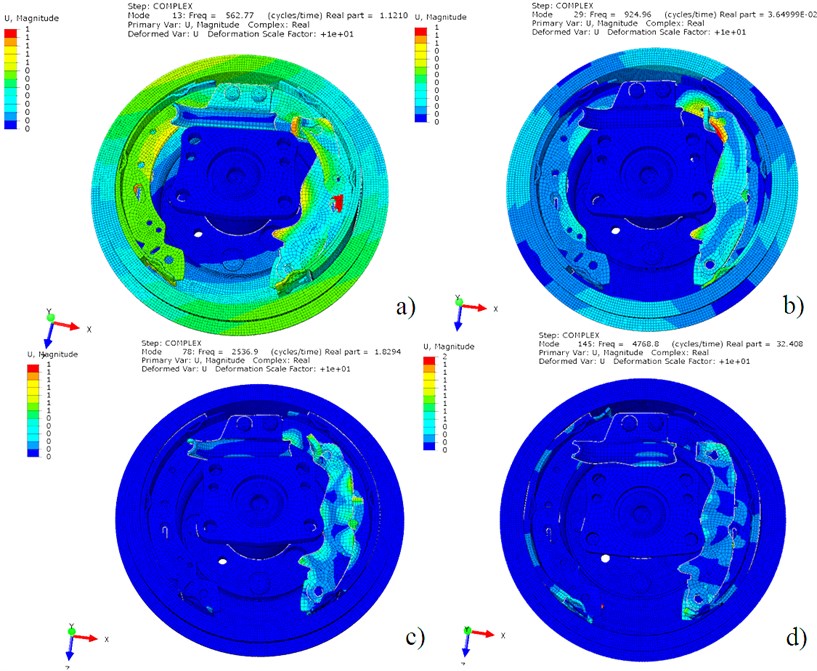
Fig. 7Unstable eigen frequencies of the drum brake system
In order to connect the brake components, surface-to-surface three-degrees of freedom contact elements were employed. It was proven that such modelling can predict unstable frequencies up to 20 kHz very well [12]. A rigid boundary condition is imposed at the boltholes of the backplate, where all six DOFs are rigidly constrained.
The results of the complex eigenvalue modal analysis are shown in Figure 6. The ones that have the real part larger than 0 are assumed to be unstable and, therefore, can cause the brake system squeal. The larger is the real part, the larger is the possibility that the brake system will squeal at that exact eigen frequency. The positive real parts of the complex eigen values indicate the degree of instability of the disc brake assembly and are thought to indicate the likelihood of squeal occurrence, and not its magnitude. The drum brake is most likely to squeal at around 4800 Hz and 4100 Hz, but is mostly unstable at 2500, 1800, 1500, 500 and 900 Hz as well.
Some of the most critical eigen modes are presented in Figure 7. Figures show that the brake component that is mostly unstable is the hand brake leverage that causes most of the high-frequency instabilities as seen in Figures 7(c) and 7(d). The reason is the loose clamping of the component onto the brake lining. The modification of the hand brake leverage is proposed in order to raise its stiffness.
The majority of the car producers believe that the most responsible component for the brake squeal is the brake drum. But as seen in the mode shapes in Figure 7, the brake drum resonates only at low frequencies (up to 2000 Hz).
Figures 7(a) and 7(b) represent the most critical brake drum mode shapes. In the Figure 7(a) the brake drum resonates in the mode shape 0/1 and in the Figure 7(b) the drum resonates in the mode shape 2/0. The proposal is to raise the stiffness of the brake drum in order to raise those critical eigen frequencies. By doing so, the brake drum mode shape will not interact with the brake lining mode shapes and the instability will be solved.
4. Contact pressure distribution
The simplex drum brake presented in this analysis has two shoes performing differently. Based on the generated energy, one is called the self amplifying shoe or leading shoe and the other is the self-debilitating shoe or trailing shoe as seen from Figure 2. As the forward or leading shoe contacts the drum, the drum attempts to rotate the shoe along with it but the shoe cannot rotate because it is fixed by an anchor or pivoted. The drum rotation, therefore, energizes the shoe by forcing it outward and wedging it tightly against the brake drum. This action produces a form of self amplification system brake. The drum also attempts to rotate the trailing shoe when it contacts the drum in the far end of the shoe which is not solidly anchored. So drum rotation will de-energize the shoe by forcing it inward away from the brake drum. A leading shoe is always energized by drum rotation meanwhile a trailing shoe is always de-energized by drum rotation [13].
Figures 8 and 9 illustrate the changes that take place in the contact patch for both leading and trailing shoes under static and pseudo-dynamic conditions.
Figures 9(a) and 9(b) show the static pressure distribution for both leading and trailing shoes. The centre of pressure is concentrated towards the “toe” area of each shoe. The magnitude of the maximum pressure is the same for both components. It is also observed that the edges of the shoes that lie towards the open end of the drum have lost contact. This is due to the deflection of the drum. Finally, the contact patches obtained from the two shoes are not located in identical positions on the lining, due to the asymmetric attachment of the linings on the platforms [14].
Figures 9(c) and 9(d) illustrate the predicted pseudo-dynamic pressure distribution. The computational results illustrate typical drum brake contact behaviour. Following the drum’s rotation, the centre of pressure for the leading shoe moves towards the abutment end. The magnitude of maximum lining pressure and the contact area has increased in relation to the static values. This is due to the introduction of friction forces, which create a moment about the leading shoe’s pivot point, causing the shoe to move further towards the drum surface and consequently increasing the maximum lining pressure.
Fig. 8Changes in displacement in trailing/leading shoe due to rotation of the brake drum: a) after pressure apply, b) after pressure and rotation apply
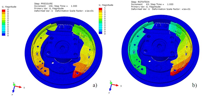
Fig. 9Changes in pressure in trailing/leading shoe due to rotation of the brake drum: a) trailing shoe before rotation, b) leading shoe before rotation, c) trailing shoe after rotation, d) leading shoe after rotation

This phenomenon is known as the positive self-servo effect. Similarly, the trailing shoe experiences the so-called negative self-servo effect [14]. In this case, the trailing shoe pulls away from the drum and as a consequence the lining’s maximum pressure and contact area are reduced compared to the static conditions.
Contact distribution plays a critical role in the complex eigenvalue analysis squeal prediction. The contact patterns shown in Figure 9 represent only the new, unworn condition. Therefore, the squeal predicted in this methodology only serves to simulate the new drum brake squeal. Nevertheless, the brake homologation tests performed by automotive industry are always done on new drum brakes, so the methodology can serve as a homologation test simulation.
5. Experimental results
SAE J2521 squeal matrix dynamometer test procedure was chosen to test the methodology. It is a laboratory evaluation test for critical conditions as it replaces the driveway, parking lot, city and highway driving. It is a global standard test used by the original equipment manufactures (OEMs), tier 1, tier 2, and aftermarket suppliers of friction and brake products. The test is considered to be non-destructive in the context that none of the conditions simulated (stops, decelerations or temperatures) are outside the conditions that may be reasonably expected from drivers.
Dynamometer testing data are generally known to have a good correlation to vehicle tests. However, some sensitive parameters must be under control, such as compressibility, FRF (frequency response function), configuration, etc. Repeated dynamometer testing can minimize the risk of wrong conclusion [15].
In order to receive the representative data, 5 brake drums were tested. The brake drums were taken from the same batch; the linings and the backplate were replaced for each new test. The brake linings were also taken from the same batch and their hardness was measured. Only the linings with comparable hardness were used in the test.
Fig. 10Brake dynamometer test setup
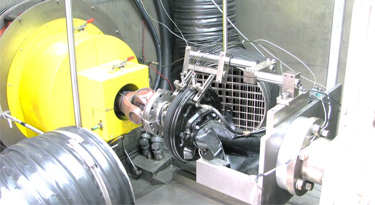
The tests were performed in CIMOS brake testing laboratory in Koper, Slovenia, on a full NVH LINK 3900 Dynamometer. The installation included the same brake components as the numerical analysis. As seen in Figure 10, the backplate was installed on the rear suspension at the dynamometer tailstock and the brake drum was driven by the flexible shaft mounted on the brake drum wheel hub. The microphone was positioned according to the SAE J2521 – 500 mm above the brake system and 100 mm axially moved away from the brake system towards the flexible shaft.
The summary of all test stops, at which the recorded noise was above 50 dB(A) is plotted in Figure 11. The boundary of squeal is set above 70 dB(A). The squeal was mainly recorded at around 2500 Hz, which is the most critical frequency, and also at 2800, 4100 and 900 Hz.
The analysis of all noisy stops (above 70 dB(A)) was made in order to produce feedback information for numerical analysis. Figures 12, 13 and 14 represent the dependency of those noisy stops on average pressure during each braking, average friction coefficient during braking and initial speed, respectively. The majority of noisiest stops occurred at average pressure of 30 bar, brake factor 2.8 and initial speed of 10 km∙h-1.
Brake effectiveness in Figure 13 is defined on the ratio between the total friction force or moment on the shoes to and the applied force or moment at the tip of the shoes. It is also called the brake shoe factor or brake factor . The brake factor is an assessment criterion for the brake performance as it indicates the ratio of braking force to actuating force. This value takes into account the influence of the internal transmission ratio of the brake as well as the friction coefficient, which in turn is mainly dependent on the parameters such as speed, brake pressure and temperature.
Fig. 11Maximal sound pressure level (SPL) recorded at all stops for all tests
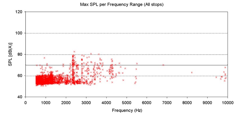
Fig. 12Noisy stops dependency of average pressure during the braking
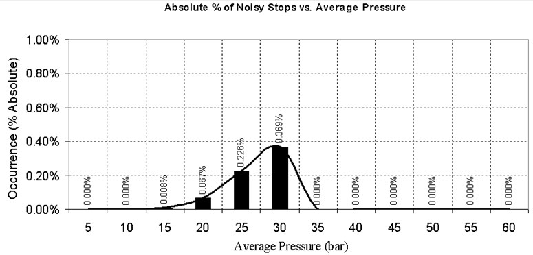
Fig. 13Noisy stops dependency of brake factor C* during the braking
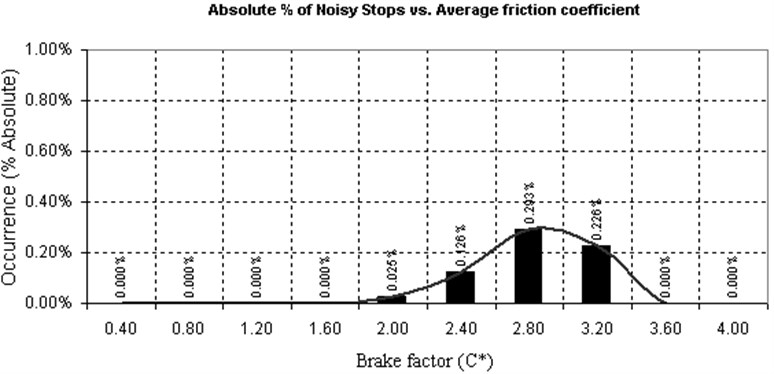
Fig. 14Noisy stops dependency of initial braking speed before the braking
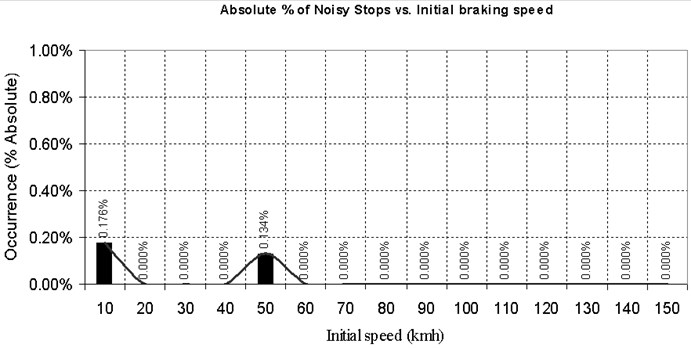
Fig. 15Schematic diagram of the brake drum assembly: 1 – duo-servo drum brake, 2 – duplex drum brake, 3 – simplex drum brake, 4 – disc brake
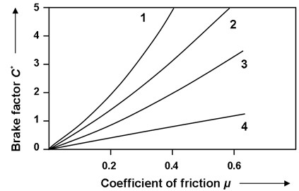
Figure 15 shows the empirical value of the brake factor for different types of brakes as function of the friction coefficient. Drum brakes have a higher brake factor than the disc brake because of the self-amplification effect described in Section 4. Drum brakes, especially the duo-servo drum brakes, have a high stopping power but they are also more sensitive to the friction coefficient. Although the disc brake produces the lowest brake factor, it has the lowest sensitivity to the friction coefficient. The drum brake shoe factor does not change linearly with the friction coefficient [13]. Based on Figure 15, the friction coefficient was determined for the simplex drum brake analyzed in this work.
6. Conclusion
In this work, a drum brake has been analyzed for the NVH properties. A procedure has been proposed in order to achieve a squeal free acceptable design. First some proposals are given on how to perform a complex eigenvalue analysis of a drum brake and how to correlate the results with the experimental brake dynamometer tests. Secondly, the analysis of the current state of a brake assembly is made, and the methodology is proposed in order to separate the critical mode shapes of the brake components and to achieve a stable design.
In order to predict if a drum brake system will generate squeal during the operation, the finite element method was used to simulate the system. By solving the complex eigenvalues of the FEM matrices, the presence of the unstable modes was predicted. The most unstable mode is calculated at around 4100 Hz, but is unstable at 4800, 2500, 1800, 1500, 500 and 900 Hz as well, as seen from Figure 6. The SAE J2521 test procedure was performed on 5 brake assemblies on the LINK brake dynamometer in the brake testing laboratory in brake producer CIMOS D. D. The summary of recorded noise of all test stops is plotted in the Figure 11. The boundary of the squeal is set above 70 dB(A). The squeal was mainly recorded at 2500 Hz, which is the most critical frequency, and at 2800 Hz, 4100 Hz and 900 Hz, which is in good correlation with the complex eigenvalue modal analysis.
If we compare the results of the CEA plotted in Figure 6 with the results of the experiment plotted in Figure 11, it is clear that all major critical modes that were recorded during the experiment were predicted by the CEA. Even more, CEA predicted some of the critical modes that were later not seen in the experiment. There is one major reason for that.
The complex eigenvalue analysis predicts all unstable modes that may grow into the limit-cycle vibration. Which modes indeed grow into the limit-cycle vibration found in the dynamometer tests, depends on triggering mechanisms. It is clear from the Figure 11 that only modes at 2500, 4100, 2800 and 900 Hz were triggered by the conditions in which the test took place.
References
-
M. Pevec, D. Vraneševič, G. Oder, I. Potrč, M. Šraml. Modifying the brake drum geometry to avoid self excited vibration and noise. Journal of Vibroengineering, Vol. 14, Issue 2, 2012.
-
S. Oberst, J. C. S. Lai. Chaos in brake squeal noise. Journal of Sound and Vibration, Vol. 330, 2011, p. 955-975.
-
A. R. Abu-Bakar, H. Ouyang. Recent studies of car disc brake squeal. New Research on Acoustics, Chapter 4, 2008, p. 159-198.
-
R. L. Quaglia, F. Chen. Squeal Reduction and Prevention. Disc Brake Squeal: Mechanism, Analysis, Evaluation and Reduction/Prevention, SAE Press, 2006.
-
H. Ouyang, W. Nack, Y. Yuan, F. Chen. Numerical analysis of automotive disc brake squeal: a review. International Journal Vehicle Noise and Vibration, Vol. 1, No. 3, 2005.
-
G. Lou, T. W. Wu, Z. Bai. Disc brake squeal prediction using the ALBE algorithm. Journal of Sound and Vibration, Vol. 272, 2004, p. 731-748.
-
J. J. Sinou, F. Thouverez, L. Je’ze’quel. Analysis of friction and instability by the center manifold theory for a non-linear sprag-slip model. Journal of Sound and Vibration, Vol. 265, No. 3, 2003, p. 527-559.
-
M. Nouby, D. Mathivanan, K. Srinivasan. A combined approach of complex eigenvalue analysis and design of experiments (DOE) to study disc brake squeal. International Journal of Engineering, Science and Technology, Vol. 1, No. 1, 2009, p. 254-271.
-
A. Bajer, V. Belsky, L. J. Zeng. Combining a nonlinear static analysis and complex eigenvalue extraction in brake squeal simulation. SAE Technical Paper 3349, 2003.
-
Y. Yuan. An eigenvalue analysis approach to brake squeal problems. Proceedings of the Dedicated Conference on Automotive Braking System, 29th ISATA, June 1996.
-
P. Blaschke, M. Tan, A. Wang. On the analysis of brake squeal propensity using finite element method. SAE Technical Paper, 2000.
-
G. Chen, P. Wu, H. Dai, U. Zhou. Comparative study on the complex eigenvalue prediction of brake squeal by two infinite element modelling approaches. Chinese Journal of Mechanical Engineering, Vol. 23, 2010.
-
M. N. B. A. Hamid. A Study on the Effect of Out of Roundness of Drum Brake Rotor on the Braking Force Using the Finite Element Method. Master of Science Thesis, 2007.
-
P. Ioannidis, P. C. Brooks, D. C. Barton. Prediction of drum brake contact pressure distribution and its effect on squeal propensity. JUMV Conference Paper, 2005.
-
J. Lou, A. Lock. Noise Dynamometer and Vehicle Test Correlation, Disc Brake Squeal: Mechanism, Analysis, Evaluation and Reduction/Prevention. SAE Press, 2006.
About this article
Operation part was financed by the European Union, European Social Fund.
Special thanks to CIMOS Automotive Industry, Slovenia for their support of the research.
