Abstract
Mitigating methane emissions into the atmosphere to reduce adverse effects on the environment and climate is a primary goal of the environmental strategies employed by PJSC Gazprom and the Russian Federation as a whole. Experts warn that the planet is confronting a critical situation due to greenhouse gas emissions. This study examines the most effective technologies currently available for recovering gas from compressor station equipment. Based on an assessment of their strengths and weaknesses, a new system known as the Mobile Ejector Unit (MEU) has been proposed. The MEU utilizes a two-stage jet ejector, with its key characteristics derived from calculations based on G.N. Abramovich's methodology. Additionally, the study presents modification schemes for the valve unit to facilitate the MEU's connection, as well as gas recovery schemes from the centrifugal booster circuit and the compressor workshop circuit. An analysis of evacuation times based on different recovery schemes was conducted, along with an economic assessment of the MEU's implementation efficiency. The findings indicate that this technology is both effective and adaptable, owing to its operational simplicity, cost efficiency, and mobility.
1. Introduction
Evaluating and mitigating methane emissions into the atmosphere to lessen environmental harm and climate effects are primary goals of the environmental policies of PJSC Gazprom and the Russian Federation overall.
Experts indicate that the planet is facing a critical crisis due to greenhouse gas emissions. At the G20 International Summit, the 16th meeting of the Group of Twenty, held on October 30-31, 2021 in Rome, Italy, it was once again concluded that it is necessary to keep the warming process at a level of 1.5°C by finding effective solutions.
PJSC Gazprom annually allocates significant financial resources towards environmental protection goals and conducts activities to reduce greenhouse gas emissions. If the share of saved natural gas during repair works in 2021 was 45 %, then for 2022, PJSC Gazprom has set this indicator at 75 % [1]. Therefore, measures for further reducing emissions are highly profitable.
Rational use of lost gas provides an opportunity to benefit from raw material savings and reduce environmental payments.
In the technological process of natural gas trunk transportation, there are inevitable losses associated with the need for equipment repairs and operational features. Among such losses is the venting of gas from repaired sections of gas pipelines, compressor station (CS) equipment, and gas pumping units (GPUs) during shutdowns. Modern developments are aimed at reducing these losses and implementing gas conservation technologies, such as:
1) Utilization of gas from the compressor shop circuit (CSC) for internal needs of the CSC.
2) Diversion of gas from a disconnected section of the gas pipeline or CSC circuit to the inlet of CS or to an adjacent section of the pipeline coming out of repair.
3) Utilization of gas from a disconnected section of the gas pipeline using GPUs to feed units of the next CS or multi-stage utilization of GPUs on one CS.
4) Use of mobile compressor stations (MCS).
5) Application of ejectors [2].
Let’s consider the most effective methods.
A mobile compressor station is a complicated assembly of primary and supporting equipment intended to preserve gas while operating on main gas pipelines. The main equipment consists of a mobile compressor unit, high-pressure compressor, gas piston engine, and air cooling apparatus [3].
The main drawback of MCS is the high cost of this system, which leads to unprofitability when extracting small volumes of natural gas.
A simpler complex for gas extraction is represented by a gas ejector. This device operates by increasing the total pressure of one (ejected) flow by mixing it with another (ejecting) flow with higher total pressure. It works based on accelerating gas flow through channel constriction and expansion.
The principle of operation of an ejector (Fig. 1) is as follows. The active (ejecting) gas is supplied to the inlet chamber through a nozzle in the ejector. Passing through the nozzle, the gas expands to a pressure close to atmospheric. Due to the pressure difference in the evacuated chamber and the receiving chamber of the ejector, the gas enters the mixing chamber and mixes with the stream of active gas. At the outlet of the device, the mixed flow has a higher pressure than the pressure of the ejecting gas.
Fig. 1Ejector circuit diagram: 1 – ejection gas nozzle; 2 – ejection gas nozzle; 3 – mixing chamber; 4 – diffuser

The technology of gas extraction using an ejector is characterized by low manufacturing cost, high productivity, simple design, operational reliability, and other advantages compared to analog equipment. A notable example of applying this technical solution is the “Arskaya” compressor station, where a method for extracting gas from a stopped gas pumping unit is implemented [4, 5]. As a result, three-quarters of the gas previously vented into the atmosphere can be saved.
A significant drawback of this method is its stationary implementation, which requires installing and setting up an ejector at each compressor station node. This led to the proposal of a new, more versatile technology for extracting natural gas from compressor station equipment.
2. Result of investigation
Based on the analysis of existing gas extraction systems, it can be concluded that there is no universal technology that allows gas extraction during repair works on compressor station equipment without using complex technological connections.
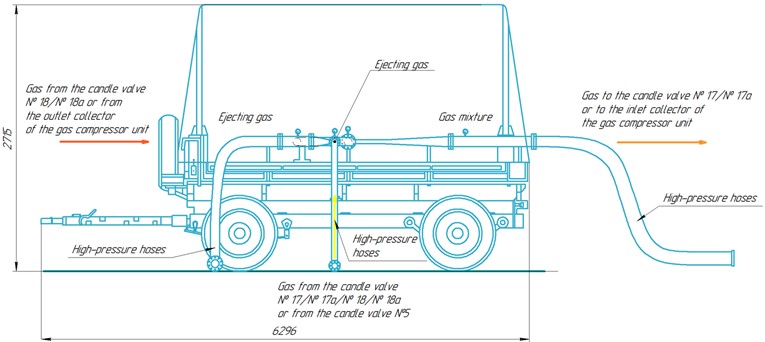
To enhance efficiency and reduce costs in gas extraction from compressor station equipment, a mobile ejector unit (MEU) is proposed. It can be designed as a mobile platform (Fig. 2) that moves to the necessary locations in the compressor shop where gas extraction is required.
The main equipment includes a jet two-stage ejector and a technological setup with quick-connect fittings, high-pressure hoses, steel pipelines, shut-off valves, check valves, and pressure gauges. The compactness and cost-effectiveness of the mobile ejector are undeniable advantages compared to a mobile compressor station.
For the operation of the ejector unit, a pressure differential equal to the pressure increase in the compressor shop is required. The main task in calculating the ejector using G.N. Abramovich’s methodology [6] is determining the gas mixture parameters at the outlet of the mixing chamber based on the parameters of gases before mixing. The calculation is based on three conservation equations: energy, mass, and momentum.
Fig. 2Mobile ejection unit

The temperature, pressure, and mass flow rate of the ejecting gas of the first stage are assumed constant and equal to T1= 293,15 K, p*1=7,451 MPa, G1= 8,330 kg/s respectively.
The temperature, pressure, and mass flow rate of the ejected gas of the first stage are assumed constant and equal to T2= 293,15 K, p*2= 0,6 MPa, G2= 0,833 kg/s respectively.
The ratio of the total pressures of gases is calculated using the formula:
Π0=7,451⋅1060,6⋅106=12,419.
Ejection coefficient or relative gas flow rate:
n=0,8338,330=0,1.
The ejector is designed to operate at the most advantageous critical mode. Due to the relatively high ratio of total pressures of gases Π0= 12,419 and the small ejection coefficient, it is advisable to select an optimal supersonic nozzle for the ejecting gas. For complete expansion of the ejecting gas, the nozzle should be designed for pressure ratios (k= 1, 4):
p*1p2=12,4190,5283=23,507.
The exit section of the nozzle coincides with the throttling section, where the ejected gas moves at critical velocity. The reduced velocity the exit section of the nozzle coincides with the throttling section, where the ejected gas moves at critical velocity. The reduced velocity λ1 at the exit of such a nozzle is determined:
π(λ1)=123,507=0,043.
Then, the λ1p, q(λ1)p values are found from the table of gasdynamic functions and will be respectively λ1p= 1,88, q(λ1)p= 0,3211.
The area of the exit section of the nozzle will be equal to (neglecting total pressure losses in the nozzle):
Fp=Fkr0,3211=3,114⋅Fkr.
To achieve the highest total pressure of the mixture, the nozzle should be designed with incomplete gas expansion, so that the area of the exit section is smaller than the calculated nozzle area. In this case, according to the formula:
valid for Π0= 5–300 by n⋅√θ= 0-0,6. Here, √θ – the ratio of critical velocities (the square root of the ratio of stagnation temperatures).
It is assumed that the ratio of stagnation temperatures is equal to 1, then √θ=1:
Therefore, the optimal area of the exit section of the nozzle:
The reduced velocity of the ejecting gas at the exit of the optimal supersonic nozzle is determined from the continuity equation:
q(λ1)0=12,273=0,441.
From the gasdynamic functions table, λ1= 1,77 is found.
The gasdynamic function z(λ1) is determined as:
Next, the value of the reduced velocity λ2 at the critical mode (λ'2= 1) is determined using the following equations:
The simultaneous solution of these equations is found by trial and error. A series of values for λ'1, is set, with the initial approximation compared to the calculated value of λ1p= 1,88, taking into account that for the optimal nozzle λ'1<λ1p.
Since the gas parameters at the exit of the optimal nozzle are slightly different from the parameters at the critical section, small differences are formed in the right-hand sides of the equations. Therefore, calculations based on these formulas need to be carried out with a high degree of precision.
By setting the value as described above, λ'1= 1,85, λ2= 0,48, q(λ2)= 0,685 are determined:
The required geometric parameter α of the ejector is found from the formula:
Then:
α=112,419⋅0,1⋅1⋅0,6850,441=1,257.
Resulting in the ratio of the chamber cross-sectional area to the nozzle exit area:
F3F1=1,257+11,257=1,796,
And to the critical nozzle area:
F3Fkr1=1,7960,441=4,075.
The main ejection equation or momentum equation is then determined:
By substituting λ1, λ2 and n and n into the equation:
z(λ3)=2,335+0,1⋅2,5560,1+1=2,355.
Despite the flow in the mixing chamber being supersonic in this case (λ'2= 1), it is necessary to find a subsonic solution to the equation as well. This solution corresponds to the most advantageous flow deceleration mode in the shock located directly at the outlet section of the chamber:
λ3=22,355+√2,3552-4=0,556.
Then, q(λ3)= 0,772 is determined.
The total pressure of the mixed flow at the exit of the mixing chamber is found:
p*3=7,451⋅106⋅0,1+11+11,257⋅0,4410,772=2575853Pa=2,576MPa.
The temperature, pressure, and mass flow rate of the ejecting gas in the second stage are assumed constant and equal to T1= 293,15 K, p*1=7,451 MPa, G1= 91,630 kg/s respectively.
The temperature, pressure, and mass flow rate of the ejected gas in the second stage are assumed constant and equal to T2= 293,15 K, p*2=2,576 MPa, G2= 9,163 kg/s respectively.
The values for the second stage of the gas ejector were calculated (Table 1).
Table 1Results of calculation of the second stage of the gas ejector
Indicator | Meaning | Indicator | Meaning | Indicator | Meaning |
Π0 | 2,855 | F0 | 1,013 | α | 1,821 |
n | 0,1 | q(λ1)0 | 0,988 | F3/F1 | 1,549 |
p*1/p2 | 5,405 | λ1 | 1,10 | F3/Fkr1 | 1,569 |
π(λ1) | 0,185 | z(λ1) | 2,009 | z(λ3) | 2,127 |
λ1p | 1,510 | λ'1 | 1,45 | λ3 | 0,702 |
q(λ1)p | 0,721 | λ2 | 0,34 | q(λ3) | 0,892 |
Fp | 1,387 | q(λ2) | 0,509 | p*3 | 5779539 |
F0/Fp | 0,730 | z(λ2) | 3,306 |
Based on the calculation results, it is sufficient to use two stages of gas flow mixing to achieve the required parameters (Fig. 3). Different connection options are used to form these stages.
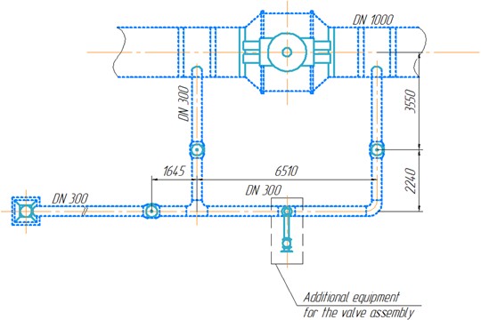
To enable the connection of the mobile ejector unit, valve assemblies need to be retrofitted (Fig. 4). For different gas extraction schemes, retrofitting is done on the bypass pipeline of the valve assembly by installing a line with a quick-release flange connection. Various connection methods can be used for extracting the ejecting and ejected gas flows.
Fig. 3Schematic diagram of the calculated two-stage gas ejector

Fig. 4Diagram of additional equipment of the crane assembly for MOU connection

Gas extraction from the casing of the centrifugal compressors is carried out through pre-equipped candle valves No. 5, with the active flow formed by diverting gas from the output collector of the gas compressor unit to the input (Fig. 5).
Fig. 5Gas generation diagram from GPU piping

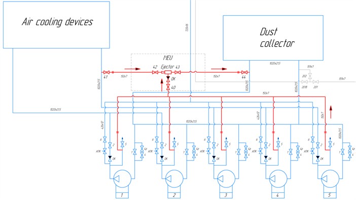
Gas extraction from the compressor shop circuit involves at least two compressor units. The connection is made through pre-equipped candle valves No. 17, 17a, 18, 18a (Fig. 6).
To increase pumping efficiency, multiple ejectors can be installed (Fig. 7).
Fig. 6Diagram of gas generation from CC circuit by one ejector

Fig. 7Diagram of gas generation from CC circuit by two ejectors

As noted earlier, pumping performance may vary depending on the number of ejectors used. The pumping speed and pumping time were calculated depending on the circuit used (Table 2).
Table 2Performance of mobile ejection unit
Parameter | Value |
Pumping speed, st.m3/min | 85,135 |
Pumping speed, st.m3/h | 5108, 095 |
Evacuation time from the centrifugal compressor unit (1540 st.m3), min | 18 |
Evacuation time from the CCU container (104720 st.m3) using one ejector, h | 20 |
Evacuation time from the CCU container (104720 st.m3) using two ejectors, h | 10 |
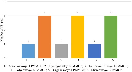
Fig. 8Distribution of the number of compressor stations by branches of Gazprom Transgaz Ufa LLC

The values of gas losses and financial savings that can be achieved by using a mobile ejector unit for ventilation of compressor circuits (Table 3), including at various gas pumping stations, were calculated (Fig. 8).
The main economic efficiency indicators of the mobile ejector unit are met (Table 4) and are calculated for extraction from nine compressor stations of various gas compressor stations.
Table 3Economic impact of reducing natural gas emissions
Name | 1 CC | 5 CC | 1 CS | 3 CS | 9 CS |
Gas losses, thousand m3 | 18,474 | 92,370 | 104,720 | 314,160 | 942,480 |
Fee for greenhouse gas emissions, million rub./year | 0,015 | 0,075 | 0,086 | 0,258 | 0,774 |
Cost of lost gas, million rub./year | 0,111 | 0,555 | 0,629 | 1,887 | 5,661 |
Fee for permissible emissions of pollutants, million rub./year | 0,004 | 0,020 | 0,020 | 0,060 | 0,180 |
Total financial losses, million rub./year | 0,130 | 0,650 | 0,735 | 2,205 | 6,615 |
Table 4Performance indicators of mobile ejection unit
Efficiency indicators | Value | Efficiency criterion | Compliance with efficiency criterion |
Net profit, thousand rubles | 8574 | > 0 | Criterion is met |
Profitability index | 2 | > 1 | Criterion is met |
Criterion is metInternal rate of return, % | 68 | > 13,8 (discount rate) | Criterion is met |
Payback period, years | 1,5 | < 10 | Criterion is met |
3. Conclusions
According to the conducted study, the mobile ejector unit proves to be a cost-effective solution for reducing greenhouse gas emissions into the atmosphere. Its key advantage lies in its mobility and relative affordability. The payback period significantly exceeds that of current analogs, and the simplicity of the design allows for reduced maintenance and operating costs of this equipment.
References
-
“Environmental Report of PJSC Gazprom for 2021,” PJSC Gazprom, PJSC Gazprom, 2022.
-
G. N. Ruban et al., “Gazovyj Ezhektor,” (in Russian), RU Patent Utility Model 2559115, 2014.
-
“Mobile Compressor Stations.” Gazprom ISS LLC, 2024, https://mks.gazprom.ru/about/working/
-
R. R. Kantyukov et al., “The system and method of pumping gas from the compressor of the gas pumping unit,” (in Russian), RU Patent Utility Model 2652473, 2018.
-
M. V. Chuchkalov and A. V. Sorvachev, “A method for pumping gas from the equipment of compressor shops of a main gas pipeline connected by inter-shop bridges, and a system for its implementation,” (in Russian), RU Patent Utility Model 2 754 934, 2020.
-
G. N. Abramovich, Applied Gas Dynamics. (in Russian), Russia: Nauka, 1991.
About this article
The authors have not disclosed any funding.
The datasets generated during and/or analyzed during the current study are available from the corresponding author on reasonable request.
The authors declare that they have no conflict of interest.

