Abstract
Motivated by the issue of insufficient dynamic performance and tracking accuracy in SO(3)-based attitude tracking differentiators during large-angle maneuvers and complex trajectory tracking, a novel design approach for a three-degree-of-freedom attitude tracking differentiator within the SO(3) framework is proposed by incorporating second-order system theory and Lie group theory and improving the classical tracking differentiator. The kinematics model and error dynamics model of a rigid body on SO(3) are derived, and a reasonable virtual control input on SO(3) is constructed subsequently in order to achieve better dynamic response and tracking performance. Simulation and experimental results validate that the designed tracking differentiator could realize rapid and smooth convergence during large-angle maneuvers, and the initial large tracking error rapidly drops to near zero in a short period of time; additionally, it can also track expected time-varying curves well in complex trajectory tracking, with initial errors rapidly decreasing and maintaining at normal levels, demonstrating excellent tracking and control capabilities. There are strong application prospects for this new approach in addition to its theoretical significance.
Highlights
- The fusion of the essence of second-order system theory with Lie group theory has been employed to address the shortcomings in dynamic performance and inadequate tracking precision.
- A reasonable SO(3) virtual control input was designed through in-depth derivation of the kinematic model and error dynamics for rigid bodies on SO(3), leading to an enhancement in the system's dynamic response speed and tracking capability.
- Simulation results confirmed the capability of closely following the intended time-varying trajectories in both large-angle attitude maneuvers and intricate path tracking scenarios, thereby illustrating the robustness and precision of the system in high-demand tracking applications.
1. Introduction
In the fields of spacecraft attitude control, robotic operations, and other applications requiring precise attitude tracking, the design of attitude tracking controllers with desirable dynamic performance and robustness has been an important research topic. The special orthogonal group SO(3) can precisely describe the attitude motion of a rigid body, and thus, the design of tracking differentiators (TDs) based on the SO(3) model is an effective approach to achieve high-precision attitude tracking.
In recent years, substantial research efforts have been devoted to the theory and applications of TDs by scholars both domestically and internationally. The tracking-differentiator proposed by Han Jingqing and Wang Wei [1] exhibits outstanding performance, as it can follow an input signal with arbitrary high precision and simultaneously calculate its derivative values through proper parameter tuning, effectively overcoming the traditional limitation that differentiators cannot be physically implemented. Qiu Qiuwen [2] has optimized the second-order TD by comprehensively considering its fast-tracking and disturbance-rejection requirements. The classical second-order nonlinear TD design method has been widely applied in various fields, such as robot control [3], motion control [4], and servo systems [5], yielding satisfactory results. Subsequently, Italo Antonio Aranda [6] proposed a filtering-based TD featuring a uniform robust exact differentiator with pulse-waveform mean-value filtering for noise attenuation, while Yang Zebin [7] introduced an active disturbance rejection control (ADRC) strategy based on a hyperbolic tangent tracking differentiator (HTTD). These improved methods have further enhanced the robustness and applicability of TDs. The TD theory has also been extended to the control of nonlinear systems [8], uncertain systems [9], time-delay systems [10], and other complex system control problems.
However, research on TD design based on the SO(3) special orthogonal group model for applications involving rigid-body motion, such as spacecraft attitude control, has been relatively scarce. Since SO(3) can accurately describe the attitude motion of a rigid body [11], the design of TDs within the SO(3) framework is an effective approach to achieve high-precision attitude tracking. Nevertheless, current domestic and international research efforts in this area remain insufficient, and further in-depth exploration and innovation are urgently needed.
To address this issue, the present work derives the SO(3) kinematics model and error dynamics model of a rigid body based on an in-depth investigation of the theoretical foundations of SO(3) and its associated algebra so(3). Building upon this foundation, a new second-order TD design method based on SO(3) is proposed. This method achieves improved dynamic performance and tracking accuracy by constructing a reasonable virtual control input on SO(3). Finally, simulations and experiments are conducted to validate the effectiveness and superiority of the designed TD in scenarios involving large-angle attitude tracking and complex trajectory tracking.
2. Mathematical model
2.1. Concept of SO(3)
The SO(3) group is composed of all linear transformations in the three-dimensional Euclidean space that preserve the coordinate vectors unchanged [12]:
2.2. SO(3) kinematics model
According to the definition of SO(3), we have , and by taking the derivative:
This implies that is a skew-symmetric matrix, which can be used to represent a small rotational displacement.
We use SO(3) to denote the set of 3×3 skew-symmetric matrices, also known as the Lie algebra of SO(3), where the general form of such a skew-symmetric matrix is:
Therefore, there must exist an such that
From this, we can obtain the kinematics equation of a rigid body based on SO(3):
where is the direction cosine matrix, with the corresponding Euler angles , and is the angular velocity.
Let the error matrix and error vector between attitude A and attitude B be:
The attitude tracking error function is defined as [13]:
3. TD design
3.1. Robustness
The classic derivative link utilizes the property of an inertial element to track input signals with a delay, thereby approximating differentiation through the formula [14]:
However, inherent to the classic derivative link is a noise amplification effect, which becomes increasingly severe as decreases, often overwhelming the differential signal itself. To mitigate or attenuate this noise amplification issue, an alternative approximation for differentiation is employed:
The transfer function corresponding to this formula is derived as:
An equivalent state-variable implementation is thus given by:
Upon discretization, this becomes:
If the time constants , approach a constant , defining , Eq. (10) transforms into:
which exhibits favorable differentiation properties when the parameter is sufficiently large. Consequently, Eq. (11) modifies to:
To attain the differential signal via dynamics that track input signals most swiftly, denote the synthesis function for the fastest tracking discrete system as ‘ ’. Where is the actual value, is the desired value, is the filtering factor (larger leads to better filtering effect), is the step size (smaller yields better filtering effect), generally is slightly larger than .
The formula is given by:
where, .
The discrete-time TD is given by:
Fig. 1Variation of the first-order variable
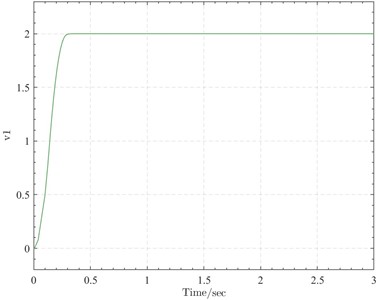
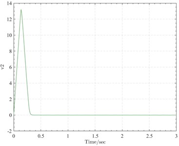
Fig. 2Variation of the second-order variable
Based on the classical second-order nonlinear TD, the TD design on SO(3) is given by:
where is the desired attitude.
3.2. Stability
Theorem Ⅰ: Concerning the system defined by
Proof: This theorem delineates a criterion for determining global asymptotic stability of nonlinear dynamic systems. It employs a positive definite function (commonly referred to as the Lyapunov function), hinging upon Lyapunov’s stability theory – a pivotal branch in control theory utilized for analyzing and designing control system stability [15].
(1) Positive Definiteness: The function tends to infinity as approaches infinity, implying that increases in all directions within the state space, particularly away from the origin. In other words, the larger the magnitude of the state variables, the greater the value of . This suggests that if the system state deviates from the origin (the equilibrium point), the value of correspondingly increases, embodying the concept of positive definiteness.
(2) Negative Derivative of the Lyapunov Function: Along the system trajectories, the time derivative of , denoted , is persistently negative (or non-positive in some cases, depending on the system and the analysis objective). This signifies that the system is “dissipating energy” at any non-equilibrium point, or equivalently, the system’s state consistently evolves toward a decrease in . Crucial to system stability, this indicates that the system will not indefinitely maintain states distant from zero but instead converges to an equilibrium state.
(3) Uniqueness: Apart from the equilibrium point at , there exists no other point for which . Thus, is the sole global minimum of . This assurance guarantees that all possible trajectories ultimately converge to this equilibrium point, as the system does not “halt” at any other point (reaching another local minimum).
By synthesizing these three conditions, it is deduced that the given system exhibits global asymptotic stability. Consequently, regardless of initial conditions (excluding the equilibrium point itself), the system's state progressively approaches and stabilizes at the origin . This characteristic is vital in control system design, as it ensures the system's long-term stable behavior.
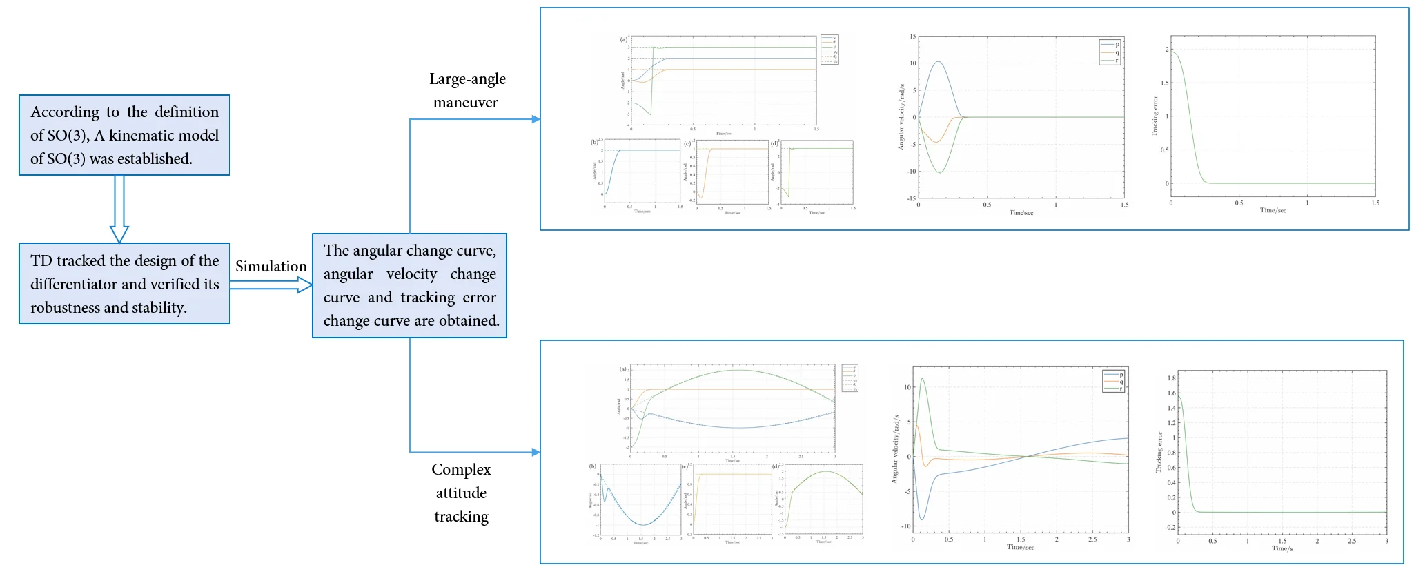
4. Simulation
To evaluate the attitude tracking performance of the tracking differentiator, a set of desired attitude angle data was inputted into each of the three attitude angle channels. By analyzing the tracking situation between the measured values and the desired values, the attitude tracking performance of the tracking differentiator can be obtained. To more realistically investigate the attitude tracking performance of the tracking differentiator, this work selects two sets of desired attitude angle data: large-angle maneuver and complex attitude tracking. The data is collected from an actual flight process of an unmanned aerial vehicle, providing results that are closer to the actual flight attitude tracking performance. The initial Euler angle values are set as rad, with set to 100 and set to 0.01.
4.1. Large-angle maneuver
The desired attitude is set as rad. Under the action of the tracking differentiator, the Euler angle curve and the desired and output angle curves for roll, pitch, and yaw are shown in (a), (b), (c), and (d) of Fig. 3 respectively.
From the analysis of Fig. 3, it can be seen that initially, the roll angle and pitch angle slightly decrease, and then both increase to the desired values of rad and rad at approximately 0.4 seconds. This tracking approach appears to be “seeking the distant before the near”, but it is actually the fastest tracking method, which will be analyzed and demonstrated in the subsequent tracking error variation curve Fig. 5. The yaw angle starts from –2 rad and reaches (i.e., ) at 0.2 seconds, and then attains the desired value of 3 rad at approximately 0.4 seconds. Therefore, during large-angle maneuvers, the tracking differentiator can achieve attitude angle tracking control for the duct-type unmanned aerial vehicle.
Fig. 3Angle variation curves: a) Euler angle curve, b) desired and measured roll angle curves, c) desired and measured pitch angle curves, d) desired and measured yaw angle curves
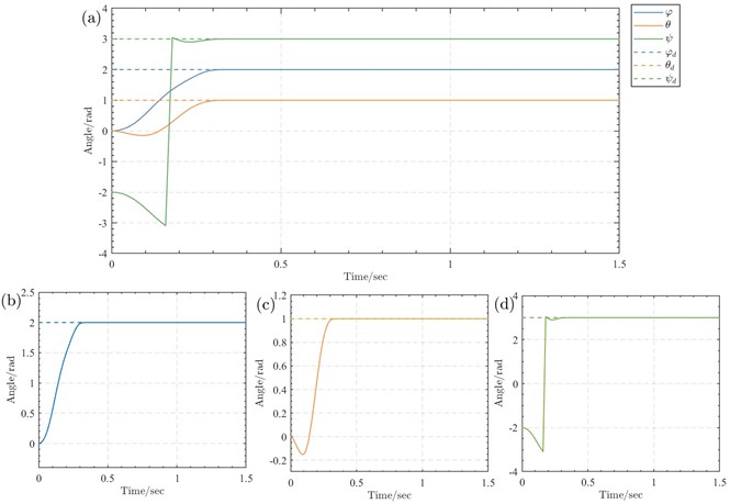
Fig. 4Angular velocity curves
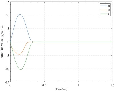
To reduce the tracking error to zero, the initial values of the angular velocities in all three directions were set to zero, and the dynamic variation plot is shown in Fig. 4. Around 0.3 seconds, the angular velocities in all three directions became zero again. Specifically, the roll angular velocity and pitch angular velocity both reached their extreme values of approximately 10.31 rad/s and –4.65 rad/s, respectively, at around 0.13 seconds, while the yaw angular velocity reached its minimum value of approximately –10.31 rad/s at around 0.16 seconds.
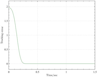
Fig. 5 shows the tracking error variation curve. The initial error was approximately 1.96, and the tracking error curve exhibited a smooth decreasing trend. At 0.3 seconds, the error decreased to 0.0004, which is nearly zero, and could be maintained within a small positive interval around zero. This explains the aforementioned “seeking the distant before the near” angle variation approach, which follows the shortest path to reach the desired attitude. In other words, the tracking differentiator can provide the shortest rotational path from the initial attitude to the target attitude.
Fig. 5Tracking error variation curve
4.2. Complex attitude tracking
The desired attitude was set as rad. Under the action of the tracking differentiator, the Euler angle curve and the desired and output angle curves for roll, pitch, and yaw are shown in (a), (b), (c), and (d) of Fig. 6, respectively.
Fig. 6Angle variation curves: a) Euler angle curve, b) desired and measured roll angle curves, c) desired and measured pitch angle curves, d) desired and measured yaw angle curves
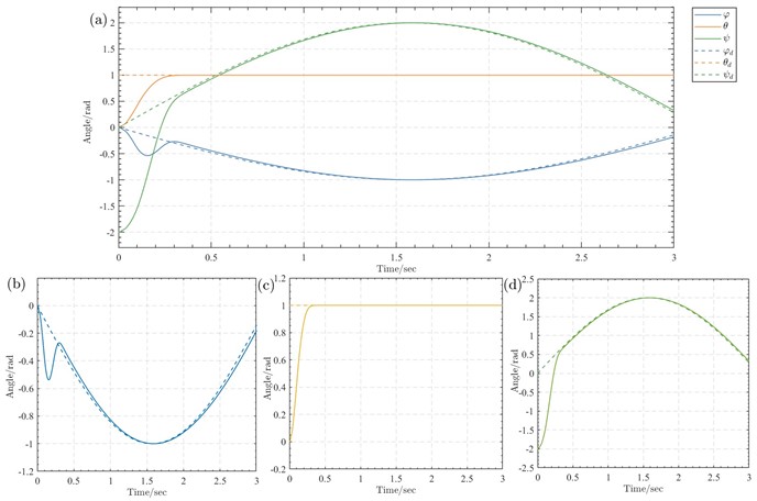
From the analysis of Fig. 6, it can be seen that initially, the roll angle first decreased and reached –0.54 rad at 0.15 seconds before increasing, and essentially attained the desired value after 0.3 seconds. The pitch angle steadily increased within the first 0.3 seconds and essentially reached the desired value of rad after 0.3 seconds. The yaw angle was initially set to –2 rad, steadily increased within the first 0.3 seconds, and essentially attained the desired value after 0.3 seconds. Therefore, during complex attitude tracking, the tracking differentiator could achieve attitude angle tracking control for the unmanned aerial vehicle.
Fig. 7Angular velocity curves
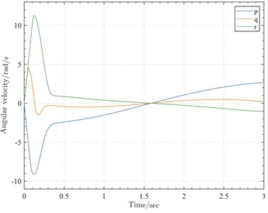
The dynamic variations of the angular velocities in three directions are depicted in Fig. 7. Around 0.3 seconds, the trends of the angular velocities in all three directions tend to stabilize. Specifically, the roll angular velocity reaches its minimum value of approximately –9.1 rad/s at around 0.13 seconds, followed by a sharp increase to its maximum value of 0.37 rad/s at 0.35 seconds, and subsequently exhibits a steady increase. The pitch angular velocity reaches its maximum value of approximately 4.51 rad/s at around 0.05 seconds, then rapidly decreases to its minimum value of –1.47 rad/s at 0.17 seconds, followed by a sharp increase to its maximum value of –0.29 rad/s at 0.31 seconds, and finally tends to flatten out. The yaw angular velocity reaches its maximum value of approximately 11.3 rad/s at around 0.13 seconds, then rapidly decreases to its minimum value of 0.98 rad/s at 0.37 seconds, and subsequently exhibits a steady decrease.
Fig. 8Tracking error variation curve
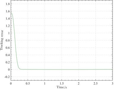
Fig. 8 illustrates the tracking error variation under complex attitude tracking. The initial error is approximately 1.55, similar to the case of large-angle maneuver. The tracking error curve exhibits a smooth decreasing trend, with the error decreasing to 0.004 at 0.3 seconds, which is nearly zero, and can be maintained within a small positive interval around zero. Therefore, this result further confirms that the tracking differentiator can provide the shortest rotational path from the initial attitude to the target attitude under more robust conditions.
5. Conclusions
To address the demand for high-precision attitude tracking in fields such as spacecraft attitude control, this work conducted an in-depth investigation of the theoretical foundations of SO(3) and so(3), deriving the kinematics model and error dynamics model of a rigid body on SO(3), thereby establishing the theoretical basis for the design of high-performance tracking differentiators on SO(3). Building upon the classical second-order nonlinear TD design method, a new second-order TD design method based on the SO(3) model was proposed. This method achieved improved dynamic performance and tracking accuracy by constructing a reasonable virtual control input on SO(3). Simulations and experiments validated the effectiveness and superiority of the designed TD under various conditions, including large-angle attitude tracking and complex attitude trajectory tracking. The results demonstrated that during large-angle maneuvers, the roll, pitch, and yaw angles could rapidly and smoothly converge to their respective desired values, with the initially large tracking error rapidly decreasing to nearly zero within a short period, proving the effectiveness of this method in achieving the fastest attitude tracking. In complex attitude tracking scenarios, the angles in all three directions could effectively track the expected time-varying trajectories, with the initial error decreasing to a small value within a short time and remaining within a small positive interval, exhibiting excellent tracking capability of the TD for complex trajectories. In summary, the new TD design method based on the SO(3) model proposed in this work can achieve high-precision and rapid tracking control for both large-angle and complex attitude maneuvers, possessing significant theoretical implications and prospects for engineering applications. It provides an effective technical solution for fields such as spacecraft attitude control and robotic operations.
References
-
J. Han and W. Wang, “Nonlinear tracking-differentiator,” Journal of Systems Science and Mathematical Sciences, Vol. 14, No. 2, pp. 177–183, 1994.
-
Q. Wen, M. Wang, X. Li, and Y. Chang, “Learning-based design optimization of second-order tracking differentiator with application to missile guidance law,” Aerospace Science and Technology, Vol. 137, p. 108302, Jun. 2023, https://doi.org/10.1016/j.ast.2023.108302
-
X. Tu, Y. Zhou, P. Zhao, and X. Cheng, “State estimation of a robot joint by a novel nonlinear tracking differentiator,” Industrial Robot: An International Journal, Vol. 45, No. 1, pp. 11–22, Jan. 2018, https://doi.org/10.1108/ir-08-2017-0149/full/html
-
H. Li, X. An, R. Feng, and Y. Chen, “Motion control of autonomous underwater helicopter based on linear active disturbance rejection control with tracking differentiator,” Applied Sciences, Vol. 13, No. 6, p. 3836, Mar. 2023, https://doi.org/10.3390/app13063836
-
Ben Guo, Liying Hu, and Yang Bai, “A nonlinear PID controller with tracking differentiator applying in BLDCM servo system,” in IEEE 7th International Power Electronics and Motion Control Conference (ECCE 2012), pp. 2467–2471, Jun. 2012, https://doi.org/10.1109/ipemc.2012.6259244
-
I. Aranda and G. Perez-Zuniga, “Highly maneuverable target tracking under glint noise via uniform robust exact filtering differentiator with intrapulse median filter,” IEEE Transactions on Aerospace and Electronic Systems, Vol. 58, No. 3, pp. 2541–2559, Jun. 2022, https://doi.org/10.1109/taes.2021.3138678
-
Z. Yang, J. Ji, X. Sun, H. Zhu, and Q. Zhao, “Active disturbance rejection control for bearingless induction motor based on hyperbolic tangent tracking differentiator,” IEEE Journal of Emerging and Selected Topics in Power Electronics, Vol. 8, No. 3, pp. 2623–2633, Sep. 2020, https://doi.org/10.1109/jestpe.2019.2923793
-
X. Shao, J. Liu, W. Yang, J. Tang, and J. Li, “Augmented nonlinear differentiator design,” Mechanical Systems and Signal Processing, Vol. 90, pp. 268–284, Jun. 2017, https://doi.org/10.1016/j.ymssp.2016.12.034
-
X. Shao, J. Liu, J. Li, H. Cao, C. Shen, and X. Zhang, “Augmented nonlinear differentiator design and application to nonlinear uncertain systems,” ISA Transactions, Vol. 67, pp. 30–46, Mar. 2017, https://doi.org/10.1016/j.isatra.2016.11.011
-
S. Liu, Z. Hou, Y. Guo, and L. Guo, “A novel modified robust model-free adaptive control method for a class of nonlinear systems with time delay,” in IEEE 8th Data Driven Control and Learning Systems Conference (DDCLS), pp. 1329–1334, May 2019, https://doi.org/10.1109/ddcls.2019.8908835
-
J. Li, R. Li, and H. Zheng, “Quadrotor modeling and control based on linear active disturbance rejection control,” in 35th Chinese Control Conference (CCC), pp. 10651–10656, Jul. 2016, https://doi.org/10.1109/chicc.2016.7555045
-
T. Lee, M. Leok, and N. H. Mcclamroch, “Geometric tracking control of a quadrotor UAV on SE(3),” in 49th IEEE Conference on Decision and Control (CDC 2010), pp. 5420–5425, Dec. 2010, https://doi.org/10.1109/cdc.2010.5717652
-
T. Fernando, J. Chandiramani, T. Lee, and H. Gutierrez, “Robust adaptive geometric tracking controls on SO(3) with an application to the attitude dynamics of a quadrotor UAV,” in 50th IEEE Conference on Decision and Control and European Control Conference (CDC-ECC 2011), pp. 7380–7385, Dec. 2011, https://doi.org/10.1109/cdc.2011.6161306
-
B.-Z. Guo and Z.-L. Zhao, “On convergence of tracking differentiator,” International Journal of Control, Vol. 84, No. 4, pp. 693–701, Apr. 2011, https://doi.org/10.1080/00207179.2011.569954
-
S. Tan, H. Lei, and P. Wang, “Design of tracking differentiator based on tangent Sigmoid function.,” Systems Engineering and Electronics, Vol. 41, No. 7, pp. 1590–1596, 2019, https://doi.org/10.3969/j.issn.1001-506x.2019.07.21
About this article

The authors have not disclosed any funding.
The datasets generated during and/or analyzed during the current study are available from the corresponding author on reasonable request.
Ruixin Deng: conceptualization, data curation, formal analysis, funding acquisition, investigation, methodology, software, validation, visualization, writing-original draft, writing-review and editing. Guolai Yang: supervision.
The authors declare that they have no conflict of interest.
