Abstract
In this paper, the bearing mechanical characteristics and thermal characteristics as it is running under constant speed (2400 r/min) and constant temperature (100 ℃) adopting bearing mechanical-thermal coupling model built on the basis of quasi-statics and elastohydrodynamic lubrication theory are discussed. Among which, the contact deformation between ball and inner/outer ring has same evolution law, besides, the same as the amplitude. Whose curve shape changes in the form of “circular-oblique D”, its amplitude rearches minimum value at 10thd3h between the location of 120° and 270°. The curve shapes belonging to contact angular between ball and inner/outer ring are similar to “circular”. There is opposite trend of them within the range of 90-300°. The amplitude of contact angular between ball and outer ring is the minimum at 10thd3h and 11thd1h. At the same time, the amplitude of that between ball and inner ring is the maximum. The evolution rules of contact stiffness between ball and inner/outer ring are generally consistent, which are similar to “crab”. But the amplitude of that between ball and outer ring is dominant. The maximum value of them occurs at 10thd3 and 11thd1h. The evolvement tendency of node temperatures maintains stable. Thereinto, the temperature of inner ring equals to that of contact location between ball and inner ring, which is the maximum value. It is obvious that ME, MD, MS, MCB, MCR and MOil devote themselves to heat production, the contribution rates of ME, MS, MCB and MCR are 100 %, the contribution rate of MD ranges from 52.6 % to 65.2 %. However, the amplitudes of friction moments have the opposite trend compared to “heat contribution factor”. The expansion amount owing to heat production is dominant in displacement variation and the effect of clearance on displacement can be ignored, whose evolution rules are contrary. The evolution rules of oil film thickness and oil film stiffness between ball and inner/outer ring are alike. Among which, the oil film thickness between ball and outer ring is dominant, its maximum value emerges at 10thd3h. The curve shapes of oil film stiffness between ball and outer/inner ring are oblique “D”, their amplitudes reach the maximum at 11thd1h-11thd3h.
Highlights
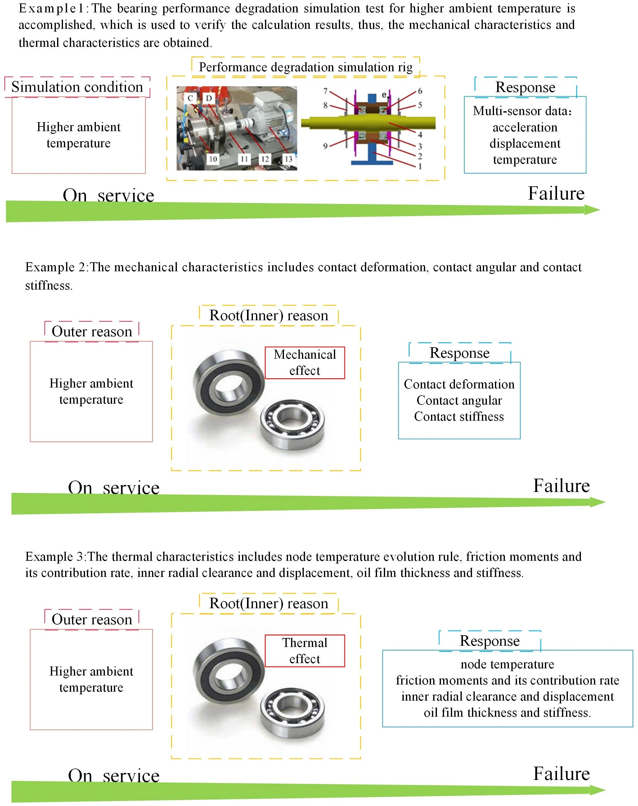
- The bearing performance degradation simulation test for higher ambient temperature is accomplished, which is used to verify the calculation results, thus, the mechanical characteristics and thermal characteristics are obtained.
- The mechanical characteristics includes contact deformation, contact angular and contact stiffness.
- The thermal characteristics includes node temperature evolution rule, friction moments and its contribution rate, inner radial clearance and displacement, oil film thickness and stiffness.
1. Introduction
The mechanism and law of higher ambient temperature acting on bearing service performance, especially on its mechanical and thermal characteristics as bearing is running are complex. Owing to the gap between ambient temperature during micro-turbine bearing is in motion and mounting temperature (i.e. room temperature), there are varying degrees of bearing parts expansion over the operation process of bearing, which results in diversification of working clearance and contact mode between rolling element and inner/outer ring. On the other hand, there is obvious variation of lubrication oil viscosity and oil film thickness thanks to larger temperature difference. Hence, a significant temperature gap would led to notable alteration of bearing inner contact characteristics and further exacerbate heat generation of the mating parts. Furthermore, the higher ambient temperature over the operation process of bearing blocks the diffusion of friction heat, thus, bearing inner temperature raises up, which causes the deterioration of bearing performance. It concretely represents as roller tempering, thermoelastic instability, even thermal runaway, which result in the occurrence of scuffing [6-10], burning up [1-3] and seizure [4-9]. Consequently, the thermal factors affecting the bearing as it is running include friction heat production and ambient heat.
Heat production modes of angular contact ball bearing are divided into 3 types, which are individually associated with load, viscosity, and spin [10, 11]. The reason that bearing failure affected by thermal factor is thermal induced preload that is the material expansion of bearing parts due to friction heat production, which changes the contact characteristics between the mating parts and influences the bearing performance execrably [12].
It can be seen that the existing researches mainly focus on the instant contact characteristics of bearing influenced by inner friction heat generation due to rotation speed, preload, improper installation and so on. Wu [13] et al. advocated that the influence of non-uniform preload acting on the bearing heat production and heat distribution, it is obvious that the non-uniform preload not only decreases the heat production, but relieves heat concentration, makes the maximum value of temperature as bearing is running cut down. Yan [14] et al. illustrated that the influence of multiple working conditions and structure parameters on the bearing thermal properties based on local method and elastohydrodynamic lubrication theory, which proves that there is obvious heat production in raceway, it is dominant in heat production of bearing. Than [15] et al. played the emphasis on nonlinear thermal effect owing to preload, it explains that the friction heat has significant effect on contact load but little influence on contact angular. Li [16] et al. presented that the bigger tilt angle of outer ring is, the more contact angular and contact load is, the more heat production is and the higher outer ring temperature is. Neisi [17] et al. mainly focused on the effect of surface waviness on the bearing heat generation and inner contact characteristics, the result proves that the temperature rise is affected by rotation speed of inner ring, viscosity of lubrication oil and friction coefficient. The bigger the amplitude of waviness is, the higher the heat production and contact load between ball and ring are, however, there is little influence of waviness order on heat production. Su [18] et.al. discussed the thermal behavior of bearing under oil-air lubrication considering the thermal-mechanical coupling effect, it is evident that contact load and contact deformation increase with the development of rotation speed, besides, the rotation speed has more serious effect on oil film thickness than that of contact load, oil film thickness has more and more influence on distance between ring curvature center and ball center with increment of rotation speed.
However, the heat dissipation is blocked due to higher ambient temperature over the operation process of micro-turbine bearing. Moreover, the higher ambient temperature gives rise to expansion of the mating parts in different degrees, thus, it aggravates inner heat generation of bearing, which results in significant change of bearing inner mechanical properties and thermal properties during the continuous degradation process of bearing, the related researches are rarely reported.
In this paper, the mechanical characteristics and thermal characteristics affected by inner abnormal thermal effect owing to higher ambient temperature are studied. Firstly, the ambient temperature simulation principle is introduced. The corresponding bearing performance simulation test on the basis of micro-turbine bearing-rotor rig are executed, as a consequence, the temperature and acceleration signals over the whole life of bearing are obtained. Secondly, the mechanical characteristics and thermal characteristics evolution laws over the whole life of bearing under higher ambient temperature are analytical analyzed via modifying “heat contribution factor”, whose calculation accuracy is validated by test signal of temperature.
The structure of the following paper is illustrated: In Section 2, the simulation principle and method are described. Section 3 illustrates test rig for micro-turbine bearing performance simulation. In Section 4 analyzes and discusses the results. A conclusion is made in Section 5.
2. Higher ambient temperature simulation principle and method
This test is employed to simulate transfer process along the route of volute-house-bearing for heat quantity of micro-turbine air supply with high temperature during the operation process of bearing. As illustrated in Fig. 1(a), the higher ambient temperature is obtained by adopting built-in heating system to heat bearing outer ring.
The specific way is shown as follows: house end is evenly punched along circumference direction, which is filled with 6 dry heat rods illustrated in Fig. 1(b), after the rods are fixed, it directly contact with outer ring. The power of dry heat rod is 20 W, it is equivalent to total 120 J of heat quality per second delivered from environment to house along circumference direction.
Fig. 1Heating mechanism
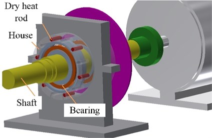
a) Schematic diagram of the heating mode
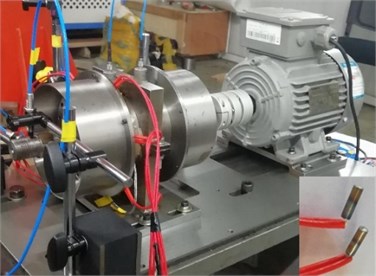
b) Physical diagram of the heating mode
The bearing mechanical-thermal coupling model illustrated in the paper [19] is used to analyze the mechanical and thermal characteristics affected by higher ambient temperature, whose accuracy is verified by the comparison between house temperature calculation value and test value. Among which, node thermal network model of tested bearing is illustrated in Fig. 2. Ignoring the seal and chamfer angular, the bearing is divided into 17 nodes. There are 7 nodes in bearing body and 4 nodes in different locations of shaft. Besides, the external environment is 1 node. Node name and meaning is illustrated in Table 1.
Fig. 2Node thermal network model
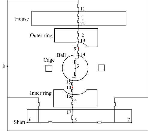
Finally, it is necessary to add up additional heat term 120 J to node 1 when stationary temperature field is calculated by utilizing bearing mechanical-thermal coupling model.
Table 1Description of nodes arrangement
Node No. | Location |
1 | House |
2 | Outer ring |
3 | Ball |
4 | Inner ring |
5, 6, 7 | Shaft |
8 | Air |
9, 10 | Contact zone between ball and outer/inner ring |
11 | External surface of house |
12 | House surface contacting with outer ring |
13 | Inner surface of outer ring |
14, 15 | Ball surface contacting with outer/inner ring |
16 | Outer surface of inner ring |
17 | Shaft surface contacting with inner ring |
In order to obtain the friction moment in different phases of bearing and satisfactory temperature field calculation results, the “heat contribution factor” is proposed to modify the load friction moment and viscosity friction moment proposed by Palmgren [20, 21] when bearing stationary temperature field is calculated based on mechanical-thermal coupling model. The expression is shown as follows:
where, ζ*(*=E,D,S,CB,CR,Oil) is “heat contribution factor” that is the parameter considering bearing friction location and severity synthetically. ME is the friction moment due to elastic hysteresis. MD is the friction moment due to differential sliding motion. MS is the friction moment induced by spin-sliding motion. MCB is the friction moment due to the contact between cage and ball. MCR is the friction moment due to the contact between cage and inner ring guide face. MOil is the friction moment due to the loss of oil film viscosity.
3. Test rig
3.1. Higher ambient temperature simulation test rig
The multi-sensor data during the operation process of bearing standing higher ambient temperature is acquired on the basis of micro-turbine bearing-rotor system test rig [22], as depicted in Fig. 3, the rotor coupled to the AC motor is upheld by angular contact ball bearing locating at C, D. Among which, the bearing locating at C is tested bearing, the other is contact bearing. The rig has the ability of operation at any speed. The bearings fixed in the tube-shaped house by means of end covers, whose number is 6 and 7, respectively. The house is connected to the pedestal via interference fit at the middle of it, whose number is 2. Besides, 1 is the number of pedestal, 3, 9 are the number of end cover, 4 is the number of shaft, 5, 8 are the number of disc, 10, 11 are the number of drum, 12 is the number of coupling, 13 is number of motor.
3.2. Test system
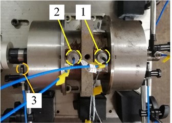
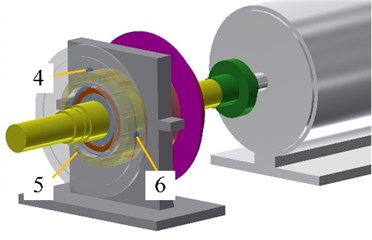
The bearing is under operation with speed 2400 r/min, whose vibration has obvious enlargement means that the bearing failure. The whole life of bearing is the overall process until bearing failure. As illustrated in Fig. 4, the vibration signal of two bearings is recorded adopting CAYD115V-100A IEPE accelerometer individually fixed on the 1, 2 of house. RP6606XL eddy current sensor fixed near motor is utilized to measure shaft displacement, which has the number of 3 and can indicate shaft speed. Thermal couple with the number of 4-6 are mounted evenly around circumference direction of house, sensor 4 is located forming 15 degree with vertical direction for avoiding the influence of bearing vibration test. Besides, a National Instrument compact Data Acquisition (NI Cdaq-9174) programmed with NI LabVIEW software is employed to record and real-time display the signal. The record mode is continuous, sampling frequency of vibration signal is 25.6 Hz, sampling frequency of temperature is 2 Hz, sampling period is 20 s.
Fig. 3Test equipment
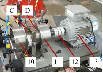
a) Test rig
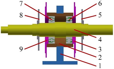
b) Rotor structure
Fig. 4Position of transducers
4. Results and discussion
Bearing is heated when rotation speed keeps at 2400 r/min, average temperature of 3 test points is about 100 ℃ after 1 hour. The test lasts 11 days, 4 hours per day, among which, it is 3 hours for running at stable temperature (100 ℃). At the last day, the acceleration amplitude of tested bearing reaches about 25 g.
As depicted in Fig. 5, house temperature calculation value has high consistency with the mean test value of 3 points. In addition, MAPEt= 0.45 % [23], which verify the accuracy of calculation value obtained by the bearing mechanical-thermal coupling model.
The bearing mechanical characteristics and thermal characteristics as its performance is deteriorating under higher ambient temperature are shown as follows.
4.1. Mechanical characteristic evolution rules analysis
As bearing is running, bearing inner mechanical characteristics of the mating parts express complicated due to the parts have different degrees of expansion affected by friction heat production under higher ambient temperature, which includes contact deformation, contact angular and contact stiffness.
Fig. 5Temperature evolution rule of house temperature under stable ambient temperature
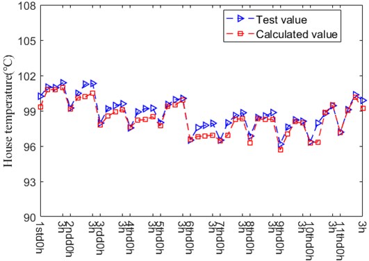
Fig. 6Contact deformation
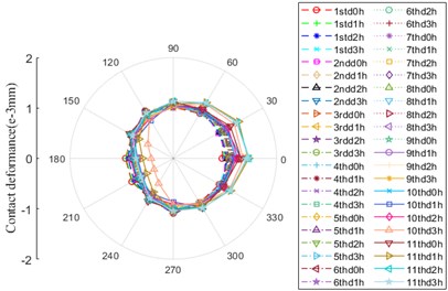
a) Contact location between ball and outer ring
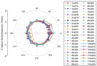
b) Contact location between ball and inner ring
As depicted in Fig. 6, there are contact deformation between ball and inner/outer ring under the action of higher ambient temperature, which has the same evolution law in the whole life of bearing, besides, the same as the amplitude. During the operation process of bearing, the shape of drawing maintains “circular” for most of the service time. At 10th day (10thd0h), it begins to change and gradually shows an oblique "D" shape with a deviation to the position of 0° and 30°. Between the location of 120° and 270°, the amplitude is minimum at 10thd3h.
Fig. 7Contact angular
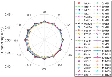
a) Contact location between ball and outer ring
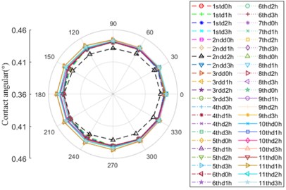
b) Contact location between ball and inner ring
The contact angular evolution curves between ball and inner/outer ring are shown in Fig. 7. Over the whole life of bearing, their shapes are similar to “circular”. The disparity of them is mainly within the range of 90-300°, whose trend is opposite. According to the variation trend, the evolution curve can be divided into 3 stages: 10thd3h and 11thd1h, 11thd0h, 11thd2h and 11thd3h. For example, at 10thd3h and 11thd1h, the amplitude of contact angle between ball and outer ring is minimum value as the bearing is under operation, meanwhile, the amplitude of that between ball and inner ring is the maximum, which rearches minimum value at 2ndd2h. Nevertheless, the value of contact angle between ball and outer ring increases at 11thd2h and decreases to the minimum value at 11thd1h, next, it continues to grow up, the amplitude at 11thd3h is slightly less than that at 10thd2h.
Fig. 8Contact stiffness
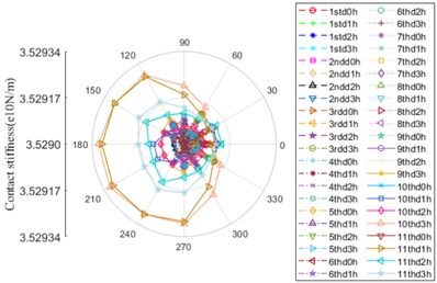
a) Contact location between ball and outer ring
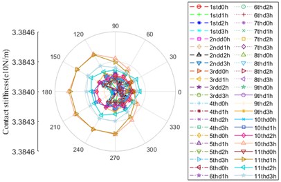
b) Contact location between ball and inner ring
As illustrated in Fig. 8, the evolution rules of contact stiffness between ball and inner/outer ring are generally consistent, which are similar to “crab”, but the value of contact stiffness between ball and outer ring is dominant on the whole. The zone that the amplitude evidently fluctuates ranges from 60° to 300°. The maximum amplitude is at 10thd3 and 11thd1h, both of which are generally equal, however, the amplitude decreases to minimum value at 11thd0h, then it starts to lift up until the maximum, after that, it continuous to decrease (11thd2h), there is an apparent enlargement at the last moment (11thd3h).
4.2. Thermal characteristic evolution rules analysis
The bearing properties corresponding to thermal effect are node temperature evolution rule, friction moments and its contribution rate, inner radial clearance and displacement, oil film thickness and stiffness.
Node temperature calculation value curves of bearing system under higher ambient temperature are illustrated in Fig. 9. The temperature value of each node keeps stable, among them, the temperature of inner ring is equal to that of contact location between ball and inner ring, which is the maximum value. The temperature of inner ring is approximately equal to that of shaft right end. However, the temperature of contact zone between ball and outer ring is lightly larger than that of outer ring.
The friction moments growing out of the mating parts over the whole life of bearing under higher ambient temperature are shown in Fig. 10, which are the friction moment caused by elastic hysteresis ME, the friction moment caused by differential sliding motion MD, the friction moment caused by spin-sliding motion MS, the friction moment caused by the contact between cage and ball MCB, the friction moment caused by the contact between cage and inner ring guide face MCR and the friction moment caused by the loss of oil film viscosity MOil, respectively. It is obvious that each friction moment basically maintains steady, among which, MD and MCR are dominant, whose value are almost same. However, MS, MCB and MOil can be ignored.
Fig. 9The temperature evolution curve of bearing system nodes over whole lifetime
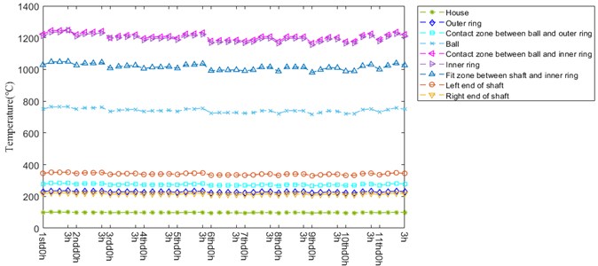
Fig. 10Friction moment
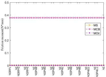
a)
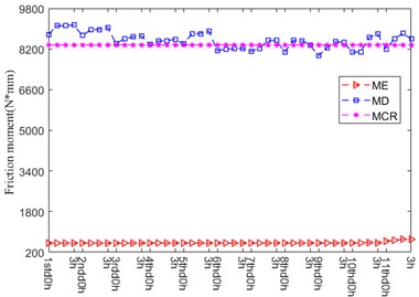
b)
The “heat contribution factor” corresponding to the different moments over the whole life of bearing under higher ambient temperature are illustrated in Table 2. It shows that all of the friction pairs have contribution to heat production of bearing. Among which, the contribution rates of ME, MS, MCB, MCR and MOil are 100 %, which keep steady over the whole life of bearing. However, the contribution rate of MD ranges from 52.6 % to 65.2 %, whose maximum value and minimum value are individually at 10thd3h and 11thd0h. According to the “heat contribution factor” variation of MD, the whole life of bearing is separated into 2 phases: 1thd0h-5thd3h and 6thd0h-11thd3h. In the first phase, the values of “heat contribution factor” are almost greater than 60 % or approximately equal to 60 % (except 3rdd1h). The values of “heat contribution factor” are totally smaller than 60 % in the second phase.
Fig. 11 depicts the radial clearance and displacement curve during the operation process of bearing, which is generally divided into 2 stages: 1std0h-6thd0h and 6thd0h-11thd3h. As illustrated in Fig. 11(a), the clearance value largely fluctuates and generally raises up. However, the calculation value of displacement maintains steady on the whole. The difference between clearance and displacement is 1 order of magnitude, so it has little contribution to displacement. In other words, the expansion amount owing to heat production is dominant in displacement variation and has the tendency of fluctuation and decrement. Besides, it can be seen that the variation trend of clearance is negatively correlated with the temperature, while the variation trend of displacement is positively correlated with the temperature. The clearance value owning an increasing trend of fluctuation is negative. The difference between measured displacement value and calculated displacement value keeps basically stable in the whole operation process of bearing. The reason that the difference is large is the influence of temperature variation on fit between shaft and inner ring, fit between house and outer ring, deformation of shaft and house is without consideration.
Table 2Heat contribution factor
Friction moment | 1std 0h | 1std 1h | 1std 2h | 1std 3h | 2ndd 0h | 2ndd 1h | 2ndd 2h | 2ndd 3h | 3rdd 0h | 3rdd 1h | 3rdd 2h |
ME | 1 | 1 | 1 | 1 | 1 | 1 | 1 | 1 | 1 | 1 | 1 |
MS | 1 | 1 | 1 | 1 | 1 | 1 | 1 | 1 | 1 | 1 | 1 |
MCB | 1 | 1 | 1 | 1 | 1 | 1 | 1 | 1 | 1 | 1 | 1 |
MOil | 1 | 1 | 1 | 1 | 1 | 1 | 1 | 1 | 1 | 1 | 1 |
MCR | 1 | 1 | 1 | 1 | 1 | 1 | 1 | 1 | 1 | 1 | 1 |
MD | 0.612 | 0.64 | 0.64 | 0.642 | 0.61 | 0.628 | 0.63 | 0.638 | 0.548 | 0.6 | 0.608 |
Friction moment | 3rdd 3h | 4thd 0h | 4thd 1h | 4thd 2h | 4thd 3h | 5thd 0h | 5thd 1h | 5thd 2h | 5thd 3h | 6thd 0h | 6thd 1h |
ME | 1 | 1 | 1 | 1 | 1 | 1 | 1 | 1 | 1 | 1 | 1 |
MS | 1 | 1 | 1 | 1 | 1 | 1 | 1 | 1 | 1 | 1 | 1 |
MCB | 1 | 1 | 1 | 1 | 1 | 1 | 1 | 1 | 1 | 1 | 1 |
MOil | 1 | 1 | 1 | 1 | 1 | 1 | 1 | 1 | 1 | 1 | 1 |
MCR | 1 | 1 | 1 | 1 | 1 | 1 | 1 | 1 | 1 | 1 | 1 |
MD | 0.608 | 0.584 | 0.594 | 0.597 | 0.599 | 0.584 | 0.615 | 0.62 | 0.631 | 0.563 | 0.566 |
Friction moment | 6thd 2h | 6thd 3h | 7thd 0h | 7thd 1h | 7thd 2h | 7thd 3h | 8thd 0h | 8thd 1h | 8thd 2h | 8thd 3h | 9thd 0h |
ME | 1 | 1 | 1 | 1 | 1 | 1 | 1 | 1 | 1 | 1 | 1 |
MS | 1 | 1 | 1 | 1 | 1 | 1 | 1 | 1 | 1 | 1 | 1 |
MCB | 1 | 1 | 1 | 1 | 1 | 1 | 1 | 1 | 1 | 1 | 1 |
MOil | 1 | 1 | 1 | 1 | 1 | 1 | 1 | 1 | 1 | 1 | 1 |
MCR | 1 | 1 | 1 | 1 | 1 | 1 | 1 | 1 | 1 | 1 | 1 |
MD | 0.568 | 0.569 | 0.562 | 0.571 | 0.598 | 0.599 | 0.558 | 0.599 | 0.599 | 0.599 | 0.546 |
Friction moment | 9thd 1h | 9thd 2h | 9thd 3h | 10thd 0h | 10thd 1h | 10thd 2h | 10thd 3h | 11thd 0h | 11thd 1h | 11thd 2h | 11thd 3h |
ME | 1 | 1 | 1 | 1 | 1 | 1 | 1 | 1 | 1 | 1 | 1 |
MS | 1 | 1 | 1 | 1 | 1 | 1 | 1 | 1 | 1 | 1 | 1 |
MCB | 1 | 1 | 1 | 1 | 1 | 1 | 1 | 1 | 1 | 1 | 1 |
MOil | 1 | 1 | 1 | 1 | 1 | 1 | 1 | 1 | 1 | 1 | 1 |
MCR | 1 | 1 | 1 | 1 | 1 | 1 | 1 | 1 | 1 | 1 | 1 |
MD | 0.568 | 0.596 | 0.596 | 0.56 | 0.566 | 0.597 | 0.652 | 0.526 | 0.558 | 0.546 | 0.532 |
Fig. 11Radial clearance and displacement
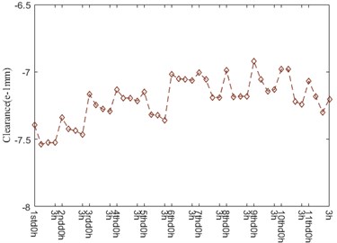
a) Radial clearance
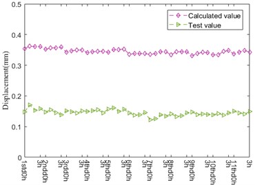
b) Radial displacement
As depicted in Fig. 12, the variation trend of oil film thickness between ball and inner/outer ring is alike, the chief fluctuation zone ranges from 150° to 240°, the oil film thickness between ball and outer ring is dominant. The oil film thickness run up to the maximum at 10thd3h, then it successively declines.
It can be seen from Fig. 13 that the oil film stiffness at contact location between ball and inner/outer rings has the same evolvement law. In the early service stage of bearing, the shape of curves presents itself in the form of oblique “D”, which has the slight difference in amplitude. With the degradation of bearing performance, the oil film stiffness ranging from 330° to 60° begins to increase at 10thd2h up to maximum at 11thd1h-11thd3h.
Fig. 12Oil film thickness
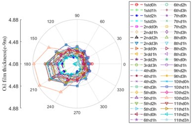
a) Contact location between ball and outer ring
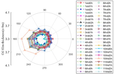
b) Contact location between ball and inner ring
Fig. 13Oil film stiffness
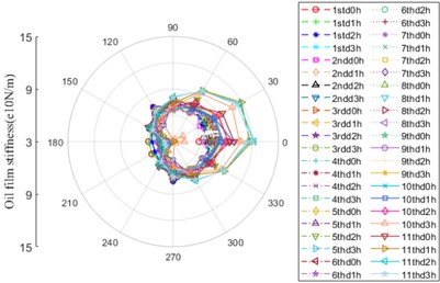
a) Contact location between ball and outer ring
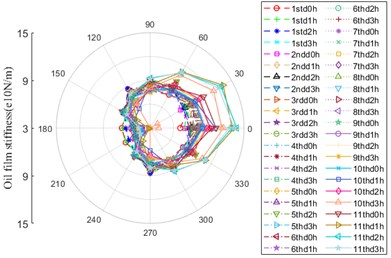
b) Contact location between ball and inner ring
5. Conclusions
In this paper, the bearing mechanical characteristics and thermal characteristics as it is running under constant speed (2400 r/min) and constant temperature (100 ℃) adopting bearing mechanical-thermal coupling model built on the basis of quasi-statics and elastohydrodynamic lubrication theory are discussed. The conclusions are made as follows:
1) The contact deformation between ball and inner/outer ring resulted from higher ambient temperature has same evolution law in the whole life of bearing, besides, the same as the amplitude. Whose curve shape maintains “circular” for most of the service time. At 10th day (10thd0h), it begins to change and gradually shows an oblique “D” shape with a deviation to the position of 0° and 30°. Between the location of 120° and 270°, the amplitude is minimum at 10thd3h. The curve shapes belonging to contact angular between ball and inner/outer ring are similar to “circular”. The disparity of them is mainly within the range of 90-300°, whose trend is opposite. Which is divided into 3 stages: 10thd3h and 11thd1h, 11thd0h, 11thd2h and 11thd3h. At 10thd3h and 11thd1h, the amplitude of contact angle between ball and outer ring is minimum value, meanwhile, the amplitude of that between ball and inner ring is the maximum, which rearches minimum value at 2ndd2h. The evolution rules of contact stiffness between ball and inner/outer ring are generally consistent, which are similar to “crab”, but the value of contact stiffness between ball and outer ring is dominant on the whole. The zone that the amplitude evidently fluctuates ranges from 60° to 300°. The maximum amplitude is at 10thd3 and 11thd1h, both of which are generally equal, however, the amplitude decreases to minimum value at 11thd0h, then it starts to lift up until the maximum, after that, it continuous to decrease (11thd2h), there is an apparent enlargement at the last moment (11thd3h).
2) The temperature value of each node keeps stable, among them, the temperature of inner ring is equal to that of contact location between ball and inner ring, which is the maximum value. The temperature of inner ring is approximately equal to that of shaft right end. However, the temperature of contact zone between ball and outer ring is lightly larger than that of outer ring. During the operation process of bearing under higher ambient temperature, ME, MD, MS, MCB, MCR and MOil devote themselves to heat production. Thereinto, the contribution rates of ME, MS, MCB, MCR and MOil are 100 %, the contribution rate of MD ranges from 52.6 % to 65.2 %. However, the amplitudes of friction moments have the opposite trend compared to “heat contribution factor”. According to the amplitude of friction moment, MD and MCR are dominant in the process of heat generation, MS, MCB and MOil can be ignored. The expansion amount owing to heat production is dominant in displacement variation and the effect of clearance on displacement can be ignored. Besides, the trend of clearance is negatively correlated with the temperature, while that of displacement is positively correlated with the temperature. The evolution rules of oil film thickness and oil film stiffness between ball and inner/outer ring are alike. Among which, the chief fluctuation zone of oil film thickness ranges from 150° to 240°, the oil film thickness between ball and outer ring is dominant. The oil film thickness run up to the maximum at 10thd3h, then it successively declines. However, in the early stage, the shape of curves corresponding to oil film stiffness presents itself in the form of oblique “D”, which has the slight difference in amplitude. From now on, the oil film stiffness ranging from 330° to 60° begins to increase at 10thd2h up to maximum at 11thd1h-11thd3h.
3) The reason that the difference between measured displacement value and calculated displacement value is large is the influence of temperature variation on fit between shaft and inner ring, fit between house and outer ring, deformation of shaft and house is without consideration.
In my opinion, although some satisfactory conclusions are made in the paper, there is a number of room for improvement in this work. The effect of heat production during the operation process of bearing under constant ambient temperature on fit between shaft and inner ring, fit between house and outer ring, deformation of shaft and house should be considered, thus, the uniformity between the calculation value of displacement and the test value of that could be improved. Besides, the working conditions of micro-turbine bearing are complex, such as rapid varying speed and ambient temperature. The paper studies the mechanical characteristics and thermal characteristics of bearing affected by constant speed and constant ambient temperature due to the run-to-failure under this condition costs long time. So, in the future work, the tests under different speed and ambient temperature should by conducted in order to obtain more approving and innovative results.
References
-
M. M. Khonsari and S. H. Wang, “On the role of particulate contamination in scuffing failure,” Wear, Vol. 137, No. 1, pp. 51–62, Apr. 1990, https://doi.org/10.1016/0043-1648(90)90017-5
-
M. M. Khonsari, M. D. Pascovici, and B. V. Kucinschi, “On the scuffing failure of hydrodynamic bearings in the presence of an abrasive contaminant,” Journal of Tribology, Vol. 121, No. 1, pp. 90–96, Jan. 1999, https://doi.org/10.1115/1.2833816
-
M. D. Pascovici and M. M. Khonsari, “Scuffing failure of hydrodynamic bearings due to an abrasive contaminant partially penetrated in the bearing over-layer,” Journal of Tribology, Vol. 123, No. 2, pp. 430–433, Apr. 2001, https://doi.org/10.1115/1.1329877
-
J. Takabi and M. M. Khonsari, “On the thermally-induced seizure in bearings: A review,” Tribology International, Vol. 91, pp. 118–130, Nov. 2015, https://doi.org/10.1016/j.triboint.2015.05.030
-
J. Yang, M. Li, and F. Ding, Practical Diagnosis Technology of Rolling Bearing in Field. (in Chinese), Beijing: China Machine Press, 2015.
-
C. Dellacorte, V. Lukaszewicz, M. J. Valco, K. C. Radil, and H. Heshmat, “Performance and durability of high temperature foil air bearings for oil-free turbomachinery,” Tribology Transactions, Vol. 43, No. 4, pp. 774–780, Jan. 2000, https://doi.org/10.1080/10402000008982407
-
K. Radil, S. Howard, and B. Dykas, “The role of radial clearance on the performance of foil air bearings,” Tribology Transactions, Vol. 45, No. 4, pp. 485–490, Jan. 2002, https://doi.org/10.1080/10402000208982578
-
Z.-C. Peng and M. M. Khonsari, “A thermohydrodynamic analysis of foil journal bearings,” Journal of Tribology, Vol. 128, No. 3, pp. 534–541, Jul. 2006, https://doi.org/10.1115/1.2197526
-
J. Takabi and M. M. Khonsari, “On the thermally-induced failure of rolling element bearings,” Tribology International, Vol. 94, pp. 661–674, Feb. 2016, https://doi.org/10.1016/j.triboint.2015.10.004
-
A. Zahedi and M. R. Movahhedy, “Thermo-mechanical modeling of high speed spindles,” Scientia Iranica, Vol. 19, No. 2, pp. 282–293, Apr. 2012, https://doi.org/10.1016/j.scient.2012.01.004
-
X. Hao, X. Yun, and Q. Han, “Thermal-fluid-solid coupling in thermal characteristics analysis of rolling bearing system under oil lubrication,” Journal of Tribology, Vol. 142, No. 3, pp. 1–12, Mar. 2020, https://doi.org/10.1115/1.4045377
-
C. Jin, B. Wu, and Y. Hu, “Heat generation modeling of ball bearing based on internal load distribution,” Tribology International, Vol. 45, No. 1, pp. 8–15, Jan. 2012, https://doi.org/10.1016/j.triboint.2011.08.019
-
W. Wu, X. Li, F. Xu, J. Hong, and Y. Li, “Investigating effects of non-uniform preload on the thermal characteristics of angular contact ball bearings through simulations,” Proceedings of the Institution of Mechanical Engineers, Part J: Journal of Engineering Tribology, Vol. 228, No. 6, pp. 667–681, Jun. 2014, https://doi.org/10.1177/1350650114524185
-
K. Yan, N. Wang, Q. Zhai, Y. Zhu, J. Zhang, and Q. Niu, “Theoretical and experimental investigation on the thermal characteristics of double-row tapered roller bearings of high speed locomotive,” International Journal of Heat and Mass Transfer, Vol. 84, pp. 1119–1130, May 2015, https://doi.org/10.1016/j.ijheatmasstransfer.2014.11.057
-
V.-T. Than and J. H. Huang, “Nonlinear thermal effects on high-speed spindle bearings subjected to preload,” Tribology International, Vol. 96, pp. 361–372, Apr. 2016, https://doi.org/10.1016/j.triboint.2015.12.029
-
X. Li, Y. Lv, K. Yan, J. Liu, and J. Hong, “Study on the influence of thermal characteristics of rolling bearings and spindle resulted in condition of improper assembly,” Applied Thermal Engineering, Vol. 114, pp. 221–233, Mar. 2017, https://doi.org/10.1016/j.applthermaleng.2016.11.194
-
N. Neisi, J. E. Heikkinen, and J. Sopanen, “Influence of surface waviness in the heat generation and thermal expansion of the touchdown bearing,” European Journal of Mechanics – A/Solids, Vol. 74, pp. 34–47, Mar. 2019, https://doi.org/10.1016/j.euromechsol.2018.10.014
-
C. Su and W. Chen, “Thermal behavior on motorized spindle considering bearing thermal deformation under oil-air lubrication,” Journal of Manufacturing Processes, Vol. 72, pp. 483–499, Dec. 2021, https://doi.org/10.1016/j.jmapro.2021.10.041
-
X. Yun, Q. Han, B. Wen, and X. Hao, “Dynamic stiffness and vibration analysis model of angular contact ball bearing considering vibration and friction state variation,” Journal of Vibroengineering, Vol. 24, No. 2, pp. 221–255, Mar. 2022, https://doi.org/10.21595/jve.2021.22196
-
A. Palmgren, Ball and Roller Bearing Engineering. Philadelphia: SKF Industries Inc, 1959.
-
K. Zhang and J. Li, “Friction moment analysis calculation for ball bearing,” (in Chinese), Bearing, Vol. 1, pp. 8–11, 2001.
-
X. Yun, N. Li, B. Wen, and Q. Han, “Study on stiffness of angular contact ball bearing and its evolution rule under excessive preload,” IOP Conference Series: Materials Science and Engineering, Vol. 1081, No. 1, p. 012012, Feb. 2021, https://doi.org/10.1088/1757-899x/1081/1/012012
-
R. Fernandez Martinez, R. Lostado Lorza, A. A. Santos Delgado, and N. O. Piedra Pullaguari, “Optimizing presetting attributes by softcomputing techniques to improve tapered roller bearings working conditions,” Advances in Engineering Software, Vol. 123, pp. 13–24, Sep. 2018, https://doi.org/10.1016/j.advengsoft.2018.05.005
About this article
This research work was supported by the National Key R&D Program of China (Grant No. 2018YFB2000300).

