Abstract
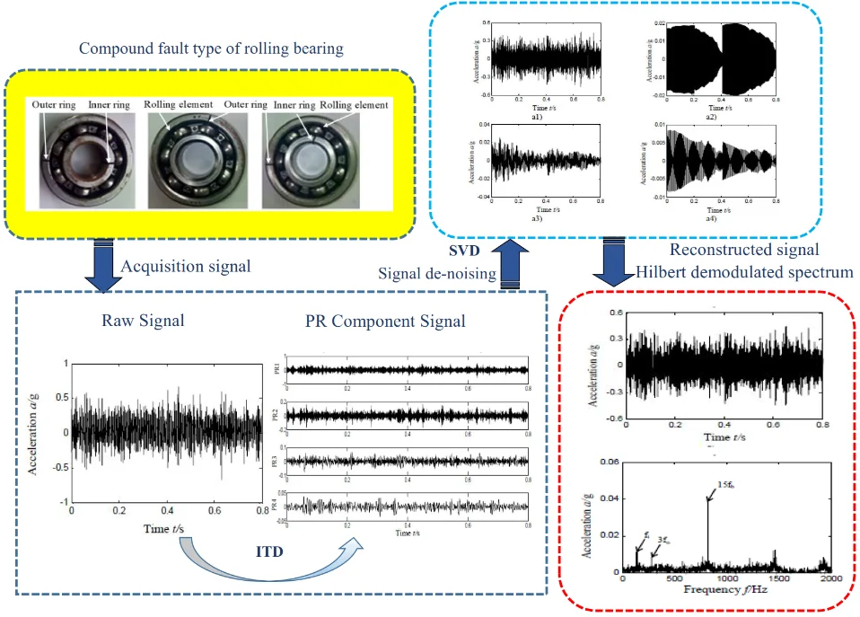
Considering the difficulty in the diagnosis of compound faults in rolling bearings, the paper combines Intrinsic Time-scale Decomposition (ITD) and Singular Value Decomposition (SVD) for extracting the characteristics of compound faults from rolling bearings. Rotational components obtained from ITD decomposition are denoised according to Singular Value Decomposition algorithm; signal is reconstructed by denoised rotational components; at last, characteristics of compound faults of rolling bearings are extracted by Hilbert spectrum envelope of reconstructed signal. In validation, the paper has made a comparative study on the proposed ITD-SVD method and conventional one based on ITD algorithm and PCA method, and the result shows that ITD-SVD method works better on noise control and thereby provides more precise extraction of characteristic frequency of compound faults from rolling bearings of aero-engine.
Highlights
- ITD signal decomposition algorithm is used to decompose the rolling bearing composite fault signal.
- Rotational components obtained from ITD decomposition are denoised according to Singular Value Decomposition algorithm.
- Signal is reconstructed by denoised rotational components.
- The research has made a comparative study on the proposed ITD-SVD method and conventional one based on ITD algorithm and PCA method.
1. Introduction
It is of great significance to make fault diagnosis of rolling bearings, one of the important and vulnerable parts in large-sized rotary machines like aero-engine [1]. As vibration signal of rolling bearings are nonlinear and non-stationary [2], conventional time domain [3, 4] and frequency-domain analysis [5, 6] is difficult to extract compound fault signal. Time-frequency domain analysis can provide both time domain and frequency domain information and has been widely applied to the fault diagnosis of rolling bearings [7]. Typical time-frequency analysis consists of wavelet transform [8], short-time Fourier transform [9], Hilbert Huang transform [10], Empirical Mode Decomposition (EMD) [7, 11] and so on. As proved by the studies on engineering practice, faults of rolling bearings are present as compound faults in most of cases and characteristic extraction has been proved to be far more difficult than signal fault’s [12]. Tang proposed the extraction method based on improved harmonic wavelet packet decomposition [13]; Hu proposed a resonance demodulation method based on correlative peak and applied it to the characteristic extraction of compound faults in rolling bearings [14].
In 2006, FREI, et al provided a self-adaptive time-frequency method, the Intrinsic Time-scale Decomposition, which works by dividing the sum of nonlinear and non-stationary signal into several proper rotation components (PRC) and single trend components [15]. ITD algorithm avoids envelope errors and is proved to be clearly superior to EMD in terms of fringe effect, end effect and calculating speed, which earns it a place in the fault diagnosis of rolling bearings. Zhang combined ITD, fuzzy entropy and Gath-Geva (GG) clustering algorithm to determine the fault type of rolling bearings [16]. Guan et al. denoised PR components of greater correlation with ITD and the filtering algorithm of multi-scale morphology, and took a further step to extract the characteristic frequency of faults [17]. Yu put forward the diagnosis method combining ITD algorithm and average combination difference morphological filtering (ACDIF) [18]. Zhang decomposed signal with ITD algorithm when studying single fault of rolling bearings, and proceeded to fault diagnosis with the PR components of larger kurtosis [19].
Singular Value Decomposition (SVD) comes up as a nonlinear filtering method and is capable to effectively improve the SNR of signal [20]. The noise of signal can be effectively eliminated in such a way that singular value can be decomposed by Hankel matrix and proper values are chosen and reconstructed. Cheng et al. suggested the combination of EMD and singular value methods for denoising of radar signal [21]. Cui brought forward the single fault diagnosis method based on the decomposition of singular value and local characteristic scale decomposition [22].
The application of fault diagnosis to ball bearing has been widely promoted by scholar researches home and abroad. While the more researches are mainly concentrated on single fault rather than compound faults at present [1]. Meanwhile, A real aero-engine fault mode is usually compound [1] considering that intercoupling between faults. The compound faults characteristic extraction is far more difficult than single fault, with the addition of many signal analysis methods (including Hilbert transform etc.) and is effective for single fault rather than compound faults, which leads to the particular difficulty to extract rolling bearing compound faults characteristics based on vibration signal in aero-engine.
In view of above, the paper has combined ITD algorithm and SVD method to study the characteristic extraction and fault diagnosis in the early stage of compound faults in rolling bearings. To validate the effectiveness of method, the paper has made a comparative study on ITD-SVD and usual methods based on ITD algorithm in extracting characteristics of rolling bearings (scheme A: proper rotation components obtained after ITD decomposition are reconstructed without single trend components; scheme B: ITD is combined with maximum kurtosis).
2. Algorithms
2.1. ITD algorithm
ITD algorithm aims to represent a complex signal with the sum of some proper rotation components (PR) and the one of a residual trend term. Given is vibration signal; , baseline signal operator; , baseline extraction operator, replaced by ; , extraction operator of proper rotation component; , residual trend component; , rotational component, and specific process of ITD algorithm is shown in Fig. 1.
Fig. 1ITD algorithm diagram
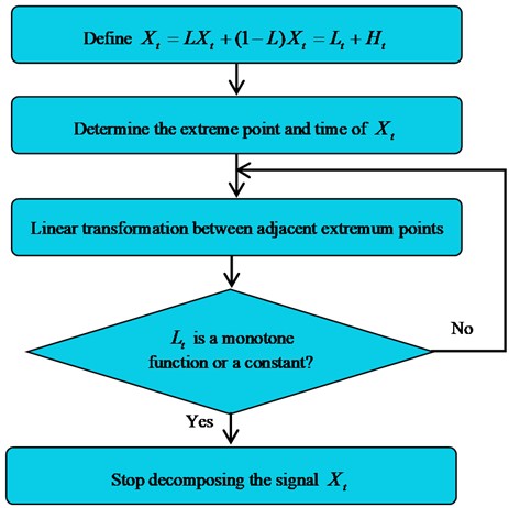
1) Vibration signal is represented as:
2) Figure out , all the extreme points of and related time , in which ( 1, 2,…, ), represents the number of extreme points. Linear gain parameter is within , with 0.5 as a usual option [19]:
3) Linear transformation is performed between adjacent extreme points, as shown in Eq. (3):
4) Replaces with and repeat the step 1-3 until becomes a monotonic function or constant. Given the number of iterations is , can be represented as Eq. (4) after ITD decomposition:
2.2. SVD algorithm
As for the rotational component signal , 1, 2,…, after ITD decomposition, build a Hankel matrix :
Singular value decomposition of is as follow:
In the Eq. (6), and is orthogonal matrix; , transposed matrix of ; , diagonal matrix composed by singular value. Singular value bears the following relation: (in which means being much greater than). represents the th singular value obtained by decomposition, 1, 2,…, . is the order of matrix .
As the singular value of each subsequent term after the term is significantly smaller than previous singular values [23], the singular values of term can be regarded as the singular value to noise component [24]. That means the key to denoising of singular value lies in the option of k, the number of reconstructed terms. As in the Hankel matrix, the vectors of one row lag behind the previous row with only one data point, a sick nature can be observed in the Hankel matrix without noise signal due to the correlation of adjacent rows: the previous singular values are larger and present obvious mutation in some point, while the singular values after that are close to zero. On the contrary, the singular values with noise signal show no correlation between adjacent rows, namely without obvious mutation, but present a parallel line close to lateral axis. For that, difference spectrum of singular value is introduced to determine mutation point . It describes the variation of sequence. As the value of difference sequence is large, the literature [25] has defined difference spectrum as:
Given: difference spectrum sequence , in which singular values of first terms are the ones corresponding to signal and from to the last term, the singular values correspond to noise. For that, the th element is the maximum peak of difference spectrum sequence. Choose the first singular values to build a new diagonal matrix and rebuild original signal :
2.3. ITD-SVD
In this paper, a study has been made to probe into the characteristic extraction and fault diagnosis of compound faults from rolling bearings in aero-engines. The specific ITD-SVD algorithm is shown in the scheme D in Fig. 2. The scheme A in Fig. 2 refers to rebuilding signal with rotational components obtained from ITD algorithm (directly eliminate residual trend terms); scheme B refers to selection of characteristic signals according to rotational components associated with maximum kurtosis; scheme D refers to ITD-SVD algorithm proposed in this paper.
Fig. 2Method flow diagram
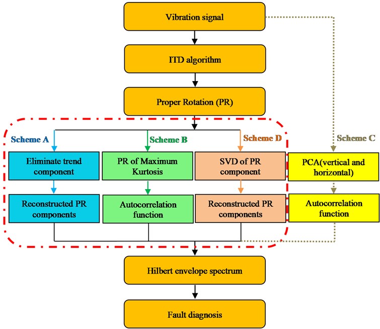
ITD is combined with SVD to extract the characteristics of compound faults in rolling bearings and specific process is shown as follow:
Step 1: vibration signal is decomposed into several PR components and residual trend components based on ITD algorithm;
Step 2: each rotational component is denoised based on singular value difference spectrum algorithm;
Step 3: vibration signal is reconstructed with rotational components denoised;
Step 4: reconstructed signal is subjected to envelope analysis based on Hilbert envelope spectrum; characteristics of compound faults are extracted and fault identification is studied.
3. Characteristic frequency of rolling bearings
As each fault type of rolling bearings is relative to its characteristic frequency [26], it is feasible to identify the type of fault according to characteristic frequency of bearings. Eqs. (10-14) are relevant to the rotational frequency of device and characteristic frequency of inner and outer ring, rolling element and holder of rolling bearing respectively:
where represents rotational speed; for rotational frequency; , and for the characteristic frequency of inner ring, outer ring, rolling element and holder; for the number of rolling elements; for diameter of bearings; for pitch diameter; for the angle between stress direction of rolling elements and vertical line of rollaway of inner and outer rings.
4. Characteristic extraction of compound faults in rolling bearings
All experimental data included in this paper is obtained from rotor-rolling bearing experimental rig, as shown in Fig. 3. The rig is composed by adjustable motor, spin axis, rotor plate, ball bearing, bearing seat and integrated electronic control system. Fig. 4 is the diagram of compound fault of bearings, in which Fig. 4 are relative to compound faults of inner and outer rings, outer ring and rolling elements, inner and outer rings and rolling elements. Bearing damage was made by wire cutting of electric discharge as a simulation in the test and the cutting depth is 0.2 mm. The specific geometrical parameters of rolling bearings are shown in Table 1, in which represents for the number of rolling elements; for bearing diameter; for pitch diameter; for the angle between stress direction of rolling elements and vertical line of rollaway of inner and outer rings.
Table 1Rolling bearing geometrical parameters
7 | 9.6 | 36 | 0 |
Acceleration sensors were fixed to 3 different positions around bearing seat (including horizontal and vertical positions, as shown in Fig. 3 with an aim to compare the sensibility of ITD-SVD algorithm to the installation direction and position of sensors. Firstly, when compound faults occurred in outer and inner ring and rolling elements of rolling bearings, we randomly took the vibration acceleration signal collected by sensors in vertical direction as a case for analysis. Rotational speed is 1869 r/min and rotational frequency 31 Hz. According to Eqs. (10-14), characteristic frequencies of rolling bearings are shown in Table 2.
Fig. 3Aero-engine rotor-rolling bearing experimental rig
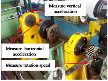
Fig. 4Compound faults of rolling bearing

Table 2Fault characteristic frequency-rotational speed 1869 r/min
Feature frequency | |||||
Fault types | (Hz) | (Hz) | (Hz) | (Hz) | (Hz) |
Outer ring, inner ring and rolling element compound faults | 31 | 11.4 | 138.1 | 79.9 | 54.2 |
4.1. Scheme A: (shown in Fig. 2, marked by blue)
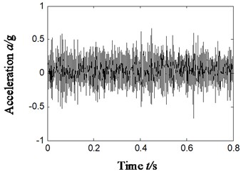
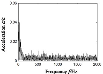
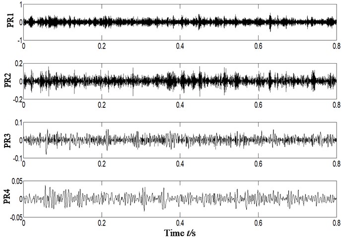
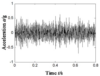
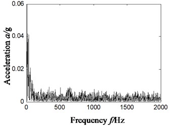
According to scheme A, vibration signal is broken up by ITD algorithm, with residual trend components eliminated and then signal is reconstructed based on the obtained PR components. Extract characteristics of compound faults based on reconstructed signal and make fault diagnosis, and the result is shown in Fig. 5. Fig. 5(a) is the time domain waveform of original signal and Fig. 5(b) is Hilbert envelope spectrum; Fig. 5(c) is the time-domain waveform of rotational components after ITD decomposition; Fig. 5(d) and (e) is the time-domain waveform of reconstructed rotational components and Hilbert envelope spectrum.
It can be found from the analysis of Fig. 5(d)-(e) that no matter the direct envelope analysis of vibration signal or ITD-based algorithm, it is impossible to effectively extract characteristic frequency of rolling bearings according to Hilbert envelope spectrum of reconstructed rotational components (without residual trend components), which means it cannot effectively determine the type of faults.
4.2. Scheme B (shown in Fig. 2, marked by green)
Vibration data of Section 4.1 was reused to facilitate comparative analysis. According to scheme B, kurtosis of each rotational component (obtained by ITD decomposition) was calculated and the one with maximum kurtosis was regarded as optimal rotational component, based on which characteristics of compound faults were extracted. The kurtosis of each rotational component is shown in Table 3.
Fig. 5Compound faults feature extraction of rolling bearing – scheme A
a)
b)
c)
d)
e)
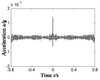
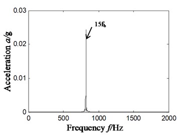
It can be found from Table 3 that PR2 is chosen as optimal rotational component according to the principle of maximum kurtosis. To reduce the influence of noise in signal, we took the self-correlation function of PR2 and extracted the characteristics of compound faults of rolling bearings with the Hilbert envelope spectrum of self-correlation function. The result is shown in Fig. 6. Fig 6(a) and (b) is the self-correlation function of PR2 rotational component and Hilbert envelope spectrum.
Table 3Kurtosis coefficient
PR components | ||||
Index | PR1 | PR2 | PR3 | PR4 |
Kurtosis | 2.9061 | 3.6492 | 3.4704 | 3.4116 |
Fig. 6Compound faults feature extraction of rolling bearing – scheme B
a)
b)
As shown in Fig. 6(b), ITD algorithm is combined with kurtosis and a distinct 820 Hz frequency component can be observed in the Hilbert envelope spectrum of optimal rotational component associated with maximum kurtosis. This frequency component is consistent with the 15-time frequency (820/15 = 54.7 Hz) of characteristic frequency (54.2 Hz) of rolling elements in rolling bearings. It can be observed from scheme B that faults occurred in rolling elements, but this scheme cannot effectively extract the characteristic frequency of inner and outer rings, which means the combination of ITD algorithm and kurtosis unable to make effective judgment of compound faults of rolling bearings.
4.3. Scheme C (shown in Fig. 2, marked by yellow)
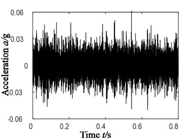
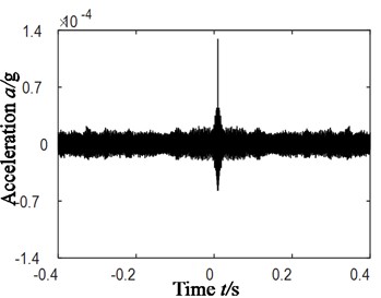
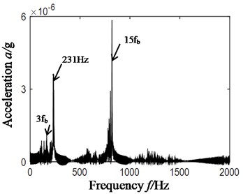
Vibration data of Section 4.1 was used (compound faults occurred in outer and inner ring and rolling elements) to facilitate comparative analysis. The PCA method is used to realize data fusion (the two channels vibration data in the horizontal and vertical direction is selected). To reduced noise, the autocorrelation function is selected. The results obtained by Hilbert envelope spectrum analysis are shown in the Fig. 7. Among them, Fig. 7(a) is the time domain signal after PCA, Fig. 7(b) is the autocorrelation function of Fig.7(a), and Fig. 7(c) is the Hilbert envelope spectrum of Fig. 7(b).
By analyzing Fig. 7(c), it can be concluded that: in Hilbert envelope spectrum can only find 3 times frequency (166 Hz) and 15 times frequency (820 Hz) of rolling element fault characteristic frequency (54.2 Hz) by using PCA method, while the inner ring and outer ring feature frequency cannot be find. In other words, scheme C (PCA) cannot accurately identify compound fault diagnosis types of rolling bearings.
5. Characteristic extraction of compound faults based on ITD-SVD
To address the difficulty in extracting compound faults of rolling bearings, it is crucial to effectively reduce the noise component in signal. SVD can filter out noise component while reserving the impulse nature of signal to the most extent. For that, the combination of ITD and SVD algorithms can serve the characteristic extraction of compound faults in rolling bearings. Firstly, original vibration signal is decomposed by ITD algorithm into proper rotation components which are denoised with difference spectrum of singular value; secondly, vibration signal is reconstructed from denoised proper rotation components; finally, characteristics of compound faults are extracted with Hilbert envelope spectrum of reconstructed signal. Specific process of ITD-SVD algorithm is shown in scheme D, Fig. 2.
Fig. 7Compound faults feature extraction of rolling bearing – scheme C
a)
b)
c)
5.1. Characteristic extraction of compound faults in rolling bearings
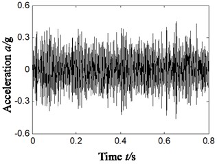
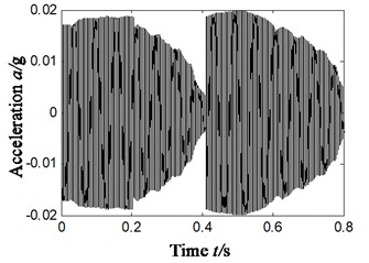
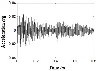
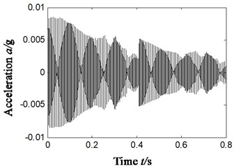
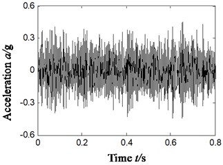
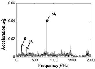
To make a comparative analysis with the scheme A/B/C in Section 4.1-4.3 in terms of the effect of characteristic extraction, the characteristic extraction basic on ITD-SVD algorithm took the same vibration data as Section 4.1. The result is shown in Fig. 8, in which Fig. 8(a1)-(a4) is the denoised rotational component by SVD (obtained by ITD algorithm, as shown in Fig. 5(c)); Fig. 8(a5) is the reconstructed time-domain after denoising (based on Fig. 8(a1) to (a4)); Fig. 8(a6) is the Hilbert envelope spectrum of reconstructed signal.
After analyzing Fig. 8(a6) and comparing it with Fig. 5(e), 6(b) and 7(c) we can find that:
Based on the ITD-SVD (scheme D) algorithm, the frequency components of 138 Hz and 284 Hz, 820 Hz were observed to have larger amplitude in Hilbert envelope spectrum. It can be found from the analysis that these frequencies are relative to the characteristic frequency (138.1 Hz) of inner ring faults, the difference of 4-time frequency of characteristic frequency (79.9 Hz) of outer ring and inversion (31 Hz) ((284+31)/4 = 78.8 Hz), and the 15-time frequency (820/15 = 54.7 Hz) of characteristic frequency of faults in rolling elements. These frequency characteristics are consistent with the type of compound faults of rolling bearings. That means the proposed ITD-SVD algorithm can effectively extract the characteristics of compound faults of rolling bearings and precisely determine the type of faults.
5.2. Different installation positions of sensors
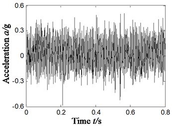
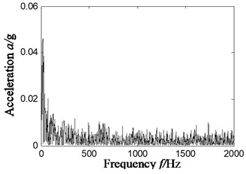
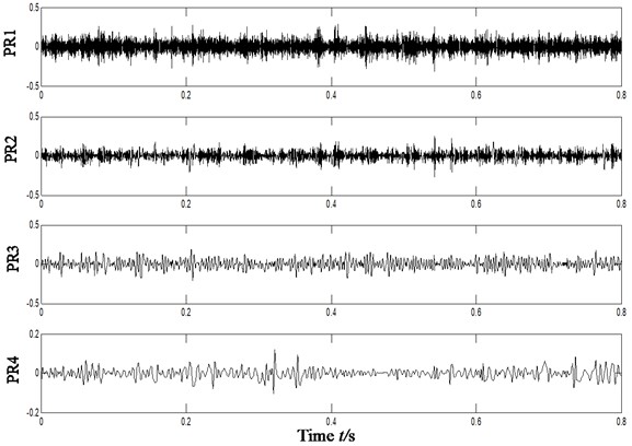
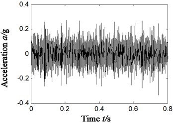
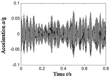
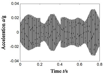
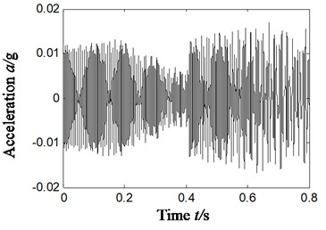
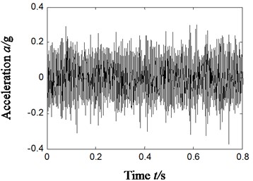
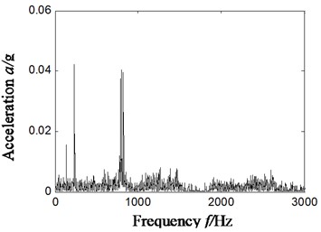
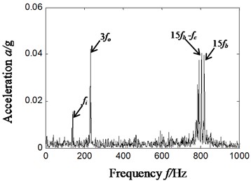
To analyze the sensibility of ITD-SVD algorithm to installation direction and position of sensors, we have chosen the vibration acceleration signal collected by the sensors of horizontal direction in section 4.1 (sensors in vertical direction). Rotation speed remains 1869 r/min and frequency is 31 Hz. Characteristic frequency of outer ring, inner ring, rolling elements and holder is 79.9 Hz, 138.1 Hz, 54.2 Hz and 11.4 Hz respectively. The result is shown in Fig. 9, in which Fig. 9(a) is the time domain waveform of vibration acceleration signal; Fig. 9(b) is the Hilbert envelope of original signal; Fig. 9(c) is the rotational components of acceleration signal; Fig. 9(d1)-(d4) is the time domain waveform of denoised rotational component by ITD-SVD; Fig. 9(d5) is the reconstructed time-domain after denoising (based on Fig. 9(d1)-(d4)); Fig. 9(d6) is the Hilbert envelope spectrum of reconstructed signal; fig. 9(d7) is the partial zoom view of Hilbert envelope spectrum of reconstructed signal.
Fig. 8Compound faults feature extraction of rolling bearing – scheme D-vertical direction
a1)
a2)
a3)
a4)
a5)
a6)
It can be found from the analysis of Fig. 9(d7) that there is distinct characteristic frequency of inner ring fault 138 Hz, 3-time frequency 232 Hz (232/3 = 77.3 Hz) of characteristic frequency (79.9 Hz) of outer ring fault and 15-time frequency (805/15 = 53.6 Hz) of characteristic frequency (54.2 Hz) of faults in rolling elements. As the characteristic frequency of faults in rolling elements is modulated by rotational frequency of holder, there is the difference between the 15-time frequency of fault characteristic frequency of rolling elements and rotational frequency of holder, 794 Hz (805-11.4 = 793.6 Hz).
It can be concluded from the comparison of Fig. 7 and Fig. 8 that with ITD-SVD algorithm, we can effectively extract the characteristic frequency of compound faults of rolling bearings no matter sensors are installed in horizontal or vertical direction, and thereby identify the fault type. That means ITD-SVD algorithm is insensitive to installation direction of sensor.
Fig. 9Compound faults feature extraction of rolling bearing – scheme D-Horizontal direction
a)
b)
c)
d1)
d2)
d3)
d4)
d5)
d6)
d7)
5.3. Other compound faults
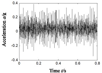
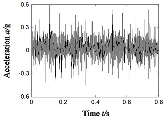
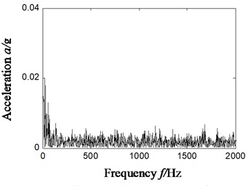
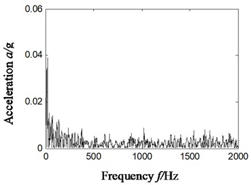
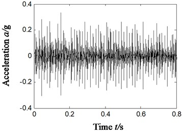
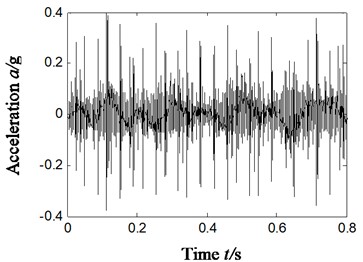
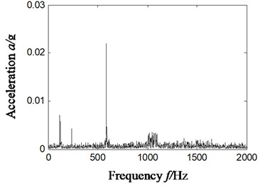
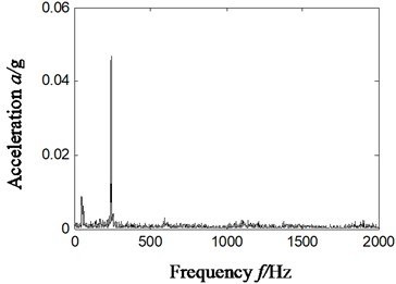
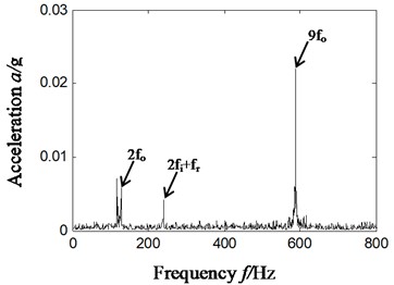
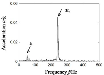
To further validate the effectiveness of ITD-SVD algorithm, we will study the characteristic extraction of other compound faults in rolling bearings based on ITD-SVD next. Compound faults of outer and inner rings (sensors were fixed vertically), outer ring and rolling elements (sensors were fixed horizontally) were randomly chosen for the study based on ITD-SVD algorithm and the result is shown in Fig. 10. Fig. 10(a1)-(b1) shows the time domain waveform of vibration signal; Fig. 10(a2)-(b2), the Hilbert envelope spectrum of original vibration signal; Fig. 10(a3)-(b3), time domain waveform of reconstructed signal with ITD-SVD; Fig. 10(a4)-(b4), Hilbert envelope spectrum of reconstructed signal; Fig. 10(a5)-(b5), partial zoom of Hilbert envelope spectrum of reconstructed signal; Fig. 10(a1)-(b5), compound faults of outer and rolling elements.
Figure out the characteristic frequencies of different compound faults according to Eqs. (10-14). The result is shown in Table 4.
From the analysis of Fig. 10(a5), we can find some distinct frequency components, like 129 Hz, 589 Hz and 24 Hz in the Hilbert envelope spectrum based on ITD-SVD algorithm. These frequency components are relative to 2-time and 9-time frequency (589/9 = 65.4 Hz) of outer-ring characteristic frequency 65 Hz, the sum of 2-time frequency of inner-ring characteristic frequency 112 Hz and inversion 25 ((241-25)/2 = 108 Hz), which is consistent with the state of compound faults of inner and outer rings.
Fig. 10Compound faults feature extraction of rolling bearing – scheme D: outer ring and inner ring compound fault (a1-a5); outer ring and rolling element compound fault (b1-b5)
a1)
b1)
a2)
b2)
a3)
b3)
a4)
b4)
a5)
b5)
From the analysis of Fig. 10(b5), we can find some distinct frequency components, like 53 Hz and 240 Hz in the Hilbert envelope spectrum based on ITD-SVD algorithm. It can be found from the analysis that these frequency components are relative to the 3-time frequency (240/3 = 80 Hz) of fault characteristic frequency (52.6 Hz) of rolling elements and that (77.5 Hz) of outer-ring. The result is consistent with the state of compound faults of rolling elements and outer ring.
Table 4Fault characteristic frequency and related parameters
Fault types | Sensor position | (r/min) | (Hz) | (Hz) | (Hz) | (Hz) | (Hz) |
Outer ring and inner ring fault | Vertical | 1515 | 25 | 9.3 | 112 | 65 | 44 |
Outer ring and rolling element fault | Horizontal | 1813 | 30 | 11 | 134 | 77.5 | 52.6 |
That is to say the proposed ITD-SVD algorithm can precisely and effectively extract characteristic frequencies of different compound faults in rolling bearings and thereby determine the type of faults.
6. Conclusions
ITD algorithm is combined with difference spectrum of SVD to extract characteristic frequencies of compound faults in rolling bearings and then determine the type of faults. The result indicates that:
1) With ITD-SVD algorithm, no matter sensors are installed horizontally or vertically, we can still effectively the characteristic frequencies of compound faults in rolling bearings and precisely determine the fault type.
2) Meanwhile, the algorithm can make precise diagnosis on characteristics of different compound faults, which means the algorithm is insensitive to the type of compound faults. However, traditional ITD algorithm (combination of reconstructed rotation components, ITD and kurtosis) and PCA combined with autocorrelation are unable to make effective extraction of characteristic frequency of compound faults in rolling bearings.
3) As computation is rather slow due to a large dimension of Hankel matrix, it is more suitable for off-line data analysis and treatment.
References
-
Zhang Wan Study on Weak Fault Feature Extraction of Rolling Element Bearing Based on Signal Sparse Representation. Southeast University, 2018.
-
Chen Yongqi, et al. Fault diagnosis of roller bearing based on intrinsic time-scale decomposition. Journal of Electronic Measurement and Instrumentation, Vol. 29, Issue 11, 2015, p. 1677-1682.
-
Deng Xiaowen, Yang Ping, et al. Rolling bearings time and frequency domain fault diagnosis method based on Kurtosis analysis. 6th IEEE PES Asia-Pacific Power and Energy Engineering Conference, 2014.
-
Zhang Yu, Jiang Wen, Deng Xinyang Fault diagnosis method based on time domain weighted data aggregation and information fusion. International Journal of Distributed Sensor Networks, Vol. 15, Issue 9, 2019, https://doi.org/10.1177/1550147719875629.
-
Chen Fei, Huang Lai, et al. Fault diagnosis method of information exergy based on space-time feature spectrum in frequency domain. Journal of Vibration, Measurement and Diagnosis, Vol. 34, Issue 5, 2014, p. 898-904.
-
Jiang Wanlu, Zhu Yong, et al. Fault diagnosis method based on precise frequency domain integral and vibration severity. ICIC Express Letters, Part B: Applications, Vol. 7, Issue 11, 2016, p. 2301-2307.
-
Chen Renxiang, Tang Baoping, Ma Jinghua Adaptive de-noising method based on ensemble empirical mode decomposition for vibration signal. Journal of Vibration and Shock, Vol. 31, Issue 15, 2012, p. 82-86.
-
Kankar P. K., et al. Rolling element bearing fault diagnosis using autocorrelation and continuous wavelet transform. JVC/Journal of Vibration and Control, Vol. 17, Issue 14, 2011, p. 2081-2097.
-
Tang Xianguang, Guo Yu, et al. Application of rolling element bearing envelope analysis based on short time Fourier transition and independent components analysis. Journal of Mechanical Strength, Vol. 34, Issue 1, 2012, p. 1-5.
-
Liu Hongmei, Wang Xuan, Lu Chen Rolling bearing fault diagnosis under variable conditions using hilbert-huang transform and singular value decomposition. Mathematical Problems in Engineering, Vol. 2014, 2014, p. 765621.
-
Wang Luyan, Wang Qiang, et al. An improved extension method of EMD based on SVRM. Applied Mechanics and Materials, Vol. 543, Issue 547, 2014, p. 2697-2701.
-
Wang Guobiao, He Zhengjia, et al. Basic research on machinery fault diagnosis-what is the prescription. Journal of Mechanical Engineering, Vol. 49, Issue 1, 2013, p. 63-72.
-
Tang Guiji, Deng Feiyue, et al. Compound fault features separation method of rolling element bearing based on improved harmonic wavelet packet decomposition. Chinese Journal of Scientific Instrument, Vol. 36, Issues 1, 2015, p. 143-151.
-
Hu Aijun, Zhao Jun, et al. A compound fault feature separation method of rolling bearing based on correlation kurtosis resonance demodulation. Journal of Vibration and Shock, Vol. 38, Issues 8, 2019, p. 110-116.
-
Mark G. F., Ivan O. Intrinsic time scale decomposition: time-frequency-energy analysis and real-time filtering of non-stationary signals. Proceedings of the Royal Society A, Vol. 463, 2007, p. 321-342.
-
Zhang L., Li P., Li M., et al. Fault diagnosis of rolling bearing based on ITD fuzzy entropy and GG clustering. Chinese Journal of Scientific Instrument, Vol. 35, Issue 11, 2014, p. 2624-2632.
-
Guan Jiaoyue, Tian Jing, Zhao Jingming, et al. Fault feature extraction method of rolling bearing based on intrinsic time-scale decomposition and multiscale morphological filtering. Science Technology and Engineering, Vol. 19, Issue 14, 2019, p. 178-182.
-
Yu Jianbo, Lyu Jingxiang, et al. Fault diagnosis for rolling bearing based on ITD and improved morphological filter. Journal of Beijing University of Aeronautics and Astronautics, Vol. 44, Issue 2, 2018, p. 241-249.
-
Zhang Ying, Zhang Chao, et al. Fault diagnosis method for bearing based on improved intrinsic time-scale decomposition and spectrum kurtosis. Acta Energiae Solaris Sinica, Vol. 38, Issue 3, 2017, p. 699-706.
-
Sun Hongchun, Guo Jingzheng, et al. Improved singular value decomposition (Top SVD) for source number estimation of low SNR in blind source separation. IEEE Access, Vol. 5, 2017, p. 26460-26465.
-
Cheng Zhi, He Feng, Jing Xu, et al. Denoising lidar signal based on ensemble empirical mode decomposition and singular value decomposition. Acta Photonica Sinica, Vol. 46, Issue 12, 2017, p. 1201003.
-
Cui Weicheng, Li Wei, et al. Bearing fault diagnosis based on singular value decomposition denoising and local characteristic-scale decomposition. Journal of Mechanical Transmission, Vol. 40, Issue 5, 2016, p. 128-133.
-
Liu Shudan, Chen Zhixing Nonlinear vibration signal de-noising based on singular value decomposition and EEMD. Journal of Detection and Control, Vol. 41, Issue 3, 2019, p. 37-42.
-
Zhang Bo, Li Jianjun Denoising method based on Hankel matrix and SVD and its application in flight flutter testing data preprocessing. Journal of Vibration and Shock, Vol. 28, Issue 2, 2009, p. 162-166+208.
-
Zhao Xuezhi, Ye Bangyan, et al. Selection of effective singular values based on curvature spectrum of singular values. Mechanical Systems and Signal Processing, Vol. 25, Issue 5, 2011, p. 1617-1631.
-
Wang Wei, Li Jun, et al. Research on the Early weak fault diagnosis of aero-engine inter shaft bearing. Machinery and Electronics, Vol. 37, Issue 6, 2019, p. 6-10.
Cited by
About this article
This work was supported by National Natural Science Foundation of China (Grant No. 51605309), Natural Science Foundation of Liaoning Province (Grant No. 2019-ZD-0219), Aeronautical Science Foundation of China (Grant No. 201933054002) and Provincial Education Department of Liaoning Province (Grant No. JYT19042).
