Abstract
Headlamps mounted on vehicles are one of the major components which contribute to the driver’s vision and thus, they should be robustly designed to prevent looseness of the supporting bolts from the vibration generated while driving. For that reason, it is important to select proper position of the headlamp supporting positions initially. However, no criteria for positioning the headlamp bolts are specified now and the bolts are placed according to the design of the whole vehicle without any interference with other parts. This may cause excessive vibration on the module and the bolts could be loosened, causing the change of aiming and adjustment. Therefore, as a first step for establishing the headlamp positioning criteria, this study aims to predict the force transmitted to the bolts when excitation forces are given to the headlamp. The following three steps are conducted for this purpose: 1) a typical headlamp module is modeled based on the lumped parameter modeling and the equation of motions are derived, 2) the force transmitted to the bolts in each direction are calculated, 3) the appropriate parameter adjustment is performed comparing transmitted force with one obtained through finite element analysis and experimental results. It is shown that the directional force transmitted to the headlamp bolt could be predicted when the excitation force was applied.

Highlights
- In this study aims to predict the force transmitted to the bolts when excitation forces are given to the headlamp.
- A typical headlamp module is modeled based on the lumped parameter modeling and the equation of motions are derived.
- The force transmitted to the bolts in each direction are calculated based on the base excitation theory and the Runge-Kutta method.
- In order to validate the theoretical values, it was compared to experiment results.
- Through compared each results, the directional force transmitted to the headlamp bolt could be predicted through theoretical method.
1. Introduction
The headlamp is a part that contributes to the driver's vision and is directly related to safety issues in case of failure. Thus, it should be robustly designed to withstand vibration loads generated during driving even for normal operation. Proper headlamp bolt positioning plays an important role for robust design, while the exact criteria for the location of the headlamp bolts are not suggested yet. Those positions have been arbitrarily assigned within the range that does not cause interference with other components during initial design step and then the bolt can be loosened and aiming / adjustment of the module is arbitrarily modified due to excessive vibration generated while driving.
Many researches have been devoted to the design of headlamps as follows. Sökmen et al. [1] conducted a headlamp cooling solution using LEDs and conducted experiments with different materials, demonstrating a positive effect on temperature when copper was used. Lin et al. [2] studied the chimney geometry and showed that it was reduced by 3.8 to 4.6 ℃ by applying it to the headlamp. Singh et al. [3, 4] proposed a design using a heat pipe as a cooling solution for LED headlamps, which is 40-50 % lighter than the conventional method. In addition, it showed 2-3 times higher heat removal capacity. Yeh et al. [5] proposed a design using a reflector in the lamp module and showed that the proposed method satisfies the type of light presented in the ECE R 123 regulations. Tsal et al. [6] proposed a design using an optimized cylindrical lens array. Through this design, color contrast was increased by suppressing linearity of cutoff lines and roughness of dark areas. Yip et al. [7] integrates Taguchi method and Principal Component Analysis (PCA) for lens shape optimization and shows that the proposed method improves LED light source by more than 92 %. Ma et al. [8, 9] proposed an achromatic LED projection headlamp to correct color diffusion, a phenomenon seen in cut-off lines. The proposed method shows that the color dispersion of the cut-off line is reduced. Kharche et al. [10] conducted a vibration analysis on the MCM300 headlamps to identify natural frequencies and amplitudes, and confirmed that the numerical values appeared above 35 Hz, which satisfies customer requirements. Above studies are mainly focused on thermal analysis, optics, and lens optimization, while the study on vibration analysis has been done for only limited models.
This study is focused on the calculation of transmitted force applied to headlamp supporting points, which can be utilized in the procedure of selecting the best position of headlamp bolts. This article covers the followings: 1) Equation of motions for the headlamp module are derived with lumped parameter modeling. 2) The transmitted force of each bolt is calculated using the Runge-Kutta method based on the equation of motions. 3) Related parameters are estimated by comparing theoretical and numerical results.
2. Mathematical modeling for headlamp
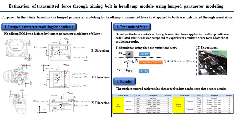
Mathematical modeling is performed based on lumped parameter model in the , , and directions, where there are three degrees of freedom in each direction. The free body diagram for each direction is shown in Fig. 1. In Fig. 1, and represent the mass corresponding to the projection unit and housing, respectively. , , and represent the moment of inertia for each direction, repectively. is corresponding to distance from the center of mass, where are in the direction, are in the direction, and are in the direction. Also, and represent the stiffness and damping coefficient for the pivot bolt and and represent the stiffness and damping coefficient for aiming bolts.
and represent the displacement correponding to the housing and projection unit, respectively. are corresponding to each directional force. The mass, distance of center of mass and, stiffness were measured and calculated using the FEM analysis. Based on the FBD of Fig. 1, the equation of motion can be summarized as shown in Eqs. (1) to (9):
Fig. 1Free body diagram

a)

b)

c)
3. Prediction of bolt loosening
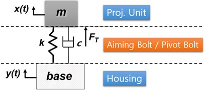
In order to calculate the transmitted force applied headlamp bolts, base excitation theory is used. In Fig. 2(a), the base excitation theory is explained with the headlamp model during driving. When the headlamp is excited by the vibration generated while driving, the housing part becomes the base part and transmits the excitation force to the projection unit through the bolt. Therefore, the transmitted force can be calculated using Eq. (10):
Based on the equation of motion in Section 2, transmitted forces are calculated using Runge-Kutta method.
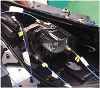
In order to match the realistic value with these analytical results, finite element analysis has been done at first. Transmitted forces are numerically calculated with the same excitation force and those results are utilized for adjusting parameters of the equations of motion. Secondly, this model is again adjusted with experimental results. Since the transmitted force cannot be directly measured through experiments, bolt looseness is checked and it is compared with the analytical results. This study predicts transmitted forces and bolt looseness can be determined by the work from Park et al. [11]. The experiment is performed by adding sinusoidal excitation to the brackets of the four different modules, attached accelerometers as shown in Fig. 2(b). For varying the experimental conditions, additional masses are attached to the module which can move the center of mass. Table 1 shows whether the bolt looseness matches with the analytical results or not.
Fig. 2a) Base excitation concept, b) experiment setup

a)

b)
Table 1Comparison of theoretical and experimental results
Vehicle model | Case | Description | Matches | |
Kia Stinger | Version 1 | Base | Original | O |
Case 1 | Original + 260 g mass | Ⅹ | ||
Case 2 | Original + 160 g mass | O | ||
Case 3 | Original + 140 g mass | Ⅹ | ||
Version 2 | Base | Original | O | |
Case 1 | Original +260 g mass | Ⅹ | ||
Case 2 | Original +160 g mass | O | ||
Case 3 | Original + 140 g mass | Ⅹ | ||
Hyundai Sonata | Version 1 | Base | Original | O |
Case 1 | Original + 330 g mass | O | ||
Case 2 | Original + 190 g mass | O | ||
Case 3 | Original + 300 g mass | O | ||
Version 2 | Base | Original | O | |
Case 1 | Original + 330 g mass | O | ||
Case 2 | Original + 190 g mass | O | ||
Case 3 | Original + 300 g mass | O | ||
The results show that the results from 12 cases among total 16 cases are matched, while remaining 4 cases are not matched. Except for above four cases, the results can be seen that proper results are obtained between theory and experiment through parameter adjustment.
4. Conclusions
This article covers the followings to calculate the transmitted force applied to the headlamp supporting positions: 1) Equation of motions for the headlamp module are derived with lumped parameter modeling. 2) The transmitted force of each bolt is calculated using the Runge-Kutta method based on the equation of motions. 3) Related parameters are estimated by comparing theoretical and numerical results. Through the following process, it was shown that the transmitted force applied to headlamp bolt can be calculated and be applied to the process determining the looseness of aiming bolts. Future research can cover the determination of the stiffness of the headlamp module by estimating natural frequencies with changing supporting locations. With this, the positioning criteria can be obtained along with the transmitted forces.
References
-
Sökmen K. F., Yürüklü E., Yamankaradeniz N. Computational thermal analysis of cylindrical fin design parameters and a new methodology for defining fin structure in LED auto-mobile headlamp cooling applications. Applied Thermal Engineering, Vol. 94, 2016, p. 534-542.
-
Lin S., Chen Y., Wu Y., YenH. Chimney-enhanced design applied on the thermal management of LED vehicle headlamp. Transactions of the Canadian Society for Mechanical Engineering, Vol. 40, Issue 4, 2016, p. 521-532.
-
Park T. H., Ji H. S., Kim S. Y., Kim O. W., Kim K. S. Heat radiation effect of passenger car headlamp using plate heat pipe. Defect and Diffusion Forum, Vol. 390, 2019, p. 112-124.
-
Singh R., Mochizuki M., Yamada T., Nguyen T. Cooling of LED headlamp in automotive by heat pipes. Applied Thermal Engineering, Vol. 116, 2020, p. 114733.
-
Tsai M., Sun C., Yang T., Wu C., Lin S., Lee X. Robust optical design for high-contrast cutoff line in vehicle forward lighting. OSA Continuum, Vol. 2, Issue 4, 2019, p. 1080-1088.
-
Yeh C., Han P. Wang I., LinE. Using design of experiment for parameter optimization on smart headlamp optics design. Applied Optics, Vol. 58, Issue 28, 2019, p. 7661-7683.
-
Yip W., To S., WangW. Design of an optical lens for LED lighting using a hybrid principal components analysis-Taguchi method. Lighting Research and Technology, Vol. 51, Issue 5, 2018, p. 788-802.
-
Ma S., Lee C., YangC. Achromatic LED-based projection lens design for automobile headlamp. Optic-International Journal for Light and Electron Optics, Vol. 191, 2019, p. 89-99.
-
Lee H. S., Park H. J., Kwak J. S. Improvement of disturbing color effects depending on the axial color of an automotive headlamp lens. Applied Optics, Vol. 56, Issue 17, 2017, p. 5106-5111.
-
Kharche S., Karajagi P., KulkarniR. Design development and vibration analysis of MCM300 headlamp. International Journal of Engineering Trends and Technology (IJETT), Vol. 38, Issue 3, 2016, p. 168-175.
-
Moon J. S., Baek H., Park S. S., Park J. M. Analysis of self loosening of aiming bolts in vehicle head lamp. Journal of the Korean Society of Tribologists and Lubrication Engineers, Vol. 35, Issue 1, 2019, p. 65-70.
About this article
This study was supported by the SL Corporation and the National Research Foundation of Korea (NRF) grant funded by the government of Korea (Ministry of Science, ICT & Future Planning) (No. 2019R1F1A1061172).
