Abstract
The aim of this study is to investigate free vibration characteristics of arch-frames which consist of two columns and an arch. Firstly, an exact formulation of the problem is presented using the Dynamic Stiffness Method (DSM). The end forces and displacements of column elements are obtained analytically using Timoshenko beam theory (TBT). These are then combined with the end forces and displacements of the semi-circular arch, which is modeled with exact curved beam elements that consider axial and shear deformations and rotational inertia. By employing standard assembly and bisection based root finding procedures, exact free vibration analysis of the whole vibrating system is carried out. Then, in an effort to simplify the formulations, an approach based on approximating the arch as assembly of linear straight beam segments is presented. The calculated natural frequencies using DSM for both exact and approximate results are then tabulated for comparison purposes. The mode shapes are also compared. The results show that the proposed model simplification is effective and produces accurate mode frequency and shape estimations.
1. Introduction
The dynamic behaviour of arch-frames is of direct relevance for structural bridge engineering applications. Natural vibration frequencies and mode shapes of these structures govern their response to dynamic excitations (due to moving traffic loads, wind and earthquakes). In the literature, studies concerning vibrations of curved beams are limited when compared to literature on dynamic behaviour of straight beams. The simplest curved beam formulations [1-3] ignore shear deformations, rotational inertia and axial extensibility of the curved beam. However, these assumptions result in an overestimation of natural frequencies. A limited number of analytical studies consider the aforementioned aspects [4-7]. More specifically, these studies carry out free vibration analysis of circular beams having various boundary conditions using the DSM [4, 6, 8, 9].
This study derives exact and simplified DSM formulation of a single-span semi-circular arch-frame in Section 2. This is achieved by modeling columns as Timoshenko beams and modeling the arch as a curved beam considering axial and shear deformations and rotational inertia. To simplify this complex formulation, an approximate approach is then proposed, where the arch is modelled with equal length straight Timoshenko beam segments. The adequacy of this simplified model is then evaluated by comparing mode frequencies and shapes from this model to the exact model in Sections 2 and 3. The results are evaluated in Section 4. The main novelty of this study is based on combining the dynamic stiffness approach and segmentation of the arch into straight Timoshenko beam segments for free vibration analysis of arch-frames.
2. Model and formulations
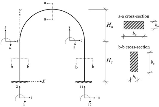
The arch-frame having 4 joints where each joint has horizontal displacement, vertical displacement and rotation presented in Fig. 1 is considered where is the span length, and are global coordinate axes, and are height of the arch and height of the columns, respectively, and are the rectangular cross-sectional dimensions of the arch, and are the rectangular cross-sectional dimensions of the columns. The following assumptions are made: i) The behaviour of frame members is linear elastic, ii) the material of frame members is isotropic, iii) the cross-sections of frame members are uniform, and iv) the effects of damping are neglected.
Fig. 1The arch-frame model consisting of two fixed supported columns and a curved beam

In the following, only the equations of motion of the curved beam are presented. Straight Timoshenko beam formulations used here (which will be used later to describe the columns and arch segments) can be found in the literature [10]. The equation of motion of a curved beam considering axial and shear deformation and rotational inertia is written as follows [6]:
where is cross-sectional area, is modulus of elasticity, is radius of curvature (equal to for the semi-circular arches considered in this study), is shear correction factor (which equals 1.2 for rectangular cross-sections), is shear modulus, is density, is relevant moment of inertia, is radial displacement function, is tangential displacement function, is cross-section rotation due to bending, and are angular coordinate and time, respectively. Eq. (1) can be arranged as:
where , is total angle of embrace of the arch (equal to for a semi-circular arch), and:
The system has a harmonic solution. Therefore, Eq. (2) can be re-arranged by using , and as:
where , and is natural circular frequency. After achieving the solution of coupled Eq. (3) by usual manner, , and can be obtained. The axial force , shear force and bending moment with , and functions are presented in Table 1, where are unknown constants, are characteristic roots obtained from solution of sixth order coupled Eq. (3) and:
Table 1Symbolic definitions of displacement and force functions
3. Application of DSM
The dynamic stiffness matrix of the arch is constructed by using analytically obtained end forces and displacements. The local end displacement vector of the arch and the coefficient vector can be written as Eqs. (4-5), respectively:
where .
The end force vector of the arch () is given in Eq. (6) as:
where .
The sign convention in Eq. (7) is valid for end force relations:
The relations of and are obtained by using Eqs. (4-7) and Table 1 where and represent coefficient matrices constructed using Eqs. (4) and (6), respectively.
The dynamic stiffness matrix of curved beam is obtained using the relation between and as: , , where represents local dynamic stiffness matrix the curved beam. The global dynamic stiffness matrix of the curved beam is obtained by using the angular transformation matrix. The angular transformation matrix and global dynamic stiffness matrix of the arch are given in Eqs. (8-9), respectively:
where represents the angle between local axes at the ends of arch and global axes of the frame structure.
The same procedure is repeated for straight Timoshenko element frame members. The global dynamic stiffness matrix of the arch-frame structure is constructed by assembling these matrices. The natural frequencies are then obtained by equating the determinant of the global dynamic stiffness matrix of the arch-frame structure to zero. A root finding algorithm (based on an iterative bisection approach) is used for obtaining natural frequencies. The mode shapes can then be calculated and plotted.
4. Numerical analysis and discussions
The following geometric and material properties are considered: 8 m, 4 m, 4 m, embrace angle of the arch = 180°, radius of curvature of the arch = 4 m, unit weight of frame members: 2500 kg/m3, modulus of elasticity of frame members: 3×10⁷ kN/m2, Poisson’s ratio of frame members = 0.3, 1.00 m, 0.50 m, 1.00 m.
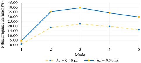
In the first part of numerical case study, the free vibration analysis of the arch-frame model is performed using exact curved beam formulations. The first five exact natural frequencies of the arch-frame are presented in Table 2 for various arch cross-sections. According to Table 2, an augmentation of arch thickness increases all natural frequencies. Fig. 2 which is plotted using the data in Table 2, represents the natural frequency increment by taking 0.40 m and 0.50 m, respectively. It can be observed that the first vibration mode frequency, which is dominated by column sway, is not affected significantly by changes in arch cross-section. However, as shown in Fig. 2, thicker arches have increased natural frequencies (up to 40 %) for 2nd to 5th modes.
The same arch is also described with a simpler model, where it is divided into equal length straight Timoshenko beams. Three different segmentations are considered. The lengths of straight beam segments are 2.4721 m, 1.2515 m and 0.8362 m for 5, 10, and 15, respectively. It should be noted that the local degrees of freedom of the straight segments need to be rotated to global degrees of freedom during assembly (see Eq. (8)). The values of transformation angles are different for 5, 10, and 15 but these values are not presented to improve the clarity of paper. The first five natural frequencies of the arch-frame using the segmented curved beam approach can be observed from Table 3 for 0.30 m, 0.40 m and 0.50 m. Table 3 shows that proposed approach converges fast. The relative errors between exactly calculated natural frequencies and the results those obtained from 15 segmented arch model are presented in Table 4.
Table 2First five exact natural frequencies of arch-frame model
Mode | 1st | 2nd | 3rd | 4th | 5th |
0.30 (m) | 35.3824 | 79.5071 | 146.1644 | 229.4268 | 327.6091 |
0.40 (m) | 35.7264 | 94.3525 | 179.1044 | 274.9525 | 380.7456 |
0.50 (m) | 36.9646 | 107.7696 | 204.2849 | 308.1668 | 425.1134 |
Fig. 2Increment of natural frequencies taking ha= 0.40 m and ha= 0.50 m

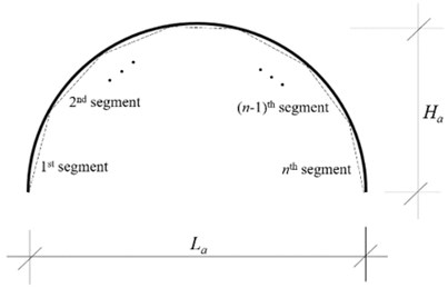
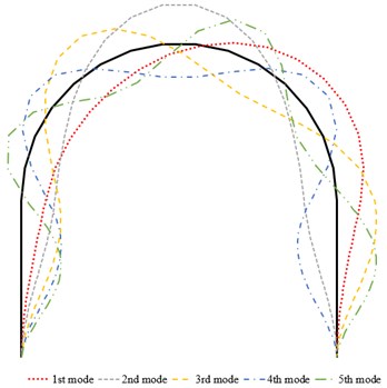
According to Table 4, the maximum relative error of proposed approach taking 15 is 0.65 %. The segmented arch model can also be effectively used to plot mode shapes. The schematic representation of segmented arch where is total segment number and the first five mode shapes of the arch-frame model using 15 are presented in Fig. 3. These are near-identical to exact results (not shown for clarity).
Table 3First five natural frequencies obtained by segmentation approach (rads-1)
(m) | Mode | 1st | 2nd | 3rd | 4th | 5th |
0.3 | 5 | 36.6765 | 83.2312 | 151.4298 | 235.7451 | 335.5829 |
10 | 35.7016 | 80.4054 | 147.4979 | 231.3296 | 330.9019 | |
15 | 35.5258 | 79.9083 | 146.7663 | 230.2983 | 329.1135 | |
Exact | 35.3824 | 79.5071 | 146.1644 | 229.4268 | 327.6091 | |
0.4 | 5 | 37.1930 | 98.5466 | 184.4356 | 282.5921 | 395.9358 |
10 | 36.0844 | 95.3759 | 180.4978 | 277.2384 | 385.2963 | |
15 | 35.8866 | 94.8105 | 179.7369 | 275.9985 | 382.8086 | |
Exact | 35.7264 | 94.3525 | 179.1044 | 274.9525 | 380.7456 | |
0.5 | 5 | 38.5939 | 111.8972 | 209.1147 | 318.0469 | 447.5858 |
10 | 37.3619 | 108.7902 | 205.5938 | 311.0617 | 431.1867 | |
15 | 37.1421 | 108.2281 | 204.8830 | 309.4885 | 427.8523 | |
Exact | 36.9646 | 107.7696 | 204.2849 | 308.1668 | 425.1134 |
Table 4Relative errors between 15 segmented arch model and exact results (%)
(m) | 1st mode | 2nd mode | 3rd mode | 4th mode | 5th mode |
0.30 | 0.41 | 0.50 | 0.41 | 0.38 | 0.46 |
0.40 | 0.55 | 0.60 | 0.42 | 0.45 | 0.65 |
0.50 | 0.48 | 0.43 | 0.29 | 0.43 | 0.64 |
Fig. 3a) Schematic representation of segmented arch where n is total segment number, b) first five mode shapes of arch-frame plotted using 15 segmented arch model (ha= 0.50 m)

a)

b)
5. Conclusions
Exact natural frequencies of an arch-frame structure having straight columns and a curved beam (considering axial and shear deformations and rotary inertia effects) are obtained. Standard DSM approaches are used for this purpose. In order to simplify the formulations, an approximate model based on segmenting the arch into straight Timoshenko beams is then considered. The free vibration analysis of both approximate and exact systems demonstrated that segmenting the arch with linear elastic elements is effective; with only a few straight segments, natural frequency and vibration mode shapes of the curved arch are accurately estimated.
Although the formulations of exact curved beams are complicated, the exact free vibration results can only be obtained using these formulations. Another advantage of using the exact end forces and displacements of the curved beam is the small size of global dynamic stiffness matrix of whole vibrating system. In contrast, while straight beam formulations are simple, segmenting the arch into straight beams increases the size of the global dynamic stiffness matrix of the system. This increases the computation time for the root finding algorithm. While this increase in computation time may be prohibitive for very large and complex systems, this is unlikely to be a problem for determining single and multi-span arch frames encountered in engineering applications.
References
-
Henrych J. The dynamics of arches and Frame. Elsevier, New York, 1981.
-
Irie T., Yamada G., Tanaka K. Natural frequencies of out-of-plane vibration of arcs. Journal of Applied Mechanics, Vol. 49, 1982, p. 910-913.
-
Chidamparam P., Leissa A. W. Vibrations of planar curved beams, rings and arches. Applied Mechanics Reviews, Vol. 46, Issue 9, 1993, p. 467-483.
-
Issa M. S., Wang T. M., Hsiao B. T. Extensional vibrations of continuous circular curved beams with rotary inertia and shear deformation, I: free vibration. Journal of Sound and Vibration, Vol. 114, Issue 2, 1987, p. 297-308.
-
Friedman Z., Kosmatka J. B. An accurate two-node finite element for shear deformable curved beams. International Journal for Numerical Methods in Engineering, Vol. 41, 1998, p. 473-498.
-
Eisenberger M., Efraim E. In-plane vibrations of shear deformable curved beams. International Journal for Numerical Methods in Engineering, Vol. 52, 2001, p. 1221-1234.
-
Lee J. In-plane free vibration analysis of curved Timoshenko beams by the pseudospectral method. KSME International Journal, Vol. 17, Issue 8, 2003, p. 1156-1163.
-
Caliò I., Greco A., D’urso D. Free vibrations of spatial Timoshenko arches. Journal of Sound and Vibration, Vol. 333, 2014, p. 4543-4561.
-
Yang F., Sedaghati R., Esmailzadeh E. Free in-plane vibration of curved beam structures: A tutorial and the state of the art. Journal of Vibration and Control, Vol. 24, Issue 12, 2018, p. 2400-2417.
-
Banerjee J. R., Ananthapuvirajah A. An exact dynamic stiffness matrix for a beam incorporating Rayleigh-Love and Timoshenko theories. International Journal of Mechanical Sciences, Vol. 150, 2019, p. 337-347.
Cited by
About this article
The authors would like to acknowledge the support of the Scientific and Technological Research Council of Turkey (TUBITAK) 2214-A International Doctoral Research Fellowship Programme.
