Abstract
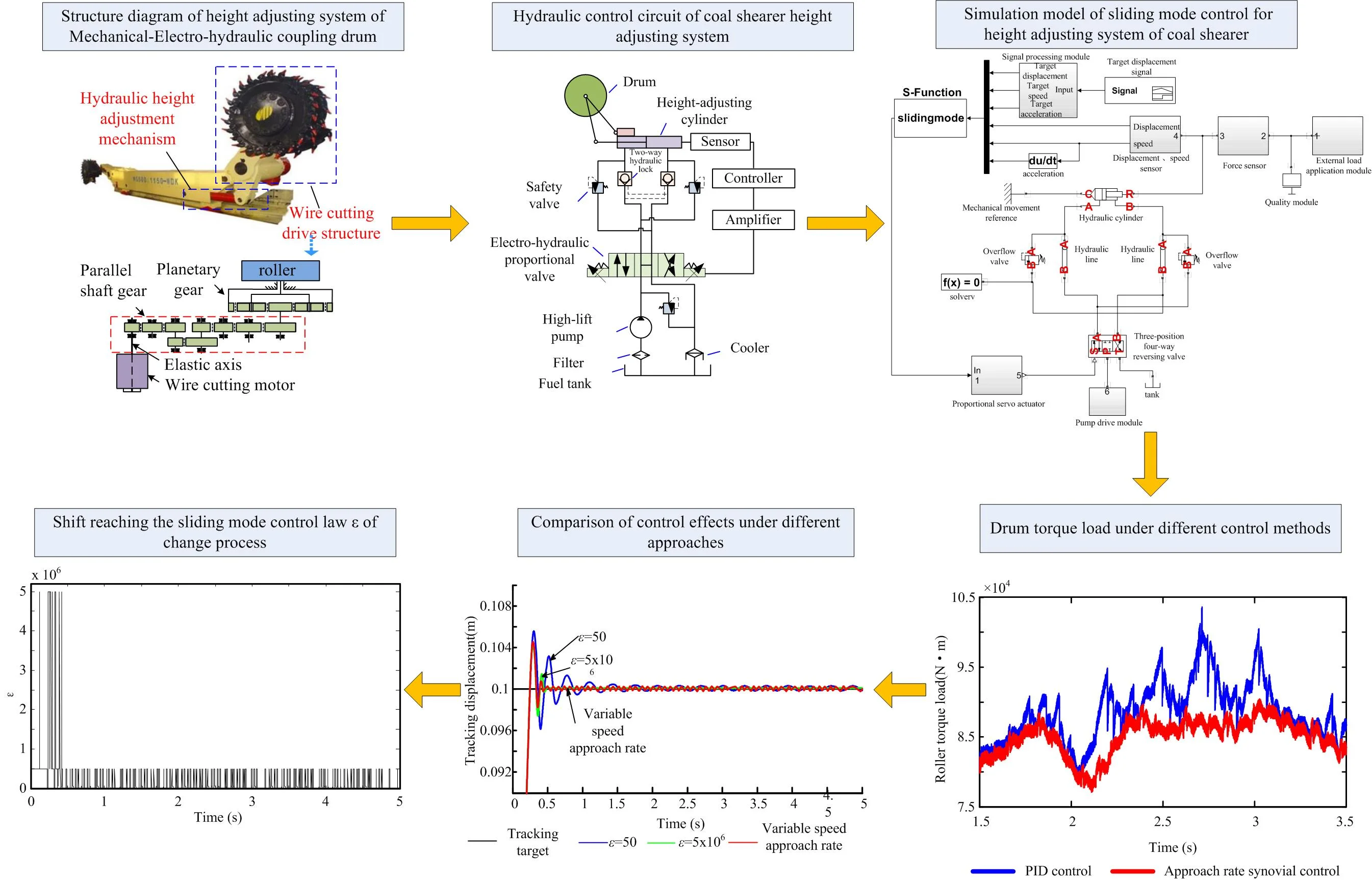
Aiming at the shortcomings of the automatic height control of the existing coal shearer drum, the control strategy of the coal shearer drums height adjustment sliding mode based on the variable speed reach law is proposed. Firstly, the mathematical model of the coal shearer height-adjusting cylinder is established, and the sliding mode switching function and its derivative including the deviation variable are derived. The exponential approaching law sliding mode controller is designed. Secondly, the hydraulic simulation of the drum height is established. The model compares and analyzes the control effects of traditional PID control and exponential approach law sliding mode control. The results show that the exponential approach law sliding mode control is superior to PID control in signal tracking dynamic response and steady state error; when the coal shearer is under load, the height of the drum under control of the exponential approaching law is basically unaffected; finally, the method of shifting the approaching law of dynamically adjusting the arrival speed by the fuzzy parameter optimization strategy is used to adjust the drum height. The simulation results show that compared with the traditional control method, the coal shearer control mode of the coal shearer drum based on the variable speed reach law not only ensures faster response speed and higher control precision, but also effectively reduces system chattering. Improve the reliability of the coal shearer cutting drive system.
Highlights
- A mathematical model of the coal shearer height-adjusting cylinder is established
- The sliding mode switching function and its derivative including the deviation variable are derived
- A sliding-mode control for coal shearer drum height adjustment based on variable speed reaching law is proposed
1. Introduction
Long-wall mining is a special mining method that has high coal productivity and smooth operation. The drum shearer serves as the commonly used component in long-wall mining equipment. As the key equipment of fully mechanized mining face, the automation of coal shearer has always been the key and difficult point to realize the automation of fully mechanized mining face, and the key to the automation of coal shearer is to realize the automatic adjustment of cutting drum [1]. The biggest problem of automatic drum height adjustment is how to make the coal shearer drum automatically adapt to the fluctuation of the top and bottom of the coal seam to obtain the maximum coal production and avoid cutting the top and bottom rock as much as possible to protect the transmission system, at the same time with efficient economy and safety.
At present, in order to automatically adapt to the fluctuation of the top and bottom of the coal seam, the coal shearer drum with memory cutting technology is widely selected to avoid the technical difficulties, such as the measurement for roof coal seam thickness and coal rock interface identification technology. The basic principle of the memory cutting technology is that the driver controls the coal shearer to pre-cut a working cycle along the coal seam in the working face, the control system samples the working parameters of the first working cycle, and then in the next several cutting cycles, the computer automatically implements reproduction control based on the operating parameters of the memory [2].
Researchers have begun to conduct basic research on the electro-hydraulic control strategy of coal shearer drums based on memory cutting technology [3-7]. Liu Chunsheng used the memory program-controlled cutting technology, fuzzy algorithm, and fuzzy adaptive PID algorithm and gray-scale correlation calculation for automatic control of coal shearer height adjustment [8-10].
Wang Zhongbin proposed adaptive control of the coal shearer drum based on artificial immune and memory cutting [11]. Fan Qigao proposed a coal mining machine height control method based on dynamic fuzzy neural network to adjust the height of the coal shearer [12]. Tian Muqin [13] used predictive control to optimize the target cutting path of the drum. Zhang Fujian [14] introduced gray prediction in the model, and expanded the coal and rock distribution prediction from two-dimensional to three-dimensional. The theoretical simulation results show that the method is feasible and can effectively improve the high performance of the drum. Zhang Yinfeng [15] designed a high-precision and high-reliability cutting track automatic tracking system using proportional valve as the height-adjusting component. The joint simulation model of the height-adjusting control system was established by using AMESim software and MATLAB software, and tracking errors of different control algorithms were studied. Although the above control methods and research contents can improve the rapidity, stability and accuracy of the system during the height adjustment process, the adjustment of the drum height is realized by the control of the electro-hydraulic proportional servo system, and the electro-hydraulic proportional servo system has the nonlinear essence and uncertain parameter, which have the disadvantage that nonlinear disturbances and time-varying loads cannot be adjusted online. Especially in the case of hollow load or coal cutting in a harsh underground environment, the drum height adjustment process must overcome the weight of the rocker arm and the coal cutting resistance. At the same time, due to the changes of parameters such as coal quality, coal seam and top and bottom rock formation distribution, it is easy to produce heavy load mutants. The external load interference has a great influence on the dynamic response and stability of the height adjustment system [16].
Therefore, this paper proposes a sliding mode control strategy with variable speed index reaching law under complex working conditions, which takes the memory cutting information as the coal shearer heightening criterion and has better rapidity, stability and accuracy. The proposed control strategy can not only effectively overcome the uncertainty of the system and the disturbance of the external loads by means of the adjustment and change of the controller structure, but also realize the control of the drum height adjustment with the advantages of fast, stable, quasi-vibration and small chattering.
2. Coal shearer drum height adjustment system modeling
2.1. Machine-electric-liquid multiple field coupling coal shearer height adjustment system
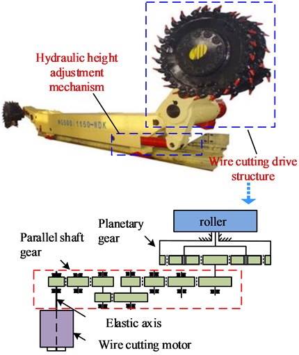
The coal shearer drums height adjustment system mainly includes a drum cutting transmission mechanism and a height adjustment mechanism. The drum cutting mechanism is composed of a cutting motor, a gear transmission system, a drum, etc.; the hydraulic height adjusting mechanism is composed of a driving motor, a control system, a hydraulic motor and a hydraulic cylinder. The structure diagram of the “machine-electric-liquid” coupling drum height adjustment system is shown in Fig. 1.
2.2. Increase control system transfer function
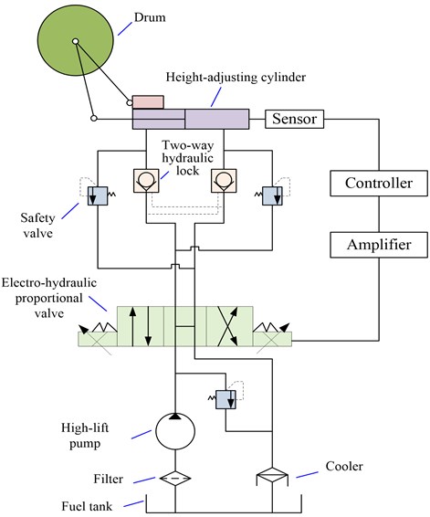
The hydraulic control circuit diagram of the coal shearer machines height adjustment system is shown in Fig. 2. It includes the electro-hydraulic proportional valve, height-adjusting pump, height-adjusting cylinder and two-way hydraulic lock. When the coal smasher height adjustment system is working, the controller gives the control voltage (the input quantity of the system), and after the amplifier is amplified, the current control signal is obtained, and the throttle area is controlled to change accordingly. Thereby changing the flow rate of the system to control the trajectory and lifting speed of the adjusting drum. The displacement sensor is used to detect the displacement of the cylinder piston, and the signal is converted and compared with a given target signal to form a closed loop control system.
Fig. 1Structure diagram of height adjusting system of Mechanical-Electro-hydraulic coupling drum
According to the force balance equation of the drum height-adjusting cylinder and the flow continuity equation of the cylinder [17], the external load disturbance during the piston movement is ignored, and the closed-loop transfer function of the servo valve of the coal-fired electro-hydraulic proportional-increasing system is as follows:
Among them: ωh=√4βeAp2/Vtm, ξh=(Kce√βem/Vt+Bp√Vt/16βem)/Ap. Where Xp is the displacement of the piston of the cylinder; U is the control voltage signal; Ap is the effective area of the piston inside the cylinder; Kq, Ka and Ksv are the flow gain, amplifier gain and proportional valve gain; ξh and ωh are the damping ratio and natural frequency of the system; Vt is the total compression volume of the hydraulic cylinder; βe is the effective volume elastic modulus; m is the total mass of the piston and the load converted to the piston; Bp is the damping coefficient of the moving parts such as the piston and the load.
2.3. State space model
According to the transfer function, the system state space equation is:
In the middle:
C=[100],D=[000]T,X=[xp˙xp¨xp]T.
Fig. 2Hydraulic control circuit of coal shearer height adjusting system
Define r as the signal for the given position. If the deviation e of the system is a state variable, then:
According to Eqs. (3) and (1), the state space model of the electro-hydraulic proportional servo system based on the deviation variable is obtained as follows:
In the formula:
3. Approaching law sliding mode controller design
When designing the sliding mode variable structure controller, not only the sliding mode motion is expected to have ideal motion characteristics, but also the system state point is expected to have some ideal quality of the approaching motion from any initial state to the switching surface to the switching surface. The generalized sliding mode can only guarantee that the moving point reaches the switching surface within a limited time, and there is no regulation on the arrival process [18]. The approaching law is a sliding mode control method suitable for engineering applications. It can analyze the position of the system state point in the sliding mode switching surface, and also design the whole approaching process. Therefore, the approaching law sliding mode control method with the implement easily sliding mode control law, this paper chooses the approach law to design the sliding mode controller.
The basic steps of designing a coal shearer to increase the proximity law-sliding mode controller include two parts:
1) Using the coal shearer to adjust the state space equation of the system based on the deviation variable, design the switching surface , so that the sliding mode is progressively stable and has good dynamic quality;
2) Design the sliding mode control function to satisfy the sliding mode reachability condition, thereby forming a sliding mode region on the switching surface and making the system stable.
3.1. Sliding mode switching surface design
Select the sliding surface switching function:
The exponential approach law expression is:
If the generalized sliding mode condition is satisfied at the same time, when , ; ; When , , . In the formula, is the initial value of the switching function , is the approaching speed index, is the arrival speed, and is the time.
3.2. Design of sliding mode control function
To get the near-law control, there are:
where is the chosen approach law.
For the electro-hydraulic proportional servo system to select the function switching control strategy, then:
According to Eqs. (4) and Eqs. (5):
When the generalized sliding mode condition is satisfied , according to Eq. (8) and Eq. (9):
According to Eq. (6) and Eq. (9):
According to Eq. (11), the sliding mode control function is:
Construct the Lyapunov function , then:
It can be seen from the above formula that the system designed is stable in accordance with the existence and accessibility conditions of the sliding mode.
4. Simulation analysis of trending close-law sliding mode control
4.1. Establishment of hydraulics analog simulation model
In the simulation study of the dynamic performance of the electro-hydraulic servo system, the simulation model is established based on the derived system transfer function of Simulink software, and the system is improved according to the simulation results until the dynamic characteristics meet the requirements. However, such models do not consider nonlinear factors such as pipe connection, coulomb friction, and hydraulic oil source and so on, which are too idealistic. And there are errors compared with the actual situation which cause the simulation results are not accurate enough. In addition, the traditional simulation method also has the disadvantages of cumbersome and not intuitive modeling process.
Hydraulics Analog is a professional module for hydraulic drive modeling and simulation in Simulink software. The simulation is based on the construction of near-real components, simulating the actual system to build a simulation block diagram, extending the capabilities of physical modeling and simulation in Simulink. The physical network control model with hydraulic and mechanical components established by this module is closer to reality, which can effectively improve the efficiency and accuracy of the design.
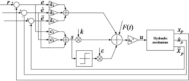
The Hydraulics Analog physical simulation model is constructed according to the selected parameters of the hydraulic system components and considering the nonlinear factors such as pipe connection, viscous damping, elastic load, external load, Coulomb friction and hydraulic oil source. Based on this model, the simulation model of the sliding mode controller is established according to the governing law of the system's transfer function and the design of the law of sliding mode control. The control model is shown in Fig. 3. The matrix , where, denotes the force of the cylinder piston. The logical structure of the approaching sliding mode controller is shown in Fig 4.
Fig. 3Simulation model of sliding mode control for height adjusting system of coal shearer
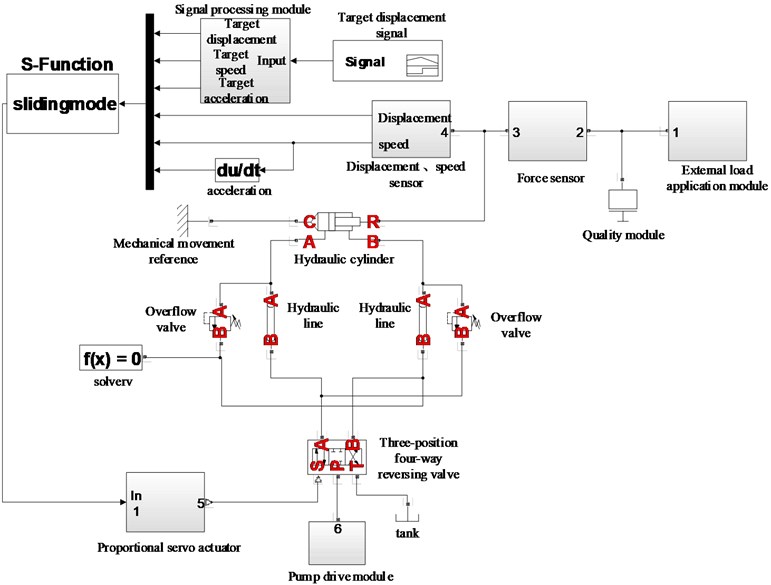
Fig. 4Logic structure diagram of sliding mode controller for reaching law
4.2. Simulation analysis
The controller steps sinusoidal signal and keeps track of the performance of the test, while the state of the system according to the equation, conventional PID controller simulation comparison.
The main simulation parameters are as follows: total leakage coefficient of hydraulic cylinder 1, flow coefficient 0.7; hydraulic cylinder friction 350 N; effective area of piston 0.03 m2; oil modulus of elasticity 800 MPa, oil density 900 kg/m3, damping ratio 0.2, natural frequency 26 Hz; flow gain 4, amplifier gain 6, proportional valve gain 0.06, the total mass of the piston and load converted to the piston 52 kg, damping coefficient of moving parts such as pistons and loads 0.7N·s·m-1, 3.2, 0.28, 13.
From Fig. 5(a) is a step signal tracking and Fig. 6(a) is error versus apparent, the process of tracking PID control system and the reaching law sliding mode control rise time is substantially the same, but the overshoot is 6 % under the PID control of the system, the oscillation frequency of the system is high and the oscillation amplitude is large, the system tends to be stable for a long time, and the error after the stability is larger than the target value; the overshoot of the system under sliding mode control is only 2.5 %. The oscillation frequency of the system is low and the oscillation amplitude is small, the system tends to be stable in a short period of time, and the error after the stabilization and the target value is also small. Therefore, the approaching sliding mode controller is superior to the traditional PID controller in terms of system speed, stability and accuracy. Hence, the sliding mode controller has better control effect.
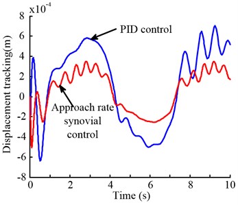
From Fig. 5(b) and Fig. 6(b) show that the tracking process approach system error than the sliding mode control law PID control error in the system to be smaller, and the initial oscillation amplitude is large under the PID control in system, the tracking error in the tracking process is large and the change is huge; the initial oscillation amplitude of the system under sliding mode control is small, and the tracking error in the tracking process is little and the change is small. It can also be seen from the tracking simulation of the sinusoidal signal that the control effect of the sliding mode controller is better and more ideal.
Fig. 5Comparison of PID control and sliding mode control tracking simulation in heightening system
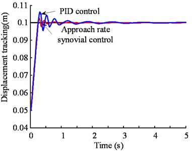
a)
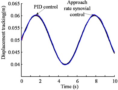
b)

Fig. 6Comparison of tracking error between PID control and sliding mode control in height adjustment system
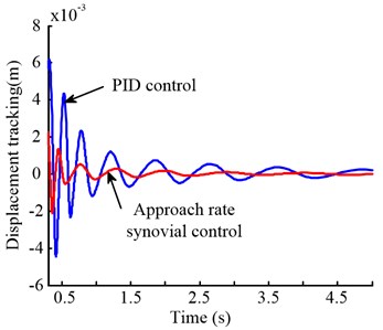
a)
b)

Fig. 7Comparison of tracking simulation for adjusting system with external impact load
a) PID control
b) Approaching law sliding mode control

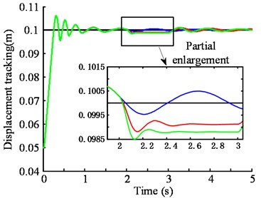
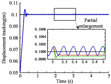
Fig. 7 shows the comparison of the control effects of the system when the system is under no load and subjected to different applied loads. The system is subjected to additional load shocks in 2-3 seconds. It can be seen from the figure that the system under PID control is obviously affected and the displacement output has a huge deviation, and the system is almost unaffected under the control of the sliding mode control. There is almost no deviation from the displacement output. Seen from the enlarged view, the PID control of the system when subjected to an impact load is the amount of displacement of the output variation rate of the system under the sliding mode control deviation rate of 7 times, sliding mode control system only occurs to 0.2 % deviation. Therefore, the near-law sliding mode controller can effectively overcome the disturbance impact on the external load, and has stronger adaptability to complex working conditions, and is especially suitable for the height control of the coal shearer under the harsh environment and the heavy load sudden working condition.
Fig. 8Output torque of cutting motor under different control methods
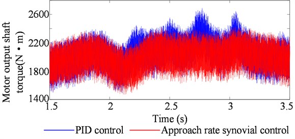
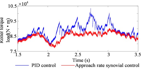
Fig. 8 and Fig. 9 show the change process of the output shaft torque and the drum torque load of the cutting motor when the drum is disturbed during the cutting process of the coal-rock interface. It can be seen from the figure that the drum height is more stable and accurate when it is controlled by the approaching law sliding mode. Therefore, the output shaft torque of the cutting motor and the drum load ratio are more stable and smaller when using the control of PID, and the cutting part of the coal shearer is cut. The drive system will have less impact and will help reducing damage to the various components of the drive train. Because the height of the drum controlled by the approaching law-sliding mode is almost unaffected by the disturbance of the external working conditions, and can still maintain the original trajectory operation, avoid cutting to the roof rock layer, reduce the load impact and the damage caused to the system. The control process is more stable. Under control of PID, the height of the drum cannot resist the external disturbance. The disturbance causes the drum height to change greatly, thus cutting the roof rock layer, increasing the system load and causing greater damage to the cutting section transmission system. Therefore, the drum height adjustment system is more suitable for adopting the law of sliding mode control, and its anti-disturbance ability is stronger. It not only can realize the fast, accurate and stable drum height control, but also help protect the coal shearer cutting system.
Fig. 9Drum torque load under different control methods
5. Variable speed reaching law sliding mode controller design
5.1. Study characteristics reaching law
Sliding mode control can not only improve the system's rapidity, stability and accuracy, but also as a nonlinear control method can effectively overcome the system uncertainty and external load disturbance impact through structural adjustment and change. But the sliding mode adopts the discontinuous control law makes the system need to switch back and forth between different control logic, which is easy to cause chattering unfavorable to the system and affecting its control effect. The chattering generated during the suppression control process have become the research hotspot of sliding mode control.
Fig. 10Comparison of control effects under different ε values
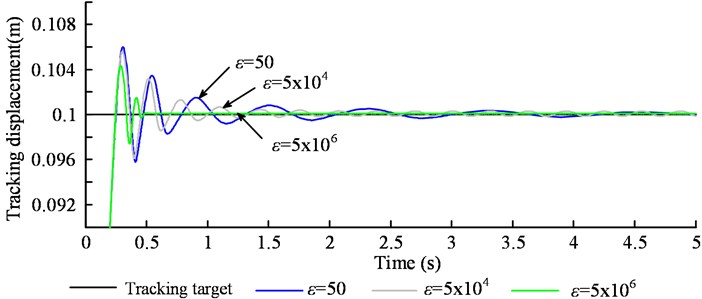
For the exponential approaching law sliding mode controller, the rapid selection of the approaching segment and the suppression of the chattering of the sliding segment can be ensured by the appropriate selection of the parameters and . generally, takes a larger value to ensure a faster approach to the sliding surface, and the quality of the sliding mode is mainly affected by . Fig. 10 shows the same parameters , different parameters under control effect comparison chart, Fig. 11 is different parameters under control of the handover procedure function which characterizes the size of the system chattering. From Fig. 10 clear, the system has the smallest overshoot, and the error with the target value is the smallest and the precision is the highest when 5×10⁶. But in Fig. 11(c), (d) can be seen the chattering situation is also the largest, which increases the energy consumption, affect the stability, increase the control difficult. In Fig. 10 can be seen, when 50, the overshoot of the system is the largest, and the response speed of the system is also slow. It tends to be stable for a long time and is stable and has a large error with the target value. However, it can be seen from Fig. 11(a) that the chattering situation is the smallest. Therefore, the larger the , the better the speed and accuracy of the system, but the greater the chattering situation, the more difficult the system is to control.
Fig. 11Different ε values under the sliding mode control process switching functions
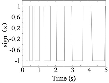
a)50 partial enlargement
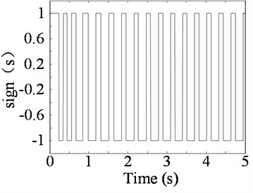
b)5×10⁴ partial enlargement
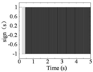
c)5×10⁶ partial enlargement
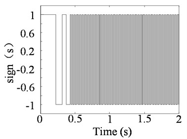
d) 5×10⁶ partial enlargement
5.2. Variable speed reaching law based on fuzzy control
The law of the reach law obtained from Fig. 10 and Fig. 11 is known, in order to control sliding mode index reaching law chattering generated effectively suppressed, reaches the sliding surface value to be small. But at this time if smaller will extend the time that the moving point enters the sliding mode area, resulting in poor dynamic quality of the sliding mode motion. Increasing may be to accelerate the speed of approach, but larger ε increases the strength control system demand value. Conversely, decreasing ε means that the approach speed is reduced, and the motion point takes longer to enter the sliding mode region. Therefore, in the approaching process, when the system movement point is far away from the sliding surface, a strong control amount can be applied to ensure the approaching process is accelerated; the control amount is weakened when approaching or reaching the sliding surface, so as to reduce the chattering.
In other areas, the jitter sensitivity of a digital parameter adaptive tracking control system was studied by Michael Short in the way of using precise software-in-the-loop computational simulations, which presents some useful insights into the practical complexities when innovating adaptive real-time tracking control systems [19]. Therefore, in this paper an adaptive shifting approach law is designed to collect and calculate the distance and exit speed of the state track point from the sliding surface in real time, and select a reasonable control quantity to obtain better dynamic quality of sliding mode motion. In the engineering practice, the fixed parameter can be selected, and the method of dynamically adjusting the arrival speed ε can ensure the fastness of the approaching motion and the ability of the system to resist external disturbances, and effectively suppress the chattering of the system to ensure the steady-state accuracy.
Therefore, this paper will design a two-dimensional fuzzy optimization controller with two inputs and one output, with the switching function and its derivative as the input quantity, and the fuzzy parameter optimization strategy with the arrival speed as the output, in order to realize the shifting of the moving point reaching rate. The basic rule is that when the moving point is far away from the sliding surface, a larger is taken, and when the moving point is closer to the sliding surface, a smaller is taken. The speed response is improved when the sliding mode is out of plane and the ability is raised of the system overcomes the perturbation and external interference. To soften the amount of control to eliminate chattering when the sliding surface is reached. And the control objective is to make the sliding mode switching function zero.
The fuzzy sets of the input and output of the fuzzy controller are:
Design the fuzzy rule table shown in Table 1.
Table 1Arrival speed fuzzy rule
NB | NS | ZR | PS | PB | |
NB | PB | PB | PM | PM | PM |
NS | PM | PM | PM | PS | PS |
ZR | ZB | ZB | ZS | ZB | ZB |
PS | PS | PS | PM | PM | PM |
PB | PM | PM | PM | PB | PB |
5.3. Simulation analysis
Establishing sliding mode control model of variable speed reaching law based on Hydraulics Analog sliding mode control. the simulation results are shown in Fig. 10. From Figure understood, use of variable speed reaching law sliding mode control system having a less than 50 at small reaching law control 33 % of small overshoot, fast response speed and can stabilize rapid after stabilization target value error is small, the response speed and precision with 5×10⁶ when a large reaching law control considerable. While in Fig. 13, Fig. 14 can be seen, the system of variable speed reaching law the chattering vibration is much smaller than that of the controller with large approach law, so the control effect of the variable speed reach sliding mode control is better than the sliding mode control under the fixed approaching law, which realizes the fastness and accuracy of the approaching motion. It also ensures the ability to resist external disturbances of the system and at the same time effectively suppresses the chattering of the system to achieve the purpose of ensuring steady-state accuracy, and is more suitable for the control of the height of the coal shearer drum.
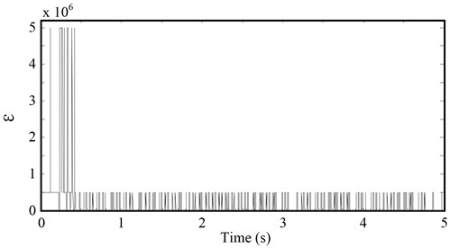
Fig. 15 shows a reaching law sliding mode control under the shift ε change process, when the far point distance movement sliding surface has a large , the movement distance point closes sliding surface has a smaller . Thereby, the sliding mode control of the shifting approach law is realized.
Fig. 12Comparison of control effects under different approaches
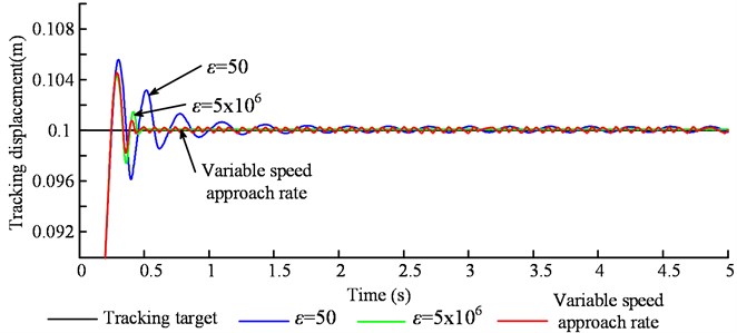
Fig. 13The sliding mode control function of the switching process when ε= 5×10⁶
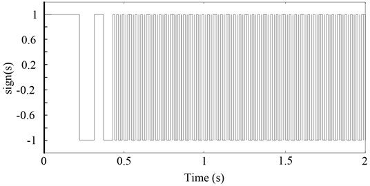
Fig. 14The sliding mode control process switching functions when ε= 50
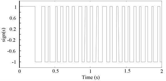
Fig. 15Shift reaching the sliding mode control law ε of change process
6. Conclusions
The working environment of the coal shearer machine is poor and the coal shearer conditions are complicated. There is external load interference of heavy load mutation conditions. For the hydraulic adjustment system of the electro-hydraulic proportional servo system, it is difficult to achieve fast and accurate control using traditional PID control. Aiming at the problems of poor robustness and low control accuracy of traditional drum height control methods, this paper proposes a sliding mode control method for drum height adjustment based on the variable speed reach law. Details as follows:
1) The mathematical model of the height adjustment cylinder of the shearer was established, and the sliding mode switching function and its derivatives containing the deviation variables were derived. The control effect of the proposed sliding mode control method of drum height adjustment based on reaching law and traditional PID control method is compared and analyzed. The results show that compared with the traditional PID control, the sliding mode control of the roller height adjustment system using the approach law has stronger anti-disturbance capability.
2) In order to further suppress the chattering phenomenon of the sliding mode control of the approach law, combined with the fuzzy parameter optimization strategy to achieve dynamic adjustment of the arrival speed, the research results show that the sliding mode control strategy proposed by the variable speed reach law cannot only realize the hydraulic height adjustment system fast, stable and accurate height adjustment control, but also effectively overcome the uncertainty of the system and the impact of external load disturbances. It has strong adaptability to complex working conditions and can effectively suppress the chattering of traditional approach law sliding mode control.
References
-
Wang Z. B., Xu Z. P., Dong X. J., et al. Self-adaptive adjustment height of the drum in the shearer based on artificial immune and memory cutting. Journal of the China Coal Society, Vol. 34, Issue 10, 2009, p. 1405-1409.
-
Liu C. S., Yu X. W., Ren C. Working Mechanism of Drum Shearer. Harbin Engineering University Press, Heilongjiang, China, 2010.
-
Tan C., Xu R. X., Wang Z. B., et al. An improved genetic fuzzy logic control method to reduce the enlargement of coal floor deformation in shearer memory cutting process. Computational Intelligence and Neuroscience, Vol. 2016, Issue 2016, 2016, p. 3973627.
-
Fan Q. G., Li W., Wang Y. Q., et al. An algorithm of shearer memory cutting based on eye-Markovian model. Journal of Central South University (Science and Technology), Vol. 42, Issue 10, 2011, p. 3054-3058.
-
Mi J. P., Tan C., Zhang L. L., et al. Research on the memory cutting path of shearer based on genetic algorithm. Journal of Coal Science and Engineering, Vol. 16, Issue 3, 2010, p. 333-336.
-
Xu Z. P., Wang Z. B. Modeling and simulation on shearer self-adaptive memory cutting. Procedia Engineering, Vol. 37, Issue 4, 2012, p. 37-41.
-
Xu Z. P., Wang Z. B., Mi J. P. Shearer self-adaptive memory cutting. Journal of Chongqing University, Vol. 34, Issue 4, 2011, p. 134-140.
-
Liu C. S., Kai J., Qiu Y. A new grey correlation degree computation method of shearer drums by cutting memory program controlling. Journal of China Coal Society, Vol. 31, Issue 5, 2006, p. 666-669.
-
Liu C. S., Qiu Y., Li C. H. Simulation of shearer drum cutting with memory program controlling by fuzzy control. Journal of China Coal Society, Vol. 33, Issue 7, 2008, p. 822-825.
-
Liu C. S., Chen J. G. Adaptive fuzzy PID control simulation on memory-cutting of single demonstration cutter shearer. Journal of Liaoning Technical University (Natural Science), Vol. 32, Issue 1, 2013, p. 85-88.
-
Wang Z. B., Xu Z. P., Dong X. J. Self-adaptive adjustment height of the drum in the shearer based on artificial immune and memory cutting. Journal of China Coal Society, Vol. 34, Issue 10, 2009, p. 1405-1409.
-
Fan Q. G., Li W., Wang Y. Q., et al. An algorithm of shearer memory cutting based on grey-Markovian model. Journal of Central South University (Science and Technology), Vol. 42, Issue 10, 2011, p. 2913-2918.
-
Tian M. Q., Xin Z. D. Automatically adjusting the predictive control system of shearer based on memory cutting. Coal Mine Mechanics, Vol. 6, 2002, p. 29-32.
-
Zhang F. J. Research on Memory Cutting Control Strategy of Electric Haulage Shearer. Coal Science Research Institute, Beijing, China, 2007.
-
Zhang Y. F. Research on tracking and control strategy of drum shearer. M.E. dissertation, Zhejiang University, Zhejiang, China, 2014.
-
Liu F. X., Cui J., Li Y. M., WANG, G. R. Research on hydraulic height adjustment for shearer drum with adaptive fuzzy differential and integral SMC based on AFSA-ACALiu. Machine Tool and Hydraulics, Vol. 43, Issue 8, 2015, p. 141-144.
-
Xu E. B. Research on Electro-Hydraulic Portioned System of Shearer Automatic Drum Height Adjustment Based on AMESim. AnHui University of Science and Technology, AnHui, China, 2013.
-
Gao W. B. Theory and design method of variable structure control. Science Press, Beijing, China, 1998, p. 241-248.
-
Michael Short, Fathi Abugchem On the Jitter Sensitivity of an Adaptive Digital Controller: A Computational Simulation Study. International Journal of Engineering and Technology Innovation, Vol. 9, Issue 4, 2019, p. 241-256.
About this article
This project was funded by the National Natural Science Foundation of China (Grant No. 51805061), the National Key R&D Program of China] (Grant No. 2018YFB0105402), the Chongqing Natural Science Foundation (Grant No. cstc2019jcyj-msxmX0733), the Scientific Research Project of Chongqing Education Commission (Grant No. KJQN201901115) and Scientific Research Foundation of Chongqing University of Technology.

