Abstract
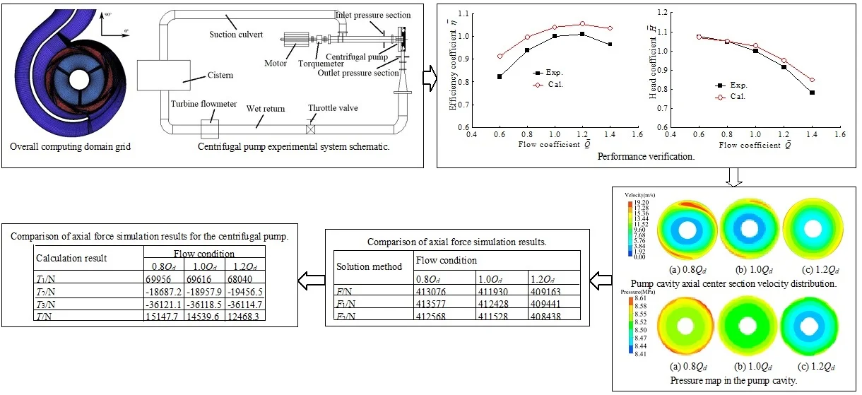
At three flow conditions (0.8Qd, 1.0Qd, and 1.2Qd), the centrifugal pump cavity with front inducer was expanded at 0°, 90°, 180°, and 270°, and a flow path analysis of the axial cross section at the four angles was performed. This revealed that the circumferential and radial velocities of the liquid in the pump cavity along the same angle at different radii follow an axial and radial variation law to different degrees. The pump cavity center axial liquid velocity component along the radial distribution at different angles was analyzed, and liquid pressure in the pump cavity along the radial distribution was numerically analyzed from different points of view. The mean pump cavity pressure was plotted along the radial distribution curve, and a detailed numerical calculation of the axial force of the centrifugal pump and pump cavity was developed. The influence of flow conditions on the liquid flow mechanism and axial force characteristics in the pump cavity was thoroughly discussed. The results showed that liquid flow in the centrifugal pump cavity with the front inducer is mainly restricted by the main flow of the volute. The liquid eddy current in the pump cavity is mainly concentrated near the volute and the hub at 90° and 180° angles, and the higher the flow rate, the larger is the area of the side vortex of the impeller-cover plate, and the smaller is the area of the side vortex of the pump-cover plate. When the flow rate increases, the flow direction of the eddy current at the same angle in the pump cavity remains unchanged, but when the flow rate becomes too high, the flow direction of the eddy current at the same angle in the pump cavity changes. When the range of circumferential and radial partial velocities decreases, the rotational angular velocity increases, and the pressure decreases. At low flow rate, the larger the area of the volute corresponding to the pump cavity, the higher the speed becomes. The axial force in the pump cavity is the most important factor determining the axial force of the centrifugal pump.
Highlights
- At three flow conditions (0.8Qd, 1.0Qd, and 1.2Qd), the centrifugal pump cavity with front inducer was expanded at 0°, 90°, 180°, and 270°, and a flow path analysis of the axial cross section at the four angles was performed.
- The pump cavity center axial liquid velocity component along the radial distribution at different angles was analyzed, and liquid pressure in the pump cavity along the radial distribution was numerically analyzed from different points of view.
- The mean pump cavity pressure was plotted along the radial distribution curve, and a detailed numerical calculation of the axial force of the centrifugal pump and pump cavity was developed.
- The influence of flow conditions on the liquid flow mechanism and axial force characteristics in the pump cavity was thoroughly discussed.
- This paper selects the semi-open impeller centrifugal pump with front inducer as the research object and analyzes the different working conditions.
- The numerical analysis of the centrifugal pump based on grid-independence verification of the model calculation domain and an external characteristic parameter test verification.
1. Introduction
The axial force of a centrifugal pump is one of the most important factors affecting its service life and stable operation [1-3]. In calculating axial force, an empirical and semi-empirical theoretical formula is usually employed. In deriving this formula, it is considered that the pump cavity liquid has no radial leakage flow and that the liquid in the pump cavity rotates at one-half the rotational angular velocity of the impeller [4, 5]. Debuchy [6] studied a turning static disk system core of cavity flows using experimental measurements and carried out a comparative analysis and theoretical calculation. Salvadori [7] performed a CFD numerical simulation of a multistage centrifugal pump and pointed out that to calculate the centrifugal pump axial force accurately, a detailed analysis of the flow characteristics of the fluid on the side of the impeller cover-plate cavity must be included. Matsui [8] used a numerical simulation method to model the back and side cavity flow in a centrifugal pump impeller to study the effects of axial force on hydraulic performance. Another experimental study [9, 10] according to traditional theory assumed that the liquid in the pump cavity obeyed the flow-velocity calculation formula for axial force, but this did not tally with the actual test results. The pump cavity fluid-flow characteristic has a direct impact on the force on the centrifugal pump impeller cover plate, and this cover-plate force is a major component of axial force [11, 12]. Due to the imperfect state of knowledge of the liquid flow mechanism in the pump cavity, it is impossible to accurately calculate and balance the axial force of the centrifugal pump [13, 14].
Research on centrifugal pumps with front inducer mainly focuses on the internal flow characteristics of the inducer [15-17]. Compared with closed impellers, in semi-open centrifugal impellers, the impeller has no front cover, but only a rear cover. In this situation, the pressure imbalance on the front and rear sides of the impeller is more serious, and the axial force generated is usually larger, which is more harmful to centrifugal pump operation [18, 19]. Therefore, this paper selects the semi-open impeller centrifugal pump with front inducer as the research object and analyzes the 0.8Qd, 1.0Qd, and 1.2Qd working conditions based on grid-independence verification of the model calculation domain and an external characteristic parameter test verification. The liquid flow characteristics at the points of the front inducer centrifugal pump cavity at 0°, 90°, 180°, and 270° angles. were used to investigate the liquid in the pump cavity at the 0° angle at 0.6R, 0.7R, 0.8R, and 0.9R (R is the radius of the pump cavity) and at the 0.8R radius at 90°, 180°, and 270° angles, as well as the partial velocity distribution along the axial direction. The radial distribution of the liquid circumference at the axial center of the pump cavity and the radial partial velocity along the 0°, 90°, 180°, and 270° angles were also analyzed. Numerical analysis of the liquid pressure in the pump cavity showed that its average value is distributed in the radial direction and that the axial force of the centrifugal pump and the pump cavity can be calculated numerically. A detailed analysis of the fluid flow mechanism and axial force characteristics in the cavity of a centrifugal pump is of great significance to calculating and balancing the centrifugal pump axial force.
2. Research objects and calculation methods
2.1. Research objects
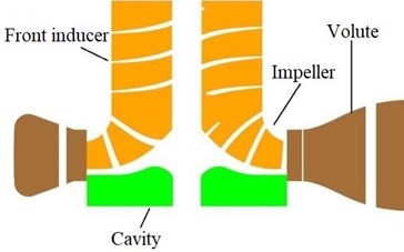
The research object was a centrifugal pump with a front inducer having a design speed of 2950 r/min. The number of inducer blades was 3, and the number of centrifugal impeller blades was 6. The inducer generates equal-pitch axial flow, the inducer hub is cylindrical, and the centrifugal impeller is a semi-open impeller. The geometric model and its components are shown in Fig. 1.
Table 1Design parameters of centrifugal pump
Head H / m | 76 |
Flow Qd / m3·h-1 | 380 |
Speed n/ RPM | 2950 |
Specific speed ns | 136 |
Efficiency η / % | 82.76 |
Impeller hub diameter Dh / mm | 75 |
Inlet diameter D1 / mm | 200 |
Impeller diameter D2 / mm | 259 |
Fig. 1Overall flow channel profile of centrifugal pump
2.2. Numerical calculations and boundary conditions
The ANSYS CFX software was used for numerical simulation, and the working medium was clear water. The SST turbulence model was used for numerical calculation of the overall centrifugal pump model with the front inducer. The flow mode in the pump was incompressible and otherwise normal steady-state flow.
The boundary condition were that the inlet boundary was a given total pressure and that the outlet boundary was a given mass flow rate. By adjusting the outlet flow rate, the corresponding flow conditions were met, and the solid wall surface was adiabatic without slippage. The convergence criterion is that the maximum residual is less than 10-5.
2.3. Grid division and verification of independence
The semi-open impeller centrifugal pump model selected in this study is composed of an inducer, a high-center impeller, a volute, and a pump cavity. The calculation domain grid is divided by ANSYS ICEM CFD. The overall grid (a structured grid) is divided by a structured grid, and the boundary layer region is encrypted. The frozen rotor method is used to transfer data between the rotation and stationary domains to induce the channel grid. The grid quality of each part is guaranteed above 0.3. The number of grid nodes in front inducer channel is about 1.15 million, the number of grid nodes in the centrifugal impeller channel is about 1.3 million, the number of grid nodes in the volute is about 1.31 million, the number of grid nodes in the pump cavity is about 240,000, and the total number of grid nodes in the calculation model is about 400 million.
Because this paper mainly studies the liquid flow mechanism in the pump cavity of the centrifugal pump, grid encryption is used. By adding about 50,000 units to the grid of the cavity calculation domain each time, the change in the number of grid nodes at the design operating point is obtained. The relationship between pump performance parameters achieves the purpose of grid independence verification, as shown in Fig. 2. The efficiency coefficient ˉη and the head coefficient ˉH are the ratios between the numerical calculation results (η1, H1) and the design results (η, H), which are defined as:
Fig. 2Independence verification of the number of grid cells
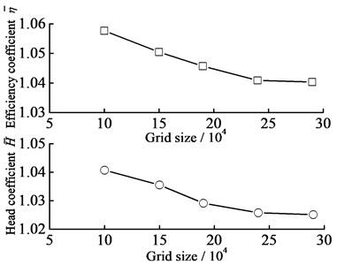
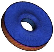
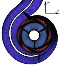
Fig. 2 shows that when the number of grid cells in the pump cavity area was increased from 240000 to 290000, the efficiency coefficients and head coefficients remained basically unchanged. This shows that the efficiency and the head are independent of the number of grid cells when that number is 240,000. The whole grid-computing domain, including the centrifugal impeller, pump cavity, and centrifugal pump, is shown in Fig. 3.
Fig. 3Calculation model of centrifugal pump with a front inducer
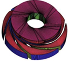
a) Centrifugal impeller grid
b) Pump cavity grid
c) Overall computing domain grid
2.4. External characteristic test verification
In the closed test bed of a Pump laboratory, a pump performance test was carried out. When the working fluid was clean water at room temperature (23 °C), the schematic diagram of the test device was as shown in Fig. 4.
Fig. 4Centrifugal pump experimental system schematic
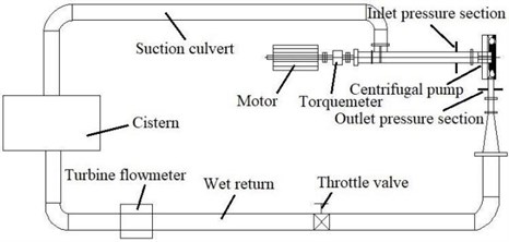
The actual pump flow rate was measured by the LWGY-DN150 turbine flowmeter, the motor speed and output torque were measured by the HLT-138 torque measuring instrument, and the pump inlet and outlet pressures were calculated using the MIK-Y190 pressure meter on the inlet and outlet sections respectively.
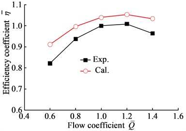
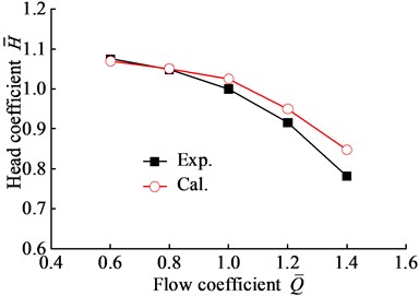
Fig. 5 shows a comparison curve between the numerical results of the performance calculation and the test results. The efficiency, head, and flow coefficients were obtained by taking the efficiency, head coefficient, and flow rate measured in the test as a benchmark.
Fig. 5Performance verification
a)η-Qd
b)H-Qd
As can be seen from Fig. 5, when the flow coefficient increased from 0.4 to 1.6, the numerical calculation results for the efficiency coefficient and the test results showed the same trend of increasing and then decreasing, but the numerical calculation results for the head coefficient and the test results showed a decreasing trend. Among these, at the design condition with a flow coefficient of 1.0Qd, the relative errors between the numerical calculation results for the efficiency and head coefficients and the test results were 3.9 % and 2.5 % respectively. This shows that the numerical calculation results for efficiency and head were consistent with the change trend of the test results. In other words, the two are basically consistent, which can provide a reliable foundation for the following research.
3. Analysis of pump cavity flow mechanism
3.1. Pump cavity flow characteristics and analysis
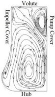
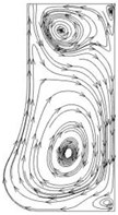
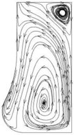
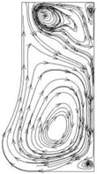
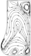
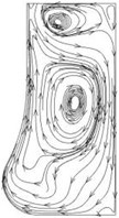
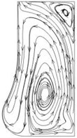
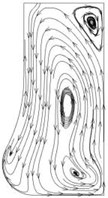
In this study, to investigate liquid flow in the pump cavity of the centrifugal pump with front inducer, the flow profile of the liquid flow line in the pump cavity along the four angle sections of 0°, 90°, 180°, and 270° was examined under three flow conditions: low flow rate (0.8Qd), design flow rate (1.0Qd), and high flow rate (1.2Qd), as shown in Figs. 6-8.
Fig. 6Flow line distribution in the radial section of the pump cavity at the 0.8Qd operating point
a)α=0°
b)α=90°
c)α=180°
d)α=270°
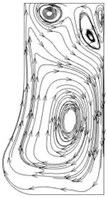
Fig. 7Flow line distribution in the radial section of the pump cavity at the 1.0Qd operating point
a)α=0°
b)α=90°
c)α=180°
d)α=270°
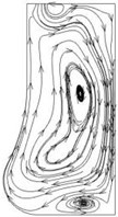
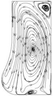
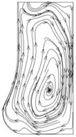
Fig. 8Flow distribution in the radial section of the pump cavity at the 1.2Qd operating point
a)α=0°
b)α=90°
c)α=180°
d)α=270°
Figs. 6-8 show that at the low-flow working condition (0.8Qd), there is a clockwise eddy current rotating in the corner area between the volute and the pump cover, with liquid flowing from the pump cavity to the volute at the corner area between the volute and the impeller at the 0° and 180° angles. At the same time, there is a counterclockwise vortex at the axial center near the wheel load. There is a source of counterclockwise rotation at the axial center near the volute, and the liquid flows from the volute to the wheel at the corner of the volute and the impeller at the 90° and 270° angles. There is also a vortex of clockwise rotation in the corner of the volute and the pump cover, but the intensity of the vortex in the corner is lower than that in the vortices at 0° and 180°. At the same time, there is a clockwise vortex at the axial center near the wheel saddle. In the wheel and pump-cover angle area, the intensity of the vortex is lower. At the design flow rate (1.0Qd), there is a clockwise eddy current in the volute and the pump-cover angle area, and the liquid flows from the pump cavity to the volute in the volute and impeller angle areas at an angle of 0°. At the same time, eddy currents are generated in the axial center of the pump cavity, near the wheel valley and the pump cover the angle area, and the eddy currents rotate counterclockwise at an angle of 0°. At an angle of 180°, there is a clockwise swirl in the corner of the volute and the pump cover, and the liquid flows from the wheel to the volute at the corner of the volute and the impeller. At the same time, there is a counterclockwise vortex near the wheel. At the 90° and 270° angles, there is a counterclockwise vortex at the center of the axial length near the volute, and the liquid flows from the volute to the wheel valley at the corner of the volute and the impeller. The difference is that at an angle of 90°, the volute and the pump-cover angle area also have a clockwise rotating eddy current, but the intensity of the eddy current in the angle area is lower than in the 0° and 180° angle areas. At an angle of 270°, the volute and the pump cover produce two eddy currents in opposite directions. A clockwise swirl is generated near the axial center of the pump cavity at two angles. At the high flow rate (1.2Qd), there is a weak eddy current near the volute, which generates another eddy current near the axial center of the pump cavity and the wheel view at an angle of 0°. At an angle of 180°, vortices are generated near the axial center of the volute and the pump cavity.
Figs. 6-8 show that when the flow rate increases from 0.8Qd to 1.20Qd, the eddy current around the top wheel at an angle of 0° diverges into two parts, and there is an eddy current near the wheel load. Part of the vortex center gradually moves towards the volute, and the other part moves towards the wheel load and finally forms an eddy current near the tip of the wheel. The eddy current intensity between the volute and the pump cover gradually decreases and finally disappears. At the 90° and 270° angles, the vortex intensity near the volute becomes smaller and smaller until it disappears, and the vortex center near the hub moves towards the volute. When the flow is 1.2Qd, the vortex intensity at the volute and the pump cover is the highest.
To facilitate analysis of the relationship between the liquid velocity in the side cavity of the rear cover of the impeller and the rotational velocity of the impeller, a dimensionless quantity was introduced to analyze the distribution of circumferential and radial velocity along the axial and radial direction, which was defined as:
where ˉvu is the dimensionless circumferential speed, ˉvr the dimensionless radial velocity, ˉs the dimensionless axial length factor, ˉr the dimensionless radial length factor, vu the pump cavity closed-point circumferential velocity (m/s), vr the radial velocity at the inner measuring point in the cavity (m/s), ω the impeller rotating angular velocity (rad), s the measuring point of the axial length from the impeller cover lateral wall to the pump cover lateral wall (m), δ the axial length between the impeller cover and the pump cover (m), r the pump cavity radius at the inner point (m), and r' the pump cavity radius (m).
3.2. Axial variation law and analysis of pump cavity velocity component
Under the three flow conditions, the radial distribution of liquid flow velocity in the cavity along 0°, 90°, 180°, and 270° is shown in Figs. 9-11.
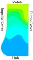
Figs. 9-11 show the speed zones; the zone with speed lower than 5 m/s is designated as the low-speed zone, and the zone with speed higher than 16 m/s is designated as the high-speed zone.
Figs. 9-11 show that at the working point of low flow rate (0.8Qd), the low-speed zone occupies a large area, and there is no high-speed zone at the 0° and 180° angles. At the 90° and 270° angles, the area of the low-speed zone is slightly reduced, but the high-speed zone appears. The high-speed zone is located near the corner of the cover of the volute and the impeller. At the design flow rate (1.0Qd), the low-speed zone is concentrated in the vicinity of the wheel load, and the high-speed zone is distributed in the vicinity of the volute and impeller cover, but the high-speed zone is small, and the flow condition point is small at the 0° and 180° angles. At the high flow rate (1.2Qd) working point and the four angles, the low-speed zone is all concentrated around the hub, and this speed zone is larger than under the previous two working conditions. The high-speed zone is all concentrated around the volute, and the velocity distribution is more even than under the previous two flow conditions. At the 0° and 180° angles, the high-speed zone appears. At the 90° and 270° angles, the area of the high-speed zone is the smallest.
Fig. 9Velocity distribution in the radial section of the pump cavity at the 0.8Qd operating point

a)α=0°

b)α=90°

c)α=180°

d)α=270°
Fig. 10Velocity distribution in the radial section of the pump cavity at the 1.0Qd operating point


a)α=0°

b)α=90°

c)α=180°

d)α=270°
Fig. 11Velocity distribution in the radial section of the pump cavity at the 1.2Qd operating point


a)α=0°

b)α=90°

c)α=180°

d)α=270°
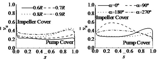
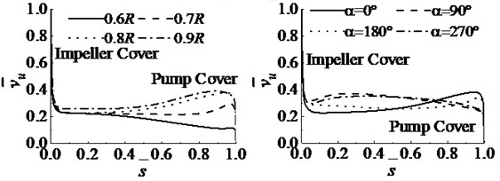
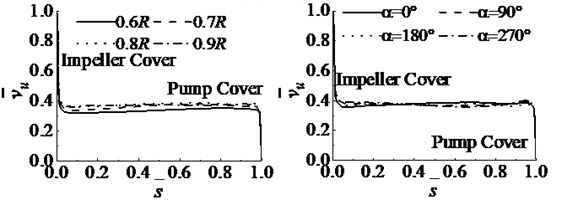
After the above analysis, to further study the characteristics of liquid circumferential and radial flow in the pump cavity at different radii and angles, this article first presents the pump under three flow conditions of 0.8Qd, 1.0Qd, and 1.2Qd. Four radii 0.6R, 0.7R, 0.8R, and 0.9R (R is the radius of the pump cavity) of the liquid in the pump cavity at 0° are examined. The angular, dimensionless circumferential, and radial partial velocities along the axial distribution curve are shown in Fig. 12.
Fig. 12 shows that under the same flow conditions, the liquid in the pump cavity at zero angle is 0.6R, 0.7R, 0.8R, and 0.9R for the four radii R, and at 0.8R, at the four angles 0°, 90°, 180°, and 270°, the dimensionless circumferential velocity component is equal to 1 in the impeller and 0 at the pump-cover wall. The question remains whether at the same angle at different radii, or at the same radius from different points of view, the pump cavity still contains two turbulent boundary layers, but with a smaller core between the two boundary layers along the axial flow. At low flow rate (0.8Qd), at 0°, at 0.6R, 0.7R, 0.8R, and 0.9R (the four radii R), the larger the radius of the dimensionless circumferential velocity, the higher will be the core zone velocity at the same axial distance, and its value is greater than 0.2. The 0.8R at the four angles of 0°, 90°, 180°, and 270°. The dimensionless circumferential velocity varies widely and does not show regularity. Its value is less than 0.6. The circumferential velocity distribution of liquid in the pump cavity does not have axial symmetry. The 0° and 180° angles from the wall of the impeller rear cover to the core of the pump cover at first remain the same. When ˉs> 0.45, the speed rises. At the design flow rate (1.0Qd), when the dimensionless circumferential velocity is ˉs> 0.2 at a 0° angle, the larger the radius, the higher is the speed in the core area. At the working condition, when the dimensionless circumferential velocity is ˉs< 0.2 at a 0° angle, the core zone velocity values of 0.6R, 0.7R, 0.8R, 0.9R are becoming equal. For the four angles at 0.8R radius, the velocity is still not axisymmetric, and the values are all less than 0.4. At angles of 90° and 270°, from the impeller rear cover wall surface to the core area of the pump cover wall, the speed increases at ˉs< 0.2, and when ˉs> 0.2, the speed decreases from the impeller rear cover wall surface to the core area of the pump-cover wall. At high flow rate (1.2Qd), the dimensionless circumferential velocity of 0.6R in the core region at 0° angle is always lower than that of the other radii. When the velocity in the core area for 0.7R is ˉs<0.4, it is lower than those for 0.8R and 0.9R. When the velocity in the core area is ˉs>0.4, the three curves almost coincide, the velocity in the core area for 0.8R and 0.9R is almost stable, and the value is less than 0.37. For the four radial angles at 0.8R, the value is less than 0.45 and lingers around 0.4.
Fig. 12Dimensionless circumferential velocity distributed along the axial direction
a) 0.8Qd
b) 1.0Qd
c) 1.2Qd
Figs. 12 also shows that when the flow rate increases from 0.8Qd to 1.2Qd, the dimensionless circumferential velocity of the core area for 0.6R, 0.7R, 0.8R, and 0.9R at 0° angle decreases first and then increases. At 0.8R radius, the velocity range becomes smaller and smaller until the velocities for the four angles are almost equal. At the design flow rate of 1.0Qd and the high flow rate of 1.2Qd, the four radii (0.6R, 0.7R, 0.8R, and 0.9R) at 0° are significantly different from the dimensionless circumferential component speeds of the four angles (0°, 90°, 180°, and 270°) with a 0.8R radius. At 0.8Qd, the four radii (0.6R, 0.7R, 0.8R, and 0.9R) at 0° are compared with the dimensionless circumference of the four angles (0°, 90°, 180°, and 270°) with 0.8R; the speed difference should be small. This phenomenon occurs because at the same impeller rotational speed at the same angle of volute cross-sectional area, given the ratio of the spiral case liquid to the liquid in the pump cavity (which always remains the same), the influences of the radius and the volute cross-sectional area change at different angles, given that the ratio of the spiral case liquid to the liquid in the pump cavity along the circumferential direction changes.
Fig. 13Dimensionless radial velocity distribution along the axial direction
a) 0.8Qd
b) 1.0Qd
c) 1.2Qd
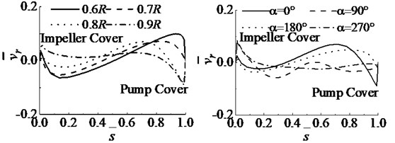
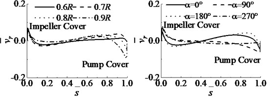
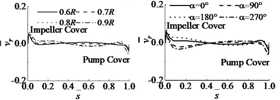
Fig. 13 shows that when the flow rate increases from 0.8Qd to 1.2Qd, the speed fluctuations decrease significantly. The speed at 0.6R, 0.7R, and 0.8R at low flow rate (0.8Qd) and at 0° from the impeller-cover plate to the core area of the pump-cover plate gradually decreases when ˉs< 0.2. When ˉs> 0.2, the velocity gradually increases, whereas at 0.9R, the velocity gradually decreases from the impeller-cover plate to the core area of the pump-cover plate. At 0° and 180° angles at 0.8R, the velocity from the impeller-cover plate to the core area of the pump-cover plate decreases at ˉs< 0.2 and increases at s ̅> 0.2. At the design flow rate of 1.0Qd, at 0.6R, 0.7R, 0.8R, and 0.9R, the speed from the impeller cover to the core area of the pump cover decreases from ˉs<0.2 and increases from ˉs> 0.2. At high flow rate (1.2Qd) at radii 0.6R, 0.7R, 0.8R, and 0.9R, the speed curves almost coincide. The dimensionless radial velocity of the liquid in the pump cavity on the wall of the rotating impeller and the surface of the stationary pump cover are always equal to 0, but the two boundary layers still exist. Under the same flow condition, the difference in dimensionless circumferential velocity at 0.6R, 0.7R, 0.8R, and 0.9R at 0° is much smaller than at 0°, 90°, 180° and 270° with 0.8R. This phenomenon occurs because at the same impeller rotational speed at the same angle, the volute cross-sectional area is the same, and the ratio of the spiral case liquid to the liquid in the pump cavity always remains the same. However, under the influence of radial flow at the same radius, the volute cross-sectional area changes at different angles, and the ratio of the spiral case liquid to the liquid in the pump cavity along the circumferential direction also changes. When the flow rate increases from 0.8Qd to 1.2Qd at 0°, the dimensionless radial velocity in the core area at ˉs> 0.35 decreases, but the dimensionless radial velocity in the core area at ˉs< 0.35 increases. At angles of 0°, 90°, 180°, and 270° with radius 0.8R, the velocity curve fluctuations decrease gradually. At 180°, near the impeller cover-plate wall, the dimensionless radial speed increases in the core area, whereas near the pump-cover wall, the dimensionless radial speed decreases in the core area.
Figs. 13 also shows that at low flow rate (0.8Qd), the dimensionless radial velocity distribution is quite different at 0°, 90°, 180°, and 270° with radius 0.8R, or in other words, the radial velocity distribution of liquid in the pump cavity is not axisymmetric. At the design flow rate (1.0Qd), the speed is still not axisymmetric at the four angles with 0.8R radius. At 90°, the speed decreases along the axial direction from the impeller back-cover wall to the pump-cover wall, and the axial upward change of 270° from the impeller back-cover wall to the pump-cover wall is relatively small. At high flow rate (1.2Qd), when ˉs< 0.35 at 0°, the dimensionless radial partial velocity of liquid in the core area changes from the impeller-cover wall to the pump-cover wall. When ˉs> 0.35, the larger the radius from the impeller-cover wall to the pump-cover wall, the lower is the speed, and the lower the speed, the more the change trend at the impeller cover wall becomes: the shorter the radius, the higher is the speed. The core zone velocity at 0.6R, 0.7R, 0.8R, and 0.9R does not change much in the axial direction from the impeller-cover wall surface to the pump-cover wall surface. At 0° and 180° with 0.8R radius, the velocity in the core area basically remains unchanged from the impeller cover-plate wall to the pump-cover wall along the axial direction, whereas the velocity in the core area at 90° and 270° first decreases slightly from the impeller back face to the pump-cover wall along the axial direction and then increases.
The above analysis proves that the liquid flow in the pump cavity is still a two-dimensional viscous laminar flow consisting of a circumferential shear flow and a radial pressure differential flow.
3.3. Radial variation law and analysis of pump-cavity velocity component
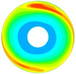
To study the liquid velocity distribution in the pump cavity of a centrifugal pump with front inducer, under the three flow conditions of 0.8Qd, 1.0Qd, 1.2Qd, the axial direction of the impeller wall surface in the centrifugal pump cavity to the rear pump-cover wall was examined. Sections of the liquid velocity distribution at the center, revealing the liquid velocity distribution in the cavity, are shown in Fig. 14.
Fig. 14 shows that at a given flow rate, fluid in the pump cavity flows along the radial and circular directions, which is an extremely complex flow where it is difficult to find regularity, let alone axisymmetry. When the flow rate increases from 0.8Qd to 1.2Qd, the area occupied by the relatively high-speed zone with a speed greater than 11.52 m/s first decreases and then increases. The area occupied by the relatively low-speed zone with a speed less than 3.84 m/s decreases, but the area of the low-speed zone is always smaller than that of the high-speed zone. This is mainly because when the volute cross-sectional area is constantly changing with angle, the liquid flow in the body cavity in the volute, coupled with the impeller cover and together with the wheel rotation valley cavity, cannot form a stable liquid flow along the radial and circumferential directions. A cavity is caused by the liquid velocity distribution, and the greater the flow rate, the larger this cavity will be.
Fig. 14Pump cavity axial center section velocity distribution

a) 0.8Qd

b) 1.0Qd

c) 1.2Qd
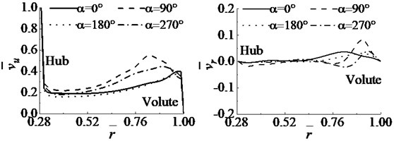
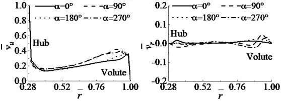
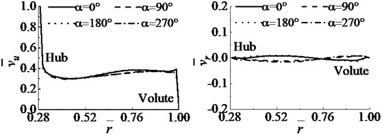
Fig. 12 and 13 show that the fluid flow velocity in the pump cavity still has a full flow boundary layer near the outer wall of the rear cover of the closely rotating impeller and the inner wall of the fixed pump cover and that there is a core flow region with little change along the axial direction between the two boundary layers. The core flow area is the main flow area of liquid in the pump cavity, accounting for more than two-thirds of its axial distance, which reflects the flow of liquid in the pump cavity as a whole. Fig. 15 shows the radial distribution curve of the liquid’s dimensionless circumference and radial velocity at the axial center ˉs= 0.5 in the pump cavity. This made it possible to study the radial distribution of the overall velocity in the pump cavity.
Fig. 15Dimensionless velocity component distribution along the radial direction
a) 0.8Qd
b) 1.0Qd
c) 1.2Qd
Fig. 15 shows that under the same flow conditions, the dimensionless circumferential velocity along the four angles (0°, 90°, 180°, and 270°) on the radial distribution of the pump cavity is 1 at the hub due to wheel rotation. Near the hub, due to liquid flow in the volute restriction region, the function value achieves a rough consensus, but not with axial symmetry, and the dimensionless circumferential velocity component angle is always greater than or equal to 0° at the 90°, 180°, and 270° angles. The radial distributions of the four angles (0°, 90°, 180°, and 270°) are different, and the radial velocity at the hub is 0. Comparing 0° with 180° and 90° with 270°, the range of dimensionless circumferential component velocity along the radial direction is larger, but the range of dimensionless radial component velocity along the radial direction is smaller. When the flow increases from 0.8Qd to 1.2Qd, the values for all four angles increase. The differences in the radial dimensionless circumferential velocity near the volute grow smaller at 0° and 180° near the hub (except for the hub wall surface) and speeds first decrease and then increase, but at 0° and 180° near the volute, speeds remain almost unchanged. At 90°, the speed in the radial direction of the pump cavity increases from the hub to the volute and decreases near the volute. At 270°, speed decreases near the volute. The dimensionless radial partial velocity shows only slight changes at 0° and 180°; especially at 0°, angular velocity remains basically unchanged, but at 90° and 270°, angular velocities are close to 0. This shows that the above analysis is consistent with the mainstream liquid velocities and flow directions in Figs. 13 and 14, which more intuitively reflect the relationship between the liquid velocity components in the pump cavity and the impeller rotation speed at different angles and radii.
4. Pump cavity pressure and axial force characteristics
4.1. Pump cavity pressure distribution
Because the liquid pressure in the pump cavity remains unchanged along the axial direction [20], to clearly analyze the pump-cavity pressure distribution law, this study examined the pump under the three working conditions (0.8Qd, 1.0Qd, and 1.2Qd). Fig. 16 shows the pressure profiles of the central section of the cavity from left to right.
Fig. 16Pressure map in the pump cavity


a) 0.8Qd

b) 1.0Qd

c) 1.2Qd
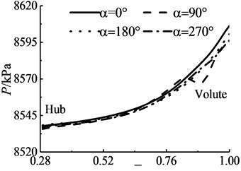
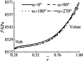
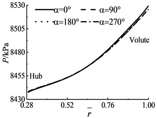
The pressure cloud diagram in Fig. 16 shows that when the flow rate is increased from 0.8Qd to 1.2Qd, the overall liquid pressure in the pump cavity is reduced, and the liquid pressure in the pump cavity varies greatly with flow rate. The liquid pressure in the pump cavity was found to change in the radial and circumferential directions at a given flow rate. Therefore, to further clarify the circumferential and radial distributions of liquid pressure in the pump cavity, three flow conditions were selected, and the liquid at the axial center of the pump cavity was chosen to be at 0°, 90°, 180°, or 270°. Fig. 17 shows the results plotted as a radial pressure distribution.
Fig. 17 shows that when the flow rate increases from 0.8Qd to 1.2Qd, the radial value of liquid pressure in the pump cavity decreases at the same angle, and the pressure distribution difference between the four angles decreases, gradually approaching a curve. Under the same flow condition, the liquid pressure in the pump cavity increases gradually along the radial direction from the hub to the volute at 0°, 270°, 90°, and 180°. For all four angles, the radial pressure difference between the volute and the hub is almost the same, but the kinetic energy of the liquid at 90° is high, and the range of the circumferential velocity of the liquid flow is larger. The range of flow peripheral velocity is small, especially near the hub. At 0.8Qd and 1.0Qd, the 90° pressure is low, the pressure potential energy is low, the kinetic energy is high, and the range of the partial velocity of the liquid in the pump cavity is high. At 0° and 180°, the radial pressure from the volute to the wheel is higher, the potential energy of the pressure is higher, and the radial velocity of the liquid in the pump cavity is higher. At 1.2Qd, the circumferential velocity of the liquid in the four angular weak cavities is almost the same, and therefore the pressure is almost the same. This occurs because from the four points of view, the volute cross-sectional area changes, and the liquid flow in the pump cavity in the volute has a restrictive effect. The 90° direction volute cross-sectional area, though small, lies close to the volute tongue position, and with the restricting effect that every tongue has on liquid flow, leads to a wider pressure difference and has a serious influence on the pump cavity 90° radial fluid flow pattern and pressure distribution. When the flow condition changes, the radial distribution of liquid pressure in the pump cavity along different angles is relatively complex, and its change is directly related to the volute section area, disc friction loss, impeller rotation speed, and other factors. However, when the flow rate increases, the influence of these factors is almost zero and can be approximately ignored.
Fig. 17Radial distribution of pump cavity pressure
a) 0.8Qd
b) 1.0Qd
c) 1.2Qd
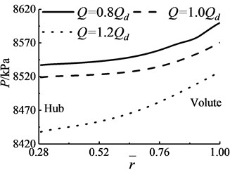
The following discussion addresses the average liquid pressure in the pump cavity at 0°, 90°, 180°, and 270° at a given radius under the three flow conditions. Fig. 18 shows the radial mean pressure variation curve.
Fig. 18 shows that under the three flow conditions (0.8Qd, 1.0Qd, and 1.2Qd), the mean pressure increases for a given radius, and the pressure difference increases. The larger the flow, the smaller is the pressure difference between the pump inlet and outlet and the lower is the head, resulting in lower pressure in the pump cavity. Under a given flow condition, the average pump cavity pressure increases slowly from hub to volute. Comparing Figs. 18 and 19, it can be seen that under the three flow conditions, the changes in the average pump cavity pressure and the 180° pressure are very similar. Under the three flow conditions of 0.8Qd, 1.0Qd, and 1.2Qd, the relative differences between the pressures are 15 kPa, 80 kPa, and 95 kPa respectively. This indicates that the mean pressure at the radial geometric center of the pump cavity is closest to the 180° pressure.
Fig. 18Mean pressure along the radial curve
4.2. Calculation of axial force in the pump cavity
After the above analysis, the axial force generated by the liquid pressure in the pump cavity area of the centrifugal pump can be approximated by two methods under the same flow condition, shown here as Eqs. (7) and (8).
Method one:
Method two:
where R1 is the hub radius (m), ˉp1 is the mean pressure (Pa) at the inner diameter of the pump cavity, ˉp2 is the mean pressure (Pa) at the outer diameter of the pump cavity, and p3 is the pressure (Pa) at the radial geometric center of the pump cavity along the 180° angle.
Table 2 shows a comparison between the calculated values of the axial forces F1 and F2 and the numerically calculated value F.
Table 2Comparison of axial force simulation results
Solution method | Flow condition | ||
0.8Qd | 1.0Qd | 1.2Qd | |
F/N | 413076 | 411930 | 409163 |
F1/N | 413577 | 412428 | 409441 |
F2/N | 412568 | 411528 | 408438 |
Table 2 shows that the calculation results of the two formulas are basically similar to the numerical calculation results. Under the condition of 0.8Qd-1.2Qd, the calculated result F1 of Eq. (5) is always greater than the numerical calculation result F, with relative errors of –0.12 %, –0.12 %, and –0.06 %. The calculated result of Eq. (6) is always smaller than the numerical calculation result F, and the relative errors between the F2 calculated by Eq. (6) and the numerical calculation result F are –0.12 %, 0.10 %, and 0.18 %. It is feasible to calculate the axial force by using the pump cavity area mean pressure or the pressure at the radial geometric center at 180°. The pump cavity mean pressure or the angular distribution of the pressure along the 180° angle can be shown as a whole. The pump cavity pressure is distributed radially. This provides an important guiding direction for correcting the axial force calculation formula for the centrifugal pump and provides a more convenient method for testing and measuring the axial force in the pump cavity.
4.3. Centrifugal pump axial force calculation
Through the numerical analysis described above, considering the liquid velocity distribution, the pressure distribution in the pump cavity, and the centrifugal pump structure with front inducer, it can be concluded that the axial force of the semi-open centrifugal impeller is composed of the cover force T1, the dynamic reaction force T2, and the axial force T3 caused by the hub structure and other factors.
(1) Cover force T1.
Compared with the closed-impeller centrifugal pump, because there is only one rear cover plate and no front cover plate in the semi-open impeller centrifugal pump, the pressure difference between the two sides of the centrifugal impeller is difficult to balance. This means that the cover force of the semi-open impeller is more affected by T1.
(2) Dynamic reaction force T2.
In the centrifugal pump, the liquid enters the impeller along the axial direction and flows out from the radial outlet. As the flow direction of the liquid changes, the impeller will experience a force that moves to the pump back cover; this force is the dynamic reaction force T2:
where ρ is the liquid density (kg/m3) and vm0 is the impeller inlet axial velocity (m/s).
(3) Axial force T3 caused by hub structure and other factors.
The inducer takes the form of equal-pitch axial flow in the centrifugal pump with front inducer as studied in this paper, and therefore the axial force caused by the structural factors of the hub is T3.
(4) Total axial force T.
The direction of the impeller inlet is positive, and the total axial force is:
Table 3 shows the numerical calculation results for each axial force and the total axial force.
Table 3Comparison of axial force simulation results for the centrifugal pump
Calculation result | Flow condition | ||
0.8Qd | 1.0Qd | 1.2Qd | |
T1/N | 69956 | 69616 | 68040 |
T2/N | –18687.2 | –18957.9 | –19456.5 |
T3/N | –36121.1 | –36118.5 | –36114.7 |
T/N | 15147.7 | 14539.6 | 12468.3 |
Table 3 shows that in the semi-open impeller centrifugal pump, the impeller cover force T1 still plays a leading role in the axial force of the centrifugal pump at a given flow rate. When the flow rate is increased from 0.8Qd to 1.2Qd, the cover force T1 is reduced. Because the flow rate and the speed at the impeller inlet are increased, the dynamic reaction force T2 is increased, and the axial direction moves towards the pump back cover. Axial force T3, which is caused by hub structure and other factors, points to the direction of the impeller inlet. Changes in these partial forces cause the total axial force T to be larger and the axial force to be smaller. Comparing these results with those in Table 1, it can be seen that the axial force of the pump cavity area and the axial force of the centrifugal pump are relatively close for all three levels of axial flow rate, further indicating that the axial force in the pump cavity is the main cause of the axial force of the centrifugal pump.
5. Conclusions
In this study, a detailed analysis of the flow mechanism and axial force characteristics of the pump cavity of a centrifugal pump with front inducer has been carried out, and the following conclusions were obtained:
1) At the same flow rate operating point, the velocity of liquid in the pump cavity of the centrifugal pump is distributed along the circumferential and radial directions, with no axial symmetry. The lower the flow rate, the larger the cross-sectional area of the volute becomes, and the higher is the intra-cavity velocity at corresponding angles. In the volute, the mainstream flow plays a major role in restricting liquid flow in the pump cavity at different angles.
2) At the same angle, as the flow rate increases, the flow direction of the eddy current generated by the main fluid in the pump cavity remains the same. However, if the flow rate is too large, the flow direction of this eddy current generated by the main fluid in the pump cavity will change. The vortex flow direction is consistent at 0° and 180° angles it is also consistent at 90° and 270° angles.
3) When the flow increases, the axial center circumferential partial velocity curve of the pump cavity of the centrifugal pump with front inducer approaches a straight line and the speed approaches a fixed value. The difference between the axial center circumferential partial velocity of the pump cavity of the centrifugal pump with front inducer and the average rotational speed of the impeller cover in the pump cavity area is reduced. The pressure range in the pump cavity is reduced, and the liquid pressure in the pump cavity increases at the same angle in the radial direction.
References
-
Badr H. M., Ahmed W. H. Pumping Machinery Theory and Practice. West Sussex, John Wiley and Sons Ltd, 2015.
-
Borghi M., Zardin B. Axial balance of external gear pumps and motors: modelling and discussing the influence of elastohydrodynamic lubrication in the axial gap. Proceedings of the ASME International Mechanical Engineering Congress and Exposition, Houston, 2015.
-
Bruurs K. A. J., van Esch B. P. M., van der Schoot M. S., et al. Axial thrust prediction for a multi-stage centrifugal pump. Fluids Engineering Division Summer Meeting, 2017.
-
Dautherty R. L. Centrifugal Pump. Mc Graw-Hill Book Co., New York, 1915.
-
Debuchy R., Nour F. A., Bois G. An analytical modeling of the central core flow in a rotor-stator system with several Preswirl conditions. Journal of Fluids Engineering, Vol. 132, Issue 6, 2010, p. 61102.
-
Dong W., Chu W. L. Numerical investigation of fluid flow mechanism in the back shroud cavity of a centrifugal pump. Journal of Applied Fluid Mechanics, Vol. 11, Issue 3, 2018, p. 709-719.
-
George S., Eric O. Experimental eva1uation of axial thrust in pumps. World Pumps, Vol. 393, Issue 1999, 1999, p. 34-37.
-
Godbole V., Patil R., Gavade S. S. Axial thrust in centrifugal pumps-experimental analysis. 15th International Conference on Experimental Mechanics, Porto, Portugal, 2012.
-
Guo M., Liu S. H., Tang X. L., et al. Evaluation of shaft forces in a vertical canned motor through local hydraulic loss analysis. Advances in Mechanical Engineering, Vol. 3, Issue 10, 2018, https://doi.org/10.1177/1687814018765599.
-
Guo X. M., Zhu Z. C., Shi G. P., et al. Effects of rotational speeds on the performance of a centrifugal pump with a variable-pitch inducer. Journal of Hydrodynamics, Vol. 29, Issue 5, 2017, p. 854-862.
-
Hong S. S., Kim D. J., Kim J. S., et al. Study on inducer and impeller of a centrifugal pump for a rocket engine turbopump. Proceedings of the Institution of Mechanical Engineers Part C-Journal of Mechanical Engineering Science, Vol. 227, Issue 2, 2013, p. 311-319.
-
Jafarzadeh B., Mokhtarpoor R., Alishahl M. M., et al. Investigation of turbulence modeling in a high speed centrifugal pump with an inducer. International Mechanical Engineering Congress and Exposition, 2009.
-
Lobanoff V. S., Ross R. R. Centrifugal Pumps: Design and Application. 2nd ed., Houston, Gulf Professional Publishing, 2013.
-
Matsui J., Mugiyama T. Effect of J-Groove on the axial thrust in centrifugal pump. 10th Asian International Conference on Fluid Machinery, Kuala Lumpur, Malaysia, 2010.
-
Nishida M., Nakayama K., Sakota D., et al. Properties of a monopivot centrifugal blood pump manufactured by 3D printing. Journal of Artificial Organs, Vol. 19, Issue 4, 2016, p. 322-329.
-
Salvadori S., Marini A., Martelli F. Methodology for the residual axial thrust evaluation in multistage centrifugal pumps. Engineering Applications of Computational Fluid Mechanics, Vol. 6, Issue 2, 2012, p. 271-284.
-
Siddique M. H., Samad A., Husain A. Combined effects of viscosity and surface roughness on electric submersible pump performance. Proceedings of the Institution of Mechanical Engineers Part A-Journal of Power and Energy, Vol. 341, Issue 4, 2017, p. 303-316.
-
Wang C., Shi W. D., Zhang L. Calculation formula optimization and effect of ring clearance on axial force of multistage pump. Mathematical Problems in Engineering, Vol. 2013, 2013, p. 749375.
-
Ye X. Y., Hu J. N., Wang J., et al. Numerical and experimental investigation of performance and reliability in new reverse osmosis seawater desalination high pressure pump. International Mechanical Engineering Congress and Exposition, 2014.
-
Zhou L., Shi W. D., Li W., et al. Numerical and experimental study of axial force and hydraulic performance in a deep-well centrifugal pump with different impeller rear shroud radius. Journal of Fluids Engineering, Vol. 135, Issue 10, 2013, p. 104501.
Cited by
About this article
This work was supported by the scientific research foundation of Basic Natural Science Research Program of Shaanxi Province (2019JLM-58), Fundamental Research Funds for the Central Universities (No. Z1090219041), and Sci-ence and Technology Plan Project Funds for Shaanxi Provincial Department of Water Resources (2019slkj-15).

