Abstract
This work deal with the biomechanical analysis of the Captum Collum Diaphysis (CCD) femur bone. The femur is the largest bone in the upper leg. The angle between femur neck and femur shaft of the femora is a parameter in determining the CCD or FSA angle. 126 ° is the usual angle for a healthy adult and variation in this angle leads to the CCD. This angle in the femur bone helps in determining the knock knee and bow leggedness orthopaedic disease. This angle impacts on the distribution of stress and deflection in the femur bone during the daily activities. Computational Multi-Scale analysis has been done for homogenized properties of femur bone. A Numerical simulation has been made for the biomechanical analysis of CCD femur bone using Finite Element Method. There is significant impact of stress distribution and deflection over the femur bone in case of change in optimum CCD angle (coxa norma) and also leads to change the natural frequency of the bone. Predicted results shows the above mentioned disease behaviour over the healthy bone. The study of these deformity and their results are of clinical importance in musculoseketal behaviour of the human femur bone.
1. Introduction
The femur is the longest, voluminous and strongest bone in the human body. The Fig. 1 shows various parts of femur bone and presents the most important terms and definitions [1]. The femur is divided in three main parts. The upper extremity consists of a rounded head which contacted with the acetabulum of the hip bone to form the hip joint having narrow neck with two protuberances for muscle connection known as the greater and lesser trochanter. The body or shaft (corpus femoris) is cylindrical with upper part is slightly broader above than lower and is curve in geometry with front is convex and behind to be concave. The lower extremity (distal extremity) is more prominent in length compared to the upper extremity with two oblong eminences known as the condyles as shown in Fig. 1.
Fig. 1Ventral and dorsal view of femur bone
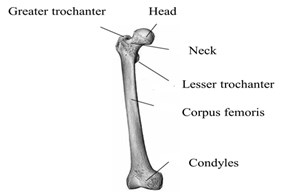
Fig. 2Structure of femur
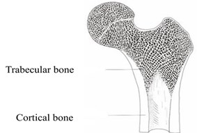
Fig. 2 describes the two main kinds of bone structure of the femur, the spongy trabecular bone and compact cortical bone: The outside part of the shaft of the femur consists of compact bone and forms the outer cover for all bones of the body. Trabecular bone is for providing support strength at the two ends of the weight-bearing bone and found at the extremes heads of long bones.
The hip joint of the femur is filled with a micro-fine small strut of spongiosa bone. This fine framework near the joint is the function of this structure is to distribute the load and to act as a shock absorber or dash pot. Bone marrow is yet another essential material present in the bone behaving like the spongy tissue carries red blood cells and white blood cells. During standing on one leg, the neck of the femur has to transmit about 2.5 to 6 times the body weight (BW) as axial loading due to lever relationships. To withstand this high load, a well-adapted design and structure has to exist. The cortical bone has a higher density and stiffness than the spongiosa bone and is therefore, better adapted to higher local stresses compare to trabecular bone [2]. Now a day’s a prevalent orthopaedic disease is found in the human based on the femur shaft angle (FSA). The angle between the neck and shaft of the femur is known as FSA or CCD (Caput Collum-Diaphysis) angle. CCD usually measures approximately 126° in adults (coxa norma). An abnormally small angle between femur shaft and neck is known as coxa vara generally ranges in between 100° to 120° and larger angle than this known to be as coxa valga generally ranges 130° to 160° (Fig. 3). This angle changes in shape of the femur naturally affect the knee, coxa valga may lead to the problem of genu varum (bow-leggedness), while coxa vara creates to the genu valgum (knock-knees) deformity [3]. Bowlegs is a problem associated with larger angle in which human legs appear bowed out; it means that the knees stay wider apart even when the ankles are together. Bowlegs is an indication of a disease, like a Blount’s disease or rickets, and leads to arthritis in the knees and hips [3-5]. Treatment options include braces, casts, or surgery to correct these bone abnormalities. Knock knee is a type of deformity. A human affected with this type of deformity has a large gap between their feet when they are standing with their knees together. Knock knees is a condition that needs treatment, especially if the condition develops in older children or adults, or doesn’t improve with age. Genu valgum (knock knee) is the condition where the femurs took the positions in which the knees touch one another. Another deformity is of opposite extreme is known as Genu varum (bow-leggedness). In this work we considered 146° for coxa valga and 106°for caxa vara deformity in the femur bone compare to 126° for coxa norma.
Fig. 3Caput collum diaphysis deformity based on FSA [3]
![Caput collum diaphysis deformity based on FSA [3]](https://static-01.extrica.com/articles/21133/21133-img3.jpg)
a) Coxa Norma
![Caput collum diaphysis deformity based on FSA [3]](https://static-01.extrica.com/articles/21133/21133-img4.jpg)
b) Coxa Vara
![Caput collum diaphysis deformity based on FSA [3]](https://static-01.extrica.com/articles/21133/21133-img5.jpg)
c) Coxa Valga
2. Materials and methods
The generated model is of an ideal femur bone of an age of 27 years old individual healthy human whose weight is 75 kg which was recreated from DICOM images and is imported in the Ansys Design Modeller. Geometry for caput collum diaphysis was modeled in the space claim resembling the same that of actual deformity in the femur bone. Fig. 4 shows the flow chart for the analysis of the work carried out for this research work.2D femur bone modeled from the ideal femur bone model obtained from DICOM Images in ANSYS SpaceClaim as of same mass moment of inertia that of the actual model in ANSYS for carrying the analysis of different CCD femur bone. An optimized Meshing required for Finite Element Analysis of the femur model and developed in ANSYS Workbench, a proper setting has been executed in order to use smaller and finer elements based on the relevance, smoothing proximities and curvatures for the model. The model is meshed using 9015 tetrahedral elements. The material properties are assigned for different portions of femur bone, Table 1 provides the parameters used to model the femur model.
Fig. 4The numerical procedure followed to model CCD’s
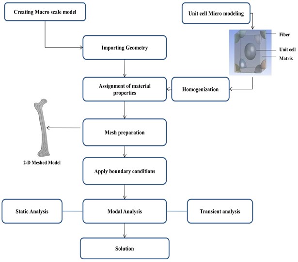
Table 1Material properties of different portions of femur bone [5]
Parameter | Cortical bone | Trabecular bone | Bone marrow |
Hounsfield unit (HU) | 2200 | 800 | 660 |
Density (g/cm3) | 2.0208 | 1.3712 | 1.012 |
Young’s modulus (MPa) | 15550 | 2029.4 | 880 |
Poisson’s ratio | 0.4 | 0.4 | 0.3 |
For the present work Homogenization has been done using Computational Multiscale Analysis System (CMAS) in ANSYS to get the homogenized material properties of the bone. The creation of a micro-scaled model of femur bone has been done in ANSYS design modeler using CMAS. For this unidirectional centered and corner cortical bone and Trabecular bone structure surrounded by the bone marrow matrix is chosen and assignment of the material properties to the individual elements followed by meshing of the micro model. Required homogenized properties were evaluated after solving the meshed models are shown in Table 2.
Table 2Homogenized properties for femur bone
Homogenized properties | Density(g/cm3) | Young’s modulus (MPa) | Poisson’s ratio |
Femur bone | 2.02 | 8950 | 0.36 |
The boundary condition for the femur bone model is an important task in FEA, fixed boundary condition has been applied on the distal end (condyles) of the femur and the hip contact force has been applied on the head of the femur in order to calculate the normal stresses in the first stance of walking [13].
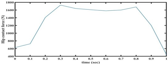
Static structural analysis is carried out to evaluate the Stresses induced in the femur bone. In this analysis, we need to measure the hip contact force that applied on the head of the femur during normal activities like standing. Considering the typical weight of 75 kg, a hip contact force of 627 N is applied at the hip contact region in femur head and distal end of femur bone is fixed. Modal analysis was carried out to evaluate the natural frequencies and corresponding mode shapes. The transient analysis carried out corresponding to one gait cycle of walking (Fig. 5) [17] for all the cases of the deformity.
Fig. 5Hipcontact force vs time during walking
3. Results and discussion
3.1. Static results for the bone with various FSA angle
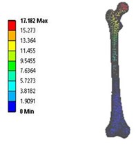
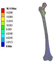
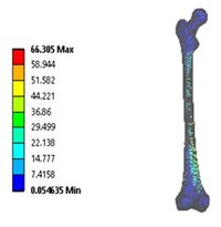
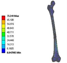
Static analysis has been carried out on both 2D and 3D model of the femur bone with different FSA to evaluate the von mises stresses induced in the human femur bone. The hip contact force is applied at the head , while the distal end is fixed .The maximum stress for CCD angle 106° is 66.305 MPa while the maximum deflection is 17.182 mm and for the CCD angle 146° maximum stress is 73.241 MPa which occurred at the neck and shaft region of the femur bone with the maximum deflection of 18.11 mm. As the angle direction for the femur shaft and head of femur are aligned in different direction, so the deflection is leading opposite in direction to each other for both the cases. From the Data source it shows that the permissible deformation for the normal femur bone is in the range as mention in the literature [5].
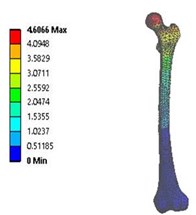
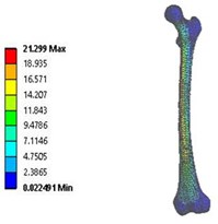
Fig. 6Total deformation in: a) coxa valga, b) coxa norma, c) coxa vara in 3D model static analysis
a)
b)
c)
Fig. 7Vonmises stress distribution: a) coxa valga, b) coxa norma, c) coxa vara in 3D model static analysis
a)
b)
c)
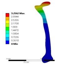
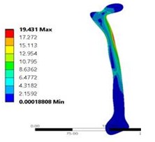
Fig. 8a) Total deformation in coxa norma, and b) vonmises stress distribution coxa norma in 2D model static analysis
a)
b)
From Figure 6 and 7 total deformation and stress induced are nominal and are in the acceptable range [13] for the coxa norma bone. While there is increase in the deformation and stress distribution for the coxa valga and coxa vara deformed bone. For both condition, deformation is more and are in opposite direction which may lead the bones to move closer and apart during standing and walking creates the condition of the knock knee and bow leggedness while from Fig. 8 shows the result for 2D model static analysis for coxa norma in which deformation of 3.256 mm and maximum stress of 19.431 MPa and the pattern of stress distribution is almost same as 3D model shown in Fig. 6. Evaluated values of total deformation and stress are shown in Table 3.
Table 3Variation in total deformation and stress with different FSA
Bone | Coxa valga 3D model | Coxa valga 2D model | Coxa norma 3D model | Coxa norma 2D model | Coxa vara 3D model | Coxa vara 2D model |
FSA angle (degrees) | 146° | 146° | 126° | 126° | 106° | 106° |
Deformation (mm) | 18.110 | 19.431 | 4.606 | 3.256 | 17.182 | 15.706 |
Stress (MPa) | 73.241 | 71.202 | 21.299 | 19.431 | 66.305 | 64.201 |
Frequency (Hz) | 4120 | 4208 | 1986 | 1920 | 3980 | 3902 |
3.2. Modal results for the bone with various FSA angle
Further a modal analysis has been conducted for the estimation of the natural frequencies for femur bone with three distinct cases of deformity. The analysis predicted the natural frequencies of the bone in order to avoid the resonance condition during any daily activity. Table 3 having natural frequencies values for different deformities. Results predict the change in the natural frequency of the femur bone with the different FSA angle as the mass and stiffness changes for it. the variation in the frequencies for the coxa valga and coxa vara conditions compare to the coxa norma shown in Table 3.
3.3. Transient analysis for the bone with various FSA angle
The transient analysis was also conducted on the bone to study the behavior of the bone under forces as a function of time.
Fig. 9Stress distribution across the CCD Femur bone
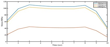
Fig. 10Total deformation across the CCD Femur bone
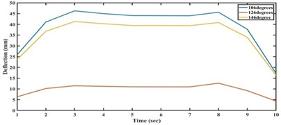
Fig. 9 and Fig. 10 shows the stress distribution and deformation within the bone. Values are small for the coxa norma compared to coxa valga and coxa vara. These two deformities cause an increase in the stress and deflection level with the function of time. The neck and shaft portion of the bone shows the severity in stress and deflection distribution.
4. Conclusions
In this work we make a comprehensive model of human femur bone to study the static and dynamic properties, it was noticed that stresses induced in CCD’s (coxa vara and coxa valga). Static and dynamic deformation of bone is also be more significant during deformities. These results will aid the tests related to strength, fixation and friction of implants and also important for surgeon in femur surgeries and bone prosthesis. An increase in the angle may lead to the bowing of legs knee, while a decrease in angle leads to the increase in the stress and deformation and having the tendency of knocking knee.
References
-
Raji Nareliya, Veerendra Kumar Biomechanical analysis of human femur bone. International Journal of Engineering Science and Technology (IJEST), Vol. 3, Issue 4, 2011, p. 3090-3094.
-
Peng L., Bai J., Zeng X., Zhou Y. Comparison of isotropic and orthotropic material property assignments on femoral finite element models under two loading conditions. Medical Engineering Physics, Vol. 28, Issue 3, 2006, p. 227-233.
-
Wikimedia Commons Category: Anatomy, http://www.commons.wikimedia.org/wiki/Anatomy.
-
Wagner David W., Kaan Divringi, Can Ozcan, Grujicic M., Pandurangan B., Grujicic A. Combined musculoskeletal dynamics/structural finite element analysis of femur physiological loads during walking. Multidiscipline Modeling in Materials and Structures, Vol. 6, Issue 4, 2010, p. 417-443.
-
Yousif Albert E., Mustafa Aziz Y. Biomechanical Analysis of the human femur bone during going upstairs and sitting down. 1st National Conference for Engineering Sciences, 2012.
-
Mc Namara B. P., Cristofolini L., Toni, Taylor D. Relationship between bone-prosthesis bonding and load transfer in total hip reconstruction. Journal of Biomechanics, Vol. 30, Issue 6, 1997, p. 621-630.
-
Hernandez C., Keaveny T. A biomechanical perspective on bone quality. Bone, Vol. 39, Issue 6, 2006, p. 1173-1181.
-
Frost H. Why do bone strength and mass in aging adults become unresponsive to vigorous exercise? Journal of Bone and Mineral Metabolism, Vol. 17, Issue 2, 1999, p. 90-97.
-
Lee B. H., Kim J. K., Kim Y. D., Choi K., Lee K. H. In vivo behavior and mechanical stability of surfacemodified titanium implants by plasma spray coating and chemical treatments. Journal of Biomedical Materials Research Part A, Vol. 69, Issue 2, 2004, p. 279-285.
-
Doblare M., Garcia J. M. On the modelling bone tissue fracture and healing of the bone tissue. Acta Cient Venez, Vol. 54, Issue 1, 2003, p. 58-75.
-
Kourtis L. C., Carter D. R., Kesari H., Beaupre G. S. A new software tool (VA-BATTS) to calculate bending, axial, torsional and transverse shear stresses within bone cross section having inhomogeneous material properties. Computer Methods in Biomechanics and Biomedical Engineering, Vol. 11, Issue 5, 2008, p. 463-476.
-
Baca V., Horak Z., Mikulenka P., Dzupa V. Comparison of an inhomogeneous orthotropic and isotropic material models used for FE analyses. Medical Engineering and Physics, Vol. 30, Issue 7, 2008, p. 924-930.
-
Seo Jeong-Woo, Kang Dong-Won, Kim Ju-Young, Yang Seung-Tae, Kim Dae-Hyeok, Choi Jin-Seung, Tack Gye-Rae a Finite element analysis of the femur during stance phase of gait based on musculoskeletal model simulation. Bio-Medical Materials and Engineering, Vol. 24, 2014, p. 2485-2493.
-
ANSYS Workbench User Guide. ANSYS, Inc., 2009.
-
Bergmann G., Graichen F., Siraky J., Jendrzynski H., Rohlmann A. Multichannel strain gauge telemetry for orthopaedic implants. Journal of Biomechanics, Vol. 21, 1988, p. 169-176.
-
Graichen F., Bergmann G. Four-channel telemetry system for in vivo measurement of hip joint forces. Journal of Biomedical Engineering, Vol. 13, 1991, p. 370-374.
-
Bergmann G., Graichen F., Rohlmann A. Hip joint forces during walking and running, measured in two patients. Journal of Biomechanics, Vol. 26, 1993, p. 969-990.
-
Karpiński Robert, Jaworski Łukasz, Czubacka Paulina The structural and mechanical properties of the bone. Journal of Technology and Exploitation in Mechanical Engineering, Vol. 3, Issue 1, 2017, p. 43-50.
-
Graichen F., Bergmann G., Rohlmann A. Hip endoprosthesis for in vivo measurement of joint force and temperature. Journal of Biomechanics, Vol. 32, 1999, p. 1113-1117.
-
Bergmann G., Deuretzbacher G., Heller M., Graichen F., Rohlmann A., Strauss J., Duda G. N. Hip contact forces and gait patterns from routine activities. Journal of Biomechanics, Vol. 34, 2001, p. 859-871.
-
Bergmann G., Graichen F., Rohlmann A. “HIP98” Biomechanics Lab. Benjamin Franklin School of Medicine, Free University of Berlin, Gemany, 2001.
-
Bergmann G., Graichen F., Rohlmann A., Bender A., Heinlein B., Duda Gn, Heller Mo, Morlock M. M. Realistic loads for testing hip implants. Bio-Medical Materials and Engineering, Vol. 20, Issue 2, 2010, p. 65-75.
-
Wang Xishi, Wang Tian-Ying, Jiang Fuchuan, Duan Yixiang The hip stress level analysis for human routine activities. Bio-Medical Materials and Engineering, Vol. 17, 2005, p. 153-158.
-
Arun K. V., Jadhav Kunal K. Behaviour of human femur bone under bending and impact loads. European Journal of Clinical and Biomedical Sciences, Vol. 2, Issue 2, 2016, p. 6-13.

