Abstract
A 12-degree-of-freedom (DOF) spur gear dynamic model is constructed, which is coupled by the mesh gear pair and the gearbox. The construction method of spur gear coupling dynamic model, based on lumped mass method, is better than finite element method, due to higher modeling efficiency. The work would be benefit to spur gear coupling dynamic modeling and analyses.
Highlights
- A dynamic model coupled by the mesh gear pair and the gearbox is constructed.
- The construction method of spur gear coupling dynamic model is more efficient.
- Using modal assurance criterion to verify the accuracy of the proposed method.
1. Introduction
Gear dynamic models are focused by many scholars. There is an extensive body of literatures on it [1-9]. Jin et al. established gear dynamic models coupled with bending-torsion-axis-swing of mesh pairs based on lumped mass method [10]. Zhu et al. constructed finite element models of the gear transmission, and evaluated dynamic behavior of the system [11, 12]. Ren et al. proposed a construction method of gear dynamic models based on substructure method [13-15]. However, the gear coupling dynamic models associated with mesh pairs and gearbox supports are few studied. Thus, in the paper, a 12 DOFs spur gear coupling dynamic model, based on lumped mass method, is proposed. The work would be helpful to the spur gear coupling dynamic analyses.
2. Construction of 12DOFs dynamic model
The gear transmission system is mainly composed of two spur gears, bearings and gearbox supports. When modeling with the finite element method, it is inefficient because of the complexity of the gearbox supports. Therefore, a 12 DOFs coupling dynamic model based on lumped mass method is established, as shown in Fig. 1.
Fig. 1The coupling dynamic model
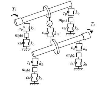
As illustrated in Fig. 1, subscript and express driving gear and driven gear, respectively, is a bending stiffness, is a bending damping, is a mesh stiffness, is a mesh damping, is a static transmission errors (STE), is the input torsion, is the output torsion, is the support stiffness, is the support damping. Moreover, , , and are the equivalent masses of the gearbox supports.
As given in Fig. 1, the mathematical equations of the meshing pair could be derived by:
where subscript and express motor and load, respectively, is a torsion degree, is a bending degree, is a mass, is a base circle radius, is a moment of inertia, and are torsional stiffness of the shaft, and are torsional damping of the shaft, and could be deduced as:
The gearbox supports dynamic equivalent model is proposed, as shown in Fig. 2.
Fig. 2The gearbox supports dynamic equivalent model
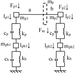
a) Equivalent model of the driving gear
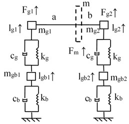
b) Equivalent model of the driven gear
As illustrated in Fig. 2, the equivalent mass of the gears at the bearing fulcrum could be deduced as:
where and are the distance from the gear to the bearing fulcrum.
As given in Fig. 2, the mathematical equations of the support structure could be derived by:
According to the deformation coordination relationship, as shown in Fig. 3, the deformation coordination equations could be derived by:
Fig. 3The coordination relationship
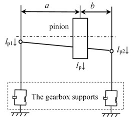
According to the deformation coordination Eq. (5), Eq. (1) and Eq. (4), a 12 DOFs coupling dynamic model, based on lumped mass method, is established.
3. Simulations
In order to verify the accuracy of the proposed method, the parameters of an example case are listed in Table 1.
Table 1Parameters of system
Symbol name | Value | Unit |
Modulus / | 4 | mm |
Pressure angle / | 20 | ° |
Tooth number of driving gear / | 23 | – |
Tooth number of driven gear / | 69 | – |
Addendum coefficient / | 1 | – |
Clearance coefficient / | 0.25 | – |
According to the 12 DOFs coupling dynamic model and the parameters listed in Table 1, the natural frequencies of the example case are simulated. Part of the results are shown in Fig. 4.
In the case of Fig. 4, the natural vibration mode vector of the first-order non-zero natural frequency (second frequency: 1403 Hz) is:
Fig. 4Natural frequency simulations
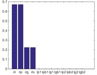
a) First frequency: 0 Hz
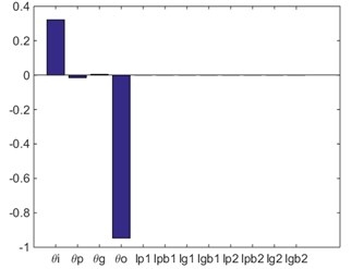
b) Second frequency: 1403 Hz
According to the simulation result based on finite element model, as shown in Fig. 5, the natural vibration mode vector could be expressed as:
Fig. 5Natural vibration mode based on FEM (natural frequency: 1282.9 Hz)
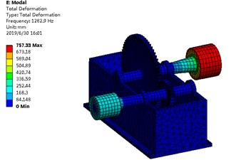
According to the modal assurance criterion (MAC), Eq. (6) and Eq. (7), the natural vibration mode vector correlation can be derived by:
According to Eq. (8), the MAC value of the example case is 0.9997, namely, the natural vibration mode shown in Fig. 4(b) and the natural vibration mode shown in Fig. 5 are the same-order physical mode. The relative error of the natural frequencies between two methods is calculated, as shown in Table 2.
Table 2The relative error of the natural frequencies between two methods
Value | Unit | |
The natural frequency based on lumped mass method | 1403 | Hz |
The natural frequency based on FEM | 1282.9 | |
The relative error | 9.36 | % |
In the case of Table 2, the relative error of the natural frequencies between two methods is 9.36 %, namely, the proposed method is accurate and feasible.
4. Conclusions
In the issue, a 12 DOFs spur gear coupling dynamic model, based on lumped mass method, is proposed. The construction method of spur gear coupling dynamic model is better than finite element method, because it enables rapid modeling of complex gearbox and makes dynamic modeling more efficient. This contribution would be helpful to the spur gear coupling dynamic modeling and analyses.
References
-
Mark W. D. Use of the generalized transmission error in the equations of motion of gear systems. Journal of Mechanical Design, Vol. 109, Issue 2, 1987, p. 283-291.
-
Şener Ö. S., Özgüven H. N. Dynamic analysis of geared shaft systems by using a continuous system model. Journal of Sound and Vibration, Vol. 166, Issue 3, 1993, p. 539-556.
-
Walha L., Louati J., Fakhfakh T., et al. Dynamic Response of Two-Stage Gear System Damaged by Teeth Defects. Oficyna Wydawnicza Politechniki Warszawskiej, 2005.
-
Bodas A., Kahraman A. Guda-1 influence of carrier and gear manufacturing errors on the static planet load sharing behavior of planetary gear sets (gear unit design and applications). The Japan Society of Mechanical Engineers, 2017, p. 633-638.
-
Li Z., Zhu R. Sensitivity predictions of geometric parameters on engagement impacts of face gear drives. Journal of Vibroengineering, Vol. 17, Issue 5, 2015, p. 2236-2246.
-
Hu Z. H., Tang J. Y., Chen S. Y., Lei D. C. Effect of mesh stiffness on the dynamic response of face gear transmission system. Journal of Mechanical Design, Vol. 135, Issue 7, 2013, p. 071005.
-
Fernandez A., Garcia P., Ibarbia A. D. Enhanced model of gear transmission dynamics for condition monitoring applications: Effects of torque, friction and bearing clearance. Mechanical Systems and Signal Processing, Vol. 85, 2017, p. 445-467.
-
Rigaud E., Sabot Effect J. Elasticity of shafts, bearings, casing and couplings on the critical rotational speeds of a gearbox. Physics, Vol. 1230, 2007, p. 833-845.
-
Shaobin L. Study on Coupled Thermo-Elastic Deformation and Nonlinear Dynamic Emulate about High-Speed, Heavy-Load Gear Transmission System. Chongqing University, 2004.
-
Jin G., Zhu R., Bao H. Nonlinear dynamical characteristics of face gear transmission system. Journal of Central South University, Vol. 5, Issue 41, 2010, p. 1807-1813.
-
Zhu C. C., Lu B., Xu X. Y., et al. Analysis of coupling characteristics of transmission system and structural system of high power marine gearbox. Journal of Ship Mechanics, Vol. 15, Issue 11, 2011, p. 1315-1321.
-
Zhu C. C., Lu B., Xu X. Y., et al. Analysis of heavy duty marine gearbox with thermal-elastic coupling. Journal of Ship Mechanics, Vol. 15, Issue 8, 2011, p. 898-905.
-
Ren Y. F., Chang S., Liu G., et al. Analysis of influence of box flexibility on dynamic characteristics of gear transmission system. Journal of Vibration and Shock, Vol. 14, 2017.
-
Liu L., Zhao C. Q., Ren Y. F., et al. Dynamic modeling and box influence analysis of gearbox fully coupled system. Journal of Harbin Engineering University, Vol. 39, Issue 3, 2018, p. 561-568.
-
He Z. X., Zhao C. Q., Ren Y. F., et al. Dynamic response analysis of planetary gear transmission system with coupling box vibration. Journal of South China University of Technology, Vol. 9, 2015, p. 128-134.
About this article
The authors are grateful for the financial support provided by the National Natural Science Foundation of China under No. 51775264, and by National Key Laboratory of Science and Technology on Helicopter Transmission (Nanjing University of Aeronautics and Astronautics) (Grant No. HTL-A-19G06). In addition, the authors declare that there is no conflict of interests regarding the publication of this article.
