Abstract
The hybrid finite element method and statistical energy method was used to study the vibro-acoustic coupling characteristics of an engineering vehicle cab. The parameters of the statistical energy method, such as modal densities, damping loss factors and coupling loss factors of substructures, were acquired by numerical and analytical methods. The acoustic-structure coupling of the cab was established based on the modal densities of substructures. The vibration and noise excitations of the cab were measured by test and the sound pressure level response of the driver’s ear was predicted. It was shown that the prediction results based on the hybrid method are in agreement with the experiments and the proposed method can be applied to predict the mid-frequency response of complex vibro-acoustic coupling systems with a moderate computational cost and accuracy.
1. Introduction
At present, the dynamic response of the structure-acoustic problem can be predicted by the deterministic or statistical methods. Deterministic methods, such as boundary element method (BEM) [1, 2] and finite element method (FEM) [3, 4], are usually applied to low-frequency range due to the prohibitive calculational cost. Statistical methods, such as statistical energy analysis (SEA) [5-8], applied to dynamic analysis from the energy point of view are limited to the high frequencies as a result of the lack of accuracy. In some cases, however, there is a mid-frequency range, in which neither deterministic methods nor statistical methods can be used here with accuracy and validity.
For the “mid-frequency problem”, the hybrid FEM-SEA had been recently proposed [9-13], which combine advantages of the two well established methods. Shorter [14] investigated the prediction of the transmission loss of a front-of-dash component based on the hybrid method and the results obtained by simulation was in good agreement with the test. Prasanth S. [15] built the hybrid model of structure-borne noise in a fully trimmed vehicle from 200 Hz to 1000 Hz. It was shown that the hybrid model could accurately predict absolute panel vibration and cavity SPL. Azevedo [16] modeled the floor structure of an aircraft using the hybrid method to predict the response of the vibration and the results was experimentally validated. Cordioli [17] investigated the transmission loss of various slits based on the hybrid FE-SEA method, and analyzed the parameters of influencing the transmission loss of the typical slits and seals.
The purpose of the present contribution was to predict the structure-acoustic response of an engineering machinery cab firstly based on the hybrid FE-SEA method in the mid-frequency range. Firstly, the theories behind the hybrid model and the governing equations of the hybrid method were presented, and then, the parameters of the hybrid model were calculated by analytical methods. Finally, the response of the cab is conducted by comparing with experiment and some conclusions are discussed.
2. Mathematical formulation
2.1. Theory of the hybrid FE-SEA method
In hybrid model, the FE part is represented by a set of degrees of freedom q, and the SEA subsystems by their average vibrational energy level E [10-12]. The relation is written in terms of the cross-spectral matrix of force Sff:
where E[·] denotes the ensemble average, Ddir is the “direct field” dynamic stiffness matrix, ω is the angular frequency and n is the modal density of the SEA subsystem. The response of the FE dofs is given in cross-spectral form by:
where Ddir(k),Ek, and nk represent “direct field” dynamic stiffness matrix, the average vibrational or sound energy level, and the modal density of the kth statistical subsystem. Sqq and Sff,d represent the cross-spectral matrices of q and f, and the dynamic stiffness matrix of the FE model Dtot can be written as:
The average energy response of the SEA subsystems, written as:
where, power input Pext(in,j) can be computed by the displacement response qd arising from external load f applied to the subsystem j and its dynamic stiffness matrix D(j)dir. ηij is the coupling loss factor.
Eq. (2) and Eq. (4) constitute primary equations of the hybrid FE-SEA method. Once, the energy response of SEA subsystem is computed by Eq. (4), the response of q is also computed by Eq. (2) eventually.
2.2. Parameters of the hybrid model
For ideal subsystems, the modal densities of which can be given by Eq. (5) and Eq. (6):
where N(f) is modes in band, f is the representation of the frequency. ω is the circular frequency. c is the sound speed. V0 is the volume of the acoustic field. As is the surface area of the acoustic cavity and lr is the total length of the edges.
DLF is a measure of the rate of energy flowing out of a subsystem through a dissipation mechanism, which is defined as follows:
where, structural loss factor (ηks) caused by internal friction of the kth subsystem is the inherent properties of materials. According to the structure loss factor-material table, ηks of tempered glass is 0.001 and ηks of steel plates range from 0.0001 to 0.0006. The loss factor of acoustic radiation (ηkr) can be acquired from the Eqn. (8) and Eqn. (9):
where ρ0 is the air mass density. c represents the sound speed. ρs, δ represent the area density and radiation ratio of the structure. Ap represents the radiation area. Pr represents the circumference of the plate. fc represents the critical frequency. λc represents the critical wavelength and β represents the boundary condition factor. (fct= 12.9 m/s with steel plate and fct= 12.6 m/s with glass plate. β= 1 with simple supported condition and β= 2 with clamped condition).
The interior acoustic cavity regarded as semi-free sound field is written as:
where ηc represents the loss factor of cavity. α represents the sound absorption coefficient, As represents the surface area of cavity. f is the center frequency, and V represents the volume of cavity.
The coupling loss factors (CLFS) are created simultaneously when the appropriate wave fields are connected. As to the point connected subsystems, the CLFs can be acquired by the Eq. (11):
whereZi+Zj is the total impedance of the point junction. ni(ω) is the model density of subsystem i and Ri, Rj is the real part of input impedance at the point junction between subsystems i, j, respectively.
The CLFs for the line junction subsystems can be defined as:
where l represents the length of coupling line, cg is the bending wave velocity of subsystem, Ai represents the surface area, and τij is the wave transmission coefficient from subsystem i to j.
For the area coupling structure, the CLFs can be defined as follows:
where ηsc, ηcs represents the DLF from structural subsystem to acoustic cavity and the reverse one, respectively. σsc represents the sound radiation coefficient from structural subsystem to acoustic cavity.
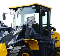
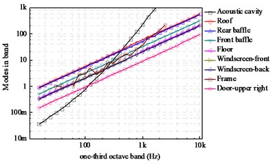
Fig. 1a) Structural-acoustic system of engineering machinery cab, b) modes per 1/3rd octave band for the principal structural subsystems
a)
b)
3. Modeling of the engineering machinery cab
3.1. Description of the structural-acoustic system
In this paper, we are interested in studying the acoustic response of an engineering machinery cab at passengers’ ears under engine’s structure-borne and air-borne excitations in middle frequency range. The cab is made of two shield panels, two windscreen panels, four door glass panels and two top and bottom panels, plotted in Fig. 1(a). The frame is of rectangular shape and made of connected steel beams with different cross sections. The cavity encloses a volume of V0= 2.63 m3 and the total surface area is As= 13.48 m2.
3.2. Modeling of the cab based on the hybrid model
In this study, most of subsystems in the cab are simplified into regularly ideal flat plates, singly-curved shells etc. The modal densities of subsystems are estimated based on analytical methods above shown in the Fig. 1(b). According to the mid-frequency domain division principle [9], the hybrid model can be used from 100 Hz to 800 Hz.
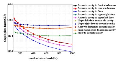
DLFs of the major subsystems were shown in Fig. 2 and CLFs for each junction calculated by analytical equations were shown in Fig. 3. As can be observed, the coupling loss factors of acoustic cavity to rear windscreen does not equal to the reverse one. This indicates the directionality of coupling loss factors.
Fig. 2DLFs for the principal structural subsystems
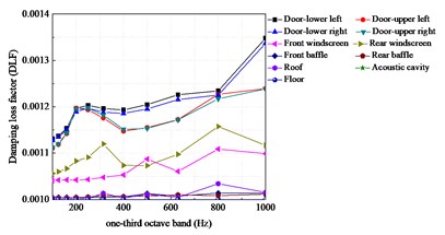
Fig. 3CLFs between the front windscreen and the acoustic cavity
3.3. Excitations of the hybrid cab model
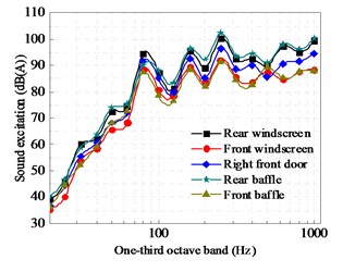
The cab mounting system is supported with four symmetric mounts: left front mount (L-F), right front mount (R-F), left rear mount (L-R) and right rear mount (R-R). Four accelerometers were placed in the passive sides of cab mounting system and accelerations of these were collected at the highest speed in static situation. Meanwhile, the sound radiation excitations were measured by surface acoustic sensors in same condition.
Then excitation forces can be figured out by imposing integral transform on acceleration signals. The forces were defined as follows:
where ¨x(f)active and ¨x(f)passive represent the acceleration at mounting system of the cab and the vehicle body, Ki represents the stiffness of the mount. The vibration and sound radiation excitations of the cab respectively was plotted in Fig. 4 and Fig. 5.
Fig. 4Vibration excitations for the mounting system
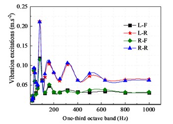
Fig. 5Sound excitations of the primary panels
3.4. Results analysis
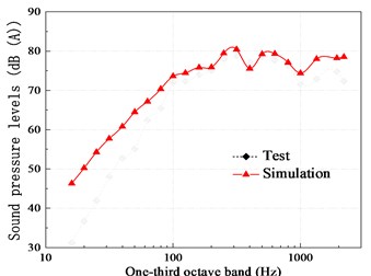
The results by averaging the sound responses through experiment in the engineering machinery cab is compared with that of the hybrid FE-SEA method plotted in Fig. 6. It is shown that in general the predicted results are in good agreement with the test results. The frequencies at the peaks and variation trend in the response are basically consistent from 100 Hz to 800 Hz. Some discrepancies were also observed at lower frequencies due to low modal density shown in Fig. 3 which does not meet the application assumptions of SEA in this band. Moreover, another possible reason could be the assumption of hard-wall boundary conditions, whereas the actual cab has tiny holes and gaps because of doors, windows and pipelines.
Fig. 6Comparisons (SPLs) between the predicted and test results
4. Conclusions
In this paper, studies of interior sound pressure response of the engineering machinery cab were made using the FE-SEA method. In the hybrid model the frame structure was described by finite element method while the panels such as windows, doors and windscreens were modeled based on the statistic energy method. Then parameters of the SEA, such as modal densities, DLFs and CLFs of substructures, were acquired by analytical methods. Finally, comparisons were used to validate the hybrid model and verify its accuracy through experimental results. It is shown that the hybrid FE-SEA method is an alternative for improve traditional deterministic or statistic models for structure-acoustic predictions in the mid-frequency range with a moderate computational cost and accuracy. It is worth noting that the hybrid method can only obtains the results averaging at frequencies and not get results at single frequencies. What’s more, it’s accuracy is closely to the application of frequency range.
References
-
Kumar Banerjee Prasanta, Butterfield Roy Boundary Element Methods in Engineering Science. Vol. 17, McGraw-Hill, London, 1981.
-
Brebbia Carlos A., Danson David J. The boundary element technique for the analysis of automotive structures. SAE Technical Paper 840733, 1984.
-
Heckl M. Structure-Borne-Sound. Noise Generation and Control in Mechanical Engineering. Springer Vienna, 1982.
-
Petyt Maurice Introduction to Finite Element Vibration Analysis. Cambridge University Press, 2010.
-
Woodhouse J. An introduction to statistical energy analysis of structural vibration. Applied Acoustics, Vol. 14, Issue 6, 1981, p. 455-469.
-
Lyon Richard H. Theory and Application of Statistical Energy Analysis. Elsevier, 2014.
-
Fahy Frank J. Statistical energy analysis: a critical overview. Philosophical Transactions of the Royal Society of London. Series A: Physical and Engineering Sciences, Vol. 346, Issue 1681, 1994, p. 431-447.
-
Courtney Burroughs B., Fischer Raymond W., Kern Fred R. An introduction to statistical energy analysis. The Journal of the Acoustical Society of America, Vol. 101, Issue 4, 1997, p. 1779-1789.
-
Shorter Phil Recent advances in automotive interior noise prediction. SAE Technical Paper 2008-36-0592, 2008.
-
Shorter Phil J., Langley R. S. Vibro-acoustic analysis of complex systems. Journal of Sound and Vibration, Vol. 288, Issue 3, 2005, p. 669-699.
-
Shorter Phil J., Langley Robin S. On the reciprocity relationship between direct field radiation and diffuse reverberant loading. Journal of the Acoustical Society of America, Vol. 117, Issue 1, 2005, p. 85-95.
-
Langley R. S., Shorter P. J., Contoni V. A hybrid FE-SEA method for the analysis of complex vibro-acoustic systems. Proceedings of the International Congress on Noise and Vibration Emerging Methods, 2005.
-
Langley R. S., et al. Hybrid deterministic-statistical modelling of built-up structures. 12th International Congress on Sound and Vibration, 2005.
-
Shorter Phil, Qijun Zhang, Parrett Alan Using the hybrid FE-SEA method to predict and diagnose component transmission loss. SAE Technical Paper, 2007-01-2172, 2007.
-
Prasanth S., Charpentier A., Fukui K. Using the hybrid FE-SEA model of a trimmed full vehicle to reduce structure borne noise from 200 Hz to 1 kHz. SAE Technical Paper 2011-26-0020, 2011.
-
Azevedo G. G., Bustamante M., Cordioli J. A., et al. Hybrid FE-SEA modeling and experimental validation of an aircraft floor structure for the analysis of vibration isolators. SAE Technical Paper 2012-36-0526, 2012.
-
Cordioli Julio, Vincent Cotoni, Phil Shorter Numerical investigation of the transmission loss of seals and slits for airborne SEA predictions. SAE Technical Paper 2009-01-2205, 2009.
About this article
This work is funded by Science and Technology Support Planning of Jiangsu Province (Grant No. BE201433), Science and Technology Achievement Transformation Project of Nanjing (No. 201701213) and Talent Introduction Fund Project of Hubei Polytechnic University (Grant Nos. 17xjz03R, 19xjk17R).
